Experimental and Numerical Analysis of Cylindrical Shell Buckling
VerifiedAdded on 2023/01/12
|31
|5517
|26
Report
AI Summary
This report details an experimental and numerical investigation into the buckling behavior of cylindrical shells. The study employs both experimental testing using a servo-hydraulic machine and numerical analysis utilizing Abaqus finite element software. The research focuses on the impact of sector angle length, boundary conditions, and other geometric parameters on the buckling load and post-buckling features of steel cylindrical panels. The numerical results are validated against the experimental data, demonstrating a close correlation between the two approaches. The report explores the application of cylindrical shells in various construction scenarios and the critical importance of understanding buckling phenomena under axial compression. The report also examines the influence of imperfections and different loading conditions, including meridional and circumferential compression, and shear stress. Finally, the report reviews the relevant Australian design standards for steel structures, comparing them with international standards and discussing the design considerations for fire resistance.
Cylindrical shells 1
EXPERIMENTAL STUDY AND NUMERICAL ANALYSIS OF STEEL CYLINDRICAL
PANEL BUCKLING FEATURES
By (Student’s Name)
Professor Name
University
City
Date
EXPERIMENTAL STUDY AND NUMERICAL ANALYSIS OF STEEL CYLINDRICAL
PANEL BUCKLING FEATURES
By (Student’s Name)
Professor Name
University
City
Date
Paraphrase This Document
Need a fresh take? Get an instant paraphrase of this document with our AI Paraphraser
Cylindrical shells 2
Abstract
The impact of the sector angle length and varying conditions of the boundary on post-buckling
and buckling load features of the cylindrical panel has been studied using the numerical and
experimental approach. Abaqus finite element tests have been conducted for numerical analysis
whereas the servo-hydraulic machine has been used in conducting the experimental tests. The
results for numerical analysis are similar to the experimental.
Keywords: Mechanical testing, buckling analysis, and plastic and elastic features
Cylindrical shells 3
Introduction
Cylindrical shells are commonly applied in a number of constructions. They are exposed to many
loading combinations. Axial compression is the most complex load that poses a threat on the thin
shell's stability. The failure modes that are so common in thin shell constructions are buckling
(Jawad, 2017). Over 60 years many studies have focused on the challenges of the axial
compression. The theory of linear shell was the first presented based on classic elasticity whereas
the second presentation was based on the approximation theory. The eighth order differential
equation was developed for determining the cylinder's critical strength with edges for support
under torsion. It was observed that the real edge support's first deviations and imperfections from
the theoretical state of the supports were the cause of the discrepancies between theoretical
buckling and experimental stress figures. A simple approach for analyzing the thin cylindrical
shell's elastic stability. The linear theory was also developed as a guide and created empirical
curves with the information of various earlier researchers. These tests showed a decrease in
critical stress compared to theoretical values. They observed that the buckle pattern revealed is
different from the theory based predictions. A huge deflection theory was employed to determine
the buckling feature of the long cylinders. It was revealed that long cylinders are able to be at
equilibrium in buckling conditions under minimal stress as compared to the linear theory's
critical stress. The buckle pattern present in the initial stages of buckling was also accounted for
successfully.
Many experiments were done on different long and short cylinders under axial compression.
Design curves were employed for the buckling coefficient against Batdorf parameter from 100 –
2000 and over 2000 for r/t ratios. The theoretical justification was presented for the influence of
the first geometrical discrepancies of the shell buckling load. NASA employed a monograph in
⊘ This is a preview!⊘
Do you want full access?
Subscribe today to unlock all pages.
Trusted by 1+ million students worldwide
Cylindrical shells 4
which the analysis and design criteria are covered for both unstiffened and stiffened circular thin
walled shells under many loading states. Experimentation based design charts and empirical
formulae were provided too. Charts and practical design equations were developed to
approximate the buckling strength of both the imperfect and perfect tanks and cylindrical shells
under loads axially compressed based on parametric research using ABAQUS. The nonlinear in
thin-wall members were studied and the impacts of the first imperfections as a result of the
residual and geometry stress. Tests conducted on the imperfect shells exposed to transverse load
and the nonlinear FE model imperfection was modelled using ABAQUS. Two models were
created whereby in the first, the actual imperfections were imposed at every node. In the second
FE model, the imposition of the imperfections was by renormalization of the eigenmode where
the maximum imperfection measured was applied. Circular- compressed shell cylinders with
geometric imperfections were analyzed for the dynamic and static environment. The Sanders
shell theory and Donnel’s theory of nonlinear shallow-shell were applied for the analysis.
Shell structures are commonly used in marine structures, shell roofs, pipelines, cooling towers,
aerospace and liquid-retaining structures. One of the major challenges in designing such
structures is buckling. Researchers initially focused on determining the buckling load exposed to
linear elastic zone however these were experimental research. It was revealed that the buckling
capacity of thin cylindrical shells is very low as compared to that quantity found in the classical
theory. Thin cylindrical panels can be used in many structures. Where the stress distribution in
these structures is compressive, such structures may collapse in most cases before the buckling
phenomena reveal its capacity of loading or yielding because of the huge radius values to the
thickness ration. The subject was conducted using the numerical approach based on the
analytical method and finite element (FE) inside the elastic area. The actual solution for
Paraphrase This Document
Need a fresh take? Get an instant paraphrase of this document with our AI Paraphraser
Cylindrical shells 5
anisotropic and isotropic panels was determined. The simply supported panel's stability exposed
to distributed external pressure was studied. The Donnel’s equation for Buckling of three-edged
panels simply supported was solved and one-edged free under an axial load using the Galerkin
approach (Hui-shen, 2017). Experimental and numerical tests on cylindrical panels axially
loaded for postbuckling were conducted with simply supported edges and curved clamped edges.
The Australian standards in regards to designing steel structures are different from other
international standards as it does not involve a particular publication concerning the design of
structural fire. Instead, policies for designing structures related to fire are found in every steel-
related principal standards of designs. They include:
AS/NZS 5100.6 Bridge Design – composite and steel construction
AS 4100 steel structures
AS/NZS 4600 - structures with cold-formed steel
AS/NZS 2327composite structures – buildings constructed with composite steel-concrete
Different standards can be at varying stages of performance-based implementation methods for
engineering fire designs.
Experimental studies of cold-formed tube columns of stainless steel filled with concrete and high
strengths exposed to distributed axial compression were presented. The impact of plate thickness,
tube shapes and strength of concrete were also studied. The results of the test were compared to
the Australian and American standards. The strength and failure modes of aluminium alloy with
and with no transverse weld axially compressed between fixed edges. Among the failure modes
Cylindrical shells 6
observed include buckling and yielding for various lengths. The results of the test were
compared to other aluminium standards for structures (Matsagar, 2014).
An experimental approach for hollow cold-formed squared stainless steel sections exposed to
axially pure compression was described. The conclusion was that the Australian design policies
are very reliable as compared to the European and American specifications for studies
conducted. Numerical and experimental studies on the efficiency of thin-skinned repaired
composite panels with stiffened blades inside the post-buckling range have been performed. The
results revealed that the panel's strength can be satisfactorily restored under the present repair
plan. Additionally, the repair plan was observed to have the ability to recover the load's general
path in panels and the general post-buckling feature.
This article focuses on the experimental and numerical research conducted on cylindrical panels
to determine the bulking load and evaluate the post-bulking features of the panels. The Abaqus
(FE) element has been applied for the numerical analysis to determine the impact of the sector
angle, thickness, length and different boundary states (Zamani, 2017). For the experimental
study, tests on the panels were conducted using the servo-hydraulic machine. The experimental
results are similar to the numerical ones. Based on this study, the panel's buckling load can be
approximated which relies on the mechanical and geometrical features of it. The experimented
panels that have been clamped and constrained between simple supports contain two boundary
states. Thus the average buckling coefficient of the two boundaries can be applied to get a
correlation.
⊘ This is a preview!⊘
Do you want full access?
Subscribe today to unlock all pages.
Trusted by 1+ million students worldwide
Cylindrical shells 7
Analysis: Circular Cylindrical Panel Buckling from Axial Compression
Finite Element Method
This is the computational approach applied to get the estimate solutions of limit value
challenges. These boundary value challenges are also known as field difficulties. The areas of
focus are the field challenges which usually represent the actual structures. The field difficulties
are outlined using the differential equation discretization contained in the element method. These
elements provide approximated strains and stresses experienced by complete structures. Based
on the structure's complexity, type of every element and the number of finite elements, the FEM
estimate solutions will be varied. Nodes are zones at which the mesh elements are linked. The
mesh is the structure in which all elements are connected whereby the mesh is either crude or
fine based on the size of a finite element. Developing a very fine field grading mesh can cause
unwanted computational power hence resulting in convergence analysis. The commercial
Abaqus software is the most suitable in developing a 3D model which forms an FE model with
3D modelling (Rao, 2017).
Abaqus model
This part describes the Abaqus model and the method of placing up the model. There are the
required procedural steps for running the model as well as setting up it up.
Shell Element
The initial modelling procedure of the shell’s structure is by defining the areas which form the
complete structure whereby only a single element is needed. This element is formed as a shell
element that can be perceived as an amalgamation of disc and plate elements. Disc features are
used to evaluate structures predisposed to in-plane forces with two translation of in-plane
Paraphrase This Document
Need a fresh take? Get an instant paraphrase of this document with our AI Paraphraser
Cylindrical shells 8
degrees of freedom. The plate features contain a single out of a plane’s degree of freedom and
two out of the rotational plane degrees of freedom (Rao, 2017). An additional sixth degree of
freedom with a degree of freedom rotational features known as the drilling degree of freedom is
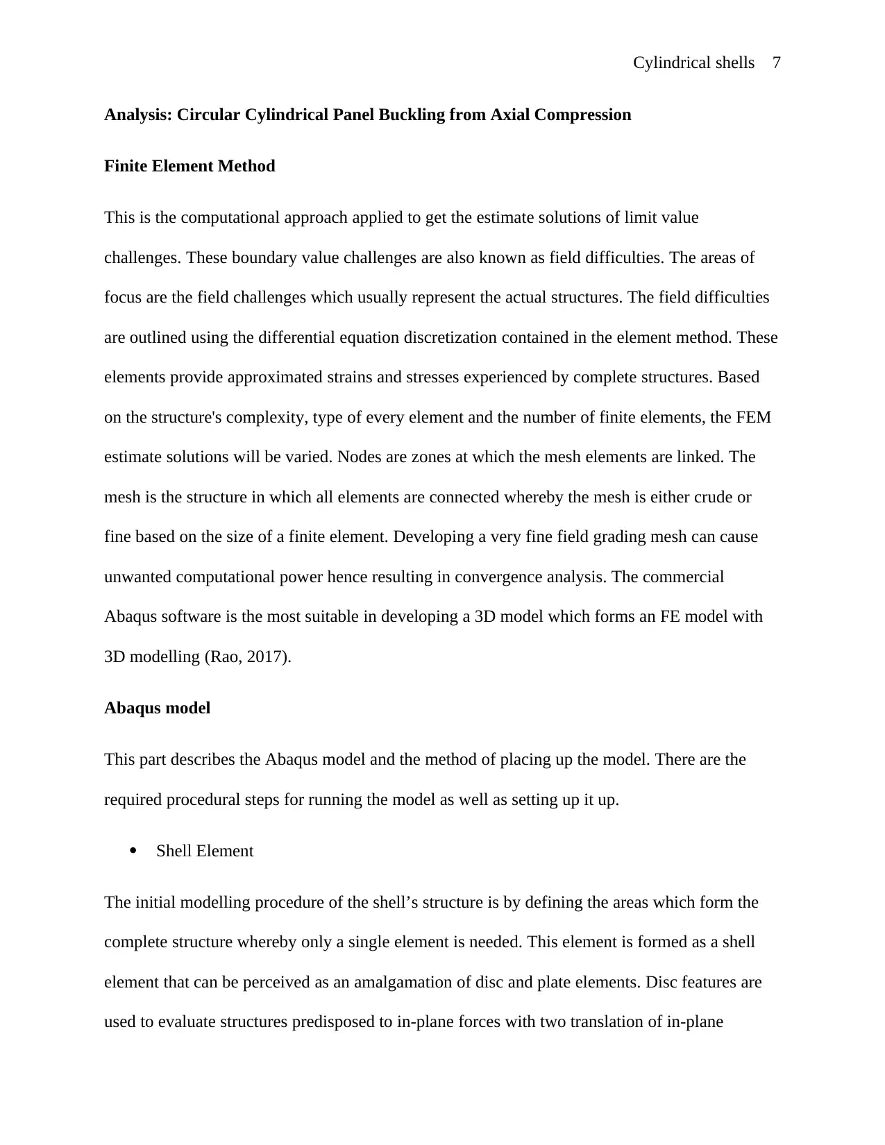
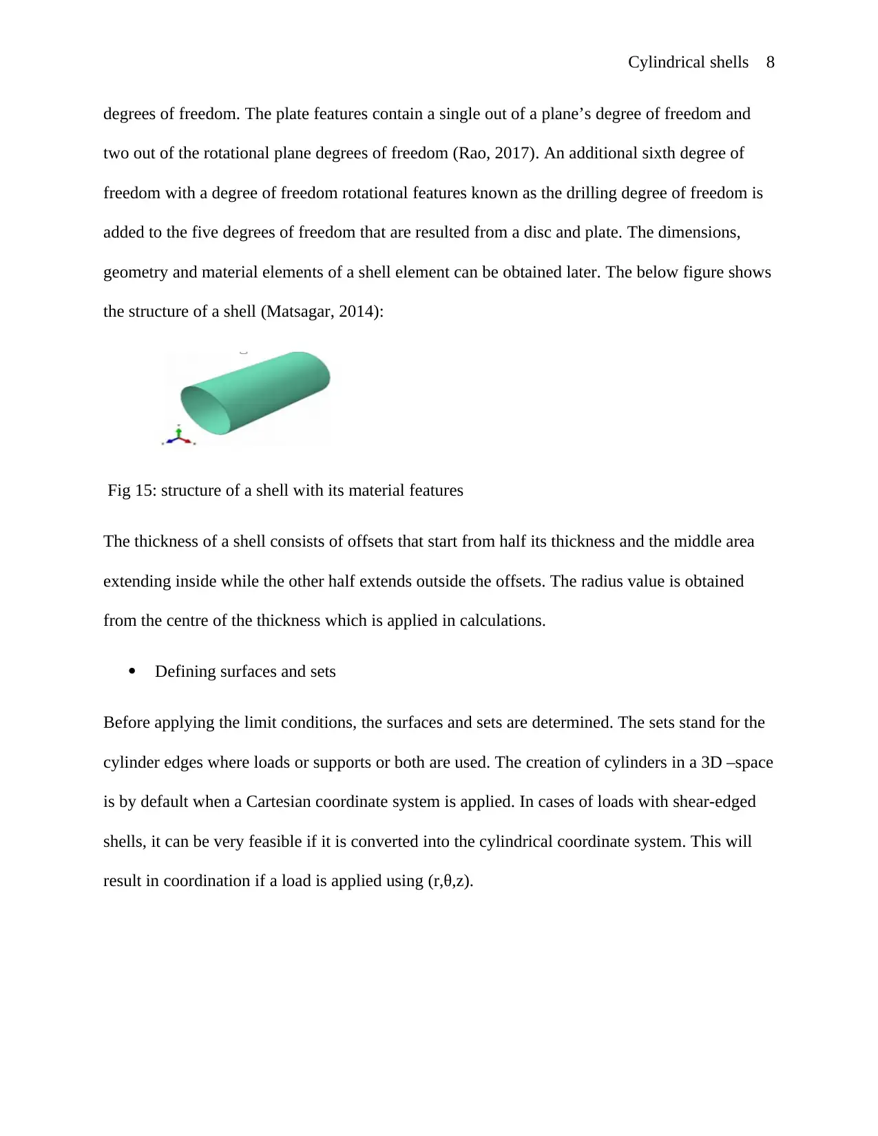
added to the five degrees of freedom that are resulted from a disc and plate. The dimensions,
geometry and material elements of a shell element can be obtained later. The below figure shows
the structure of a shell (Matsagar, 2014):
Fig 15: structure of a shell with its material features
The thickness of a shell consists of offsets that start from half its thickness and the middle area
extending inside while the other half extends outside the offsets. The radius value is obtained
from the centre of the thickness which is applied in calculations.
Defining surfaces and sets
Before applying the limit conditions, the surfaces and sets are determined. The sets stand for the
cylinder edges where loads or supports or both are used. The creation of cylinders in a 3D –space
is by default when a Cartesian coordinate system is applied. In cases of loads with shear-edged
shells, it can be very feasible if it is converted into the cylindrical coordinate system. This will
result in coordination if a load is applied using (r,θ,z).
degrees of freedom. The plate features contain a single out of a plane’s degree of freedom and
two out of the rotational plane degrees of freedom (Rao, 2017). An additional sixth degree of
freedom with a degree of freedom rotational features known as the drilling degree of freedom is
added to the five degrees of freedom that are resulted from a disc and plate. The dimensions,
geometry and material elements of a shell element can be obtained later. The below figure shows
the structure of a shell (Matsagar, 2014):
Fig 15: structure of a shell with its material features
The thickness of a shell consists of offsets that start from half its thickness and the middle area
extending inside while the other half extends outside the offsets. The radius value is obtained
from the centre of the thickness which is applied in calculations.
Defining surfaces and sets
Before applying the limit conditions, the surfaces and sets are determined. The sets stand for the
cylinder edges where loads or supports or both are used. The creation of cylinders in a 3D –space
is by default when a Cartesian coordinate system is applied. In cases of loads with shear-edged
shells, it can be very feasible if it is converted into the cylindrical coordinate system. This will
result in coordination if a load is applied using (r,θ,z).
Cylindrical shells 9
Boundary states
The model’s limit conditions include the supports that define loads and restrictions used on
structures.
Supports
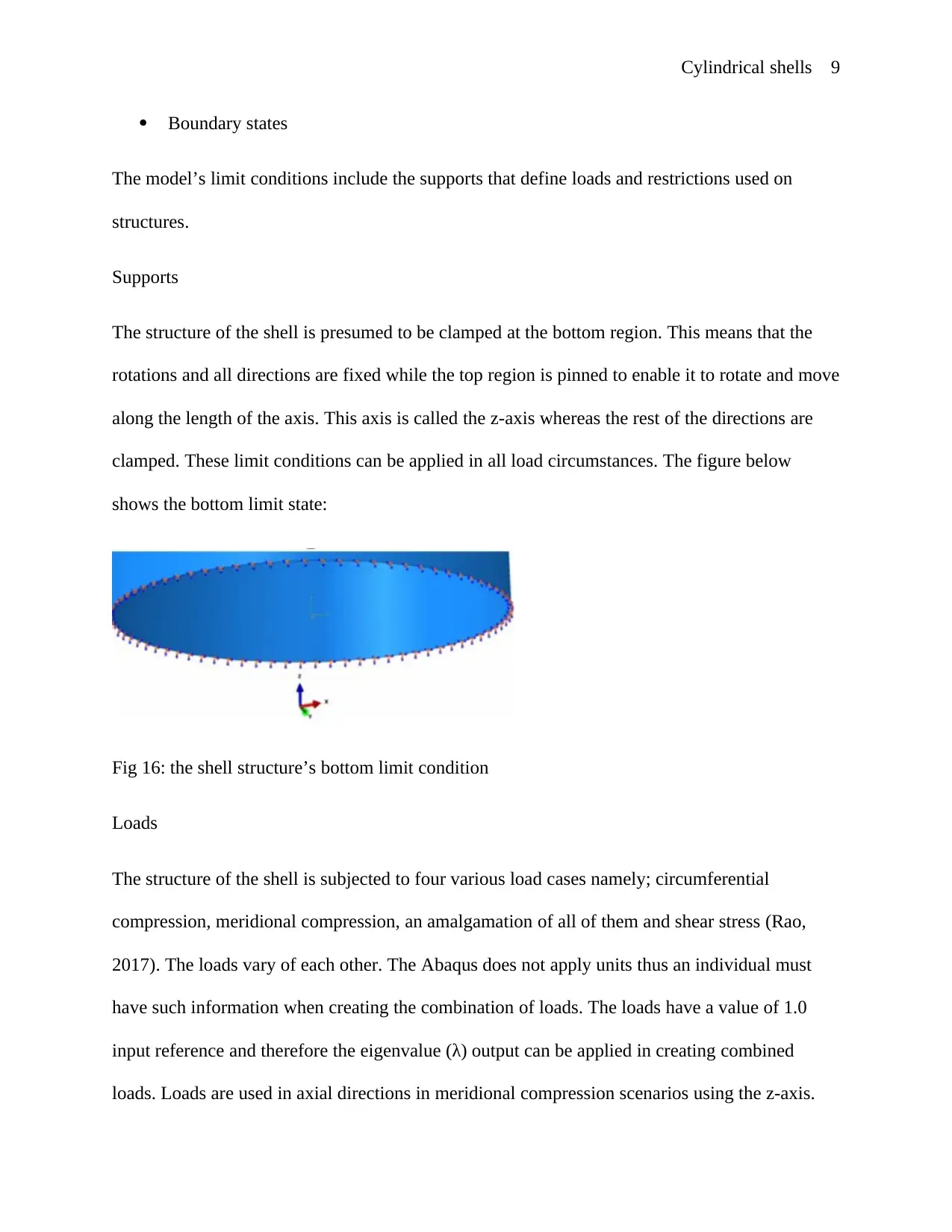
The structure of the shell is presumed to be clamped at the bottom region. This means that the
rotations and all directions are fixed while the top region is pinned to enable it to rotate and move
along the length of the axis. This axis is called the z-axis whereas the rest of the directions are
clamped. These limit conditions can be applied in all load circumstances. The figure below
shows the bottom limit state:
Fig 16: the shell structure’s bottom limit condition
Loads
The structure of the shell is subjected to four various load cases namely; circumferential
compression, meridional compression, an amalgamation of all of them and shear stress (Rao,
2017). The loads vary of each other. The Abaqus does not apply units thus an individual must
have such information when creating the combination of loads. The loads have a value of 1.0
input reference and therefore the eigenvalue (λ) output can be applied in creating combined
loads. Loads are used in axial directions in meridional compression scenarios using the z-axis.
Boundary states
The model’s limit conditions include the supports that define loads and restrictions used on
structures.
Supports
The structure of the shell is presumed to be clamped at the bottom region. This means that the
rotations and all directions are fixed while the top region is pinned to enable it to rotate and move
along the length of the axis. This axis is called the z-axis whereas the rest of the directions are
clamped. These limit conditions can be applied in all load circumstances. The figure below
shows the bottom limit state:
Fig 16: the shell structure’s bottom limit condition
Loads
The structure of the shell is subjected to four various load cases namely; circumferential
compression, meridional compression, an amalgamation of all of them and shear stress (Rao,
2017). The loads vary of each other. The Abaqus does not apply units thus an individual must
have such information when creating the combination of loads. The loads have a value of 1.0
input reference and therefore the eigenvalue (λ) output can be applied in creating combined
loads. Loads are used in axial directions in meridional compression scenarios using the z-axis.
⊘ This is a preview!⊘
Do you want full access?
Subscribe today to unlock all pages.
Trusted by 1+ million students worldwide
Cylindrical shells 10
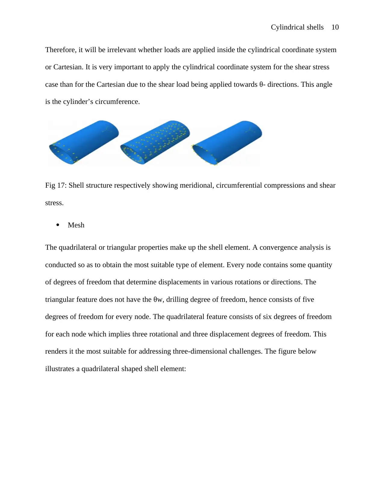
Therefore, it will be irrelevant whether loads are applied inside the cylindrical coordinate system
or Cartesian. It is very important to apply the cylindrical coordinate system for the shear stress
case than for the Cartesian due to the shear load being applied towards θ- directions. This angle
is the cylinder’s circumference.
Fig 17: Shell structure respectively showing meridional, circumferential compressions and shear
stress.
Mesh
The quadrilateral or triangular properties make up the shell element. A convergence analysis is
conducted so as to obtain the most suitable type of element. Every node contains some quantity
of degrees of freedom that determine displacements in various rotations or directions. The
triangular feature does not have the θw, drilling degree of freedom, hence consists of five
degrees of freedom for every node. The quadrilateral feature consists of six degrees of freedom
for each node which implies three rotational and three displacement degrees of freedom. This
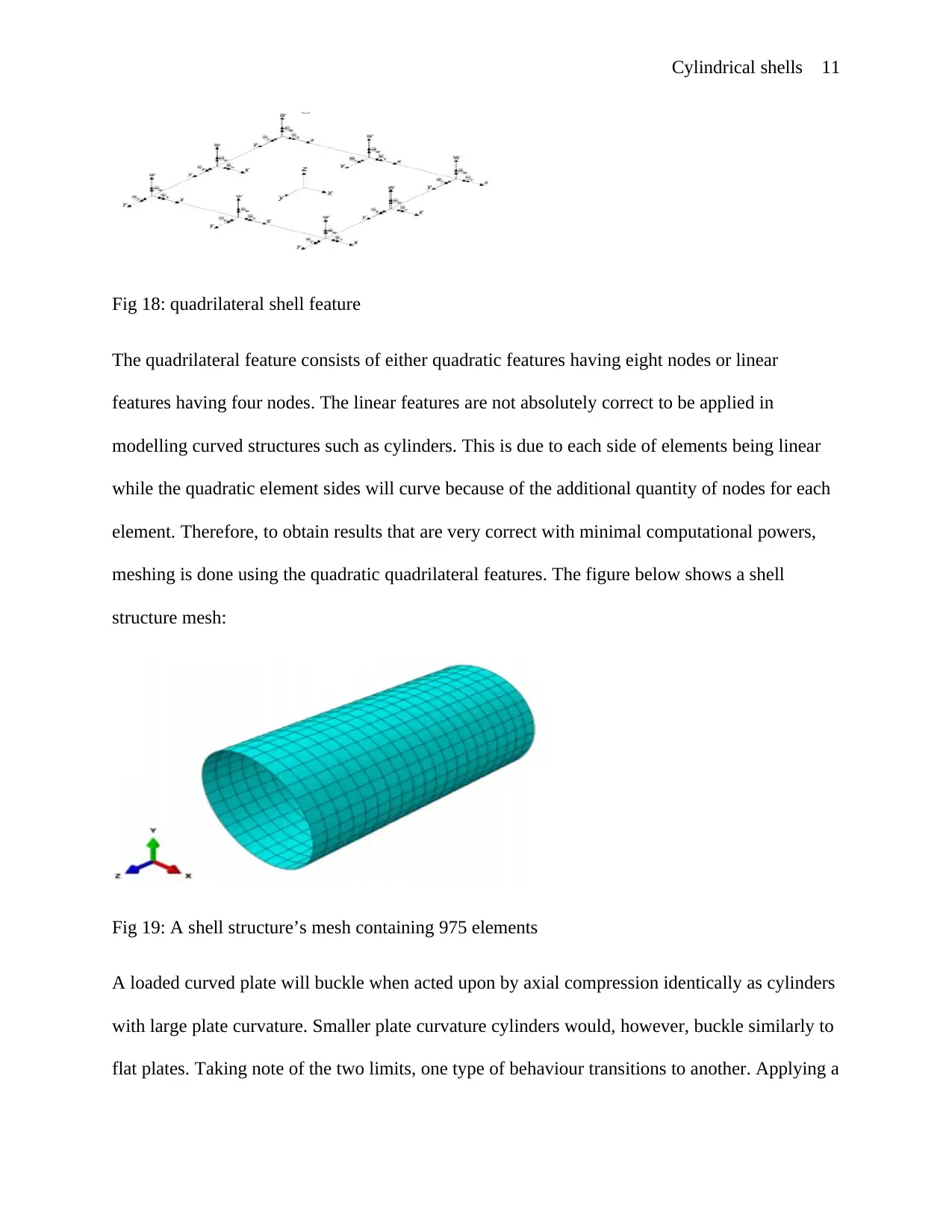
renders it the most suitable for addressing three-dimensional challenges. The figure below
illustrates a quadrilateral shaped shell element:
Therefore, it will be irrelevant whether loads are applied inside the cylindrical coordinate system
or Cartesian. It is very important to apply the cylindrical coordinate system for the shear stress
case than for the Cartesian due to the shear load being applied towards θ- directions. This angle
is the cylinder’s circumference.
Fig 17: Shell structure respectively showing meridional, circumferential compressions and shear
stress.
Mesh
The quadrilateral or triangular properties make up the shell element. A convergence analysis is
conducted so as to obtain the most suitable type of element. Every node contains some quantity
of degrees of freedom that determine displacements in various rotations or directions. The
triangular feature does not have the θw, drilling degree of freedom, hence consists of five
degrees of freedom for every node. The quadrilateral feature consists of six degrees of freedom
for each node which implies three rotational and three displacement degrees of freedom. This
renders it the most suitable for addressing three-dimensional challenges. The figure below
illustrates a quadrilateral shaped shell element:
Paraphrase This Document
Need a fresh take? Get an instant paraphrase of this document with our AI Paraphraser
Cylindrical shells 11
Fig 18: quadrilateral shell feature
The quadrilateral feature consists of either quadratic features having eight nodes or linear
features having four nodes. The linear features are not absolutely correct to be applied in
modelling curved structures such as cylinders. This is due to each side of elements being linear
while the quadratic element sides will curve because of the additional quantity of nodes for each
element. Therefore, to obtain results that are very correct with minimal computational powers,
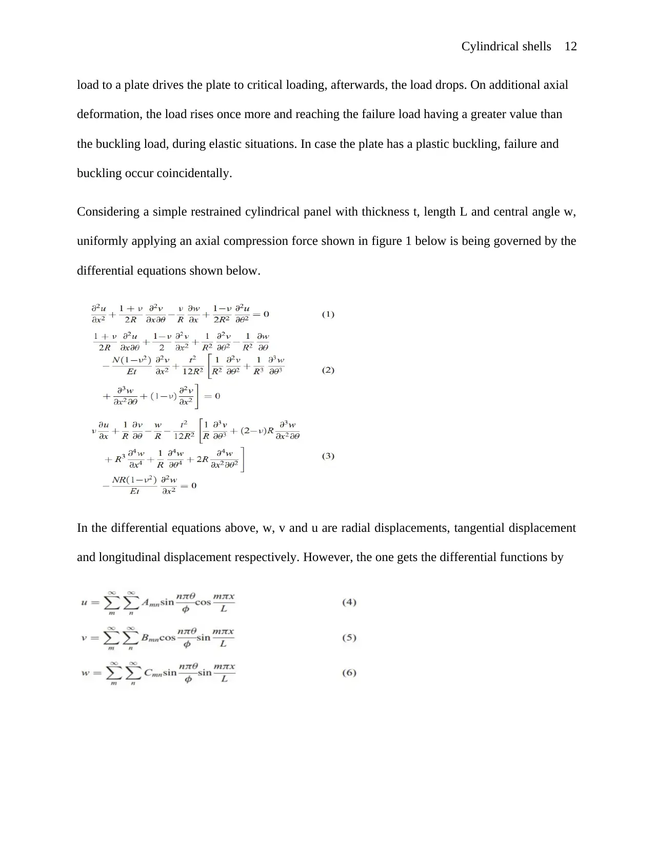
meshing is done using the quadratic quadrilateral features. The figure below shows a shell
structure mesh:
Fig 19: A shell structure’s mesh containing 975 elements
A loaded curved plate will buckle when acted upon by axial compression identically as cylinders
with large plate curvature. Smaller plate curvature cylinders would, however, buckle similarly to
flat plates. Taking note of the two limits, one type of behaviour transitions to another. Applying a
Fig 18: quadrilateral shell feature
The quadrilateral feature consists of either quadratic features having eight nodes or linear
features having four nodes. The linear features are not absolutely correct to be applied in
modelling curved structures such as cylinders. This is due to each side of elements being linear
while the quadratic element sides will curve because of the additional quantity of nodes for each
element. Therefore, to obtain results that are very correct with minimal computational powers,
meshing is done using the quadratic quadrilateral features. The figure below shows a shell
structure mesh:
Fig 19: A shell structure’s mesh containing 975 elements
A loaded curved plate will buckle when acted upon by axial compression identically as cylinders
with large plate curvature. Smaller plate curvature cylinders would, however, buckle similarly to
flat plates. Taking note of the two limits, one type of behaviour transitions to another. Applying a
Cylindrical shells 12
load to a plate drives the plate to critical loading, afterwards, the load drops. On additional axial
deformation, the load rises once more and reaching the failure load having a greater value than
the buckling load, during elastic situations. In case the plate has a plastic buckling, failure and
buckling occur coincidentally.
Considering a simple restrained cylindrical panel with thickness t, length L and central angle w,
uniformly applying an axial compression force shown in figure 1 below is being governed by the
differential equations shown below.
In the differential equations above, w, v and u are radial displacements, tangential displacement
and longitudinal displacement respectively. However, the one gets the differential functions by
⊘ This is a preview!⊘
Do you want full access?
Subscribe today to unlock all pages.
Trusted by 1+ million students worldwide
1 out of 31
Your All-in-One AI-Powered Toolkit for Academic Success.
+13062052269
info@desklib.com
Available 24*7 on WhatsApp / Email
![[object Object]](/_next/static/media/star-bottom.7253800d.svg)
Unlock your academic potential
Copyright © 2020–2026 A2Z Services. All Rights Reserved. Developed and managed by ZUCOL.