Detailed Solution: DAC, Filter & Transistor Circuit Analysis Task

Verified

Added on  2023/06/08

|6
|837
|151
Homework Assignment
AI Summary
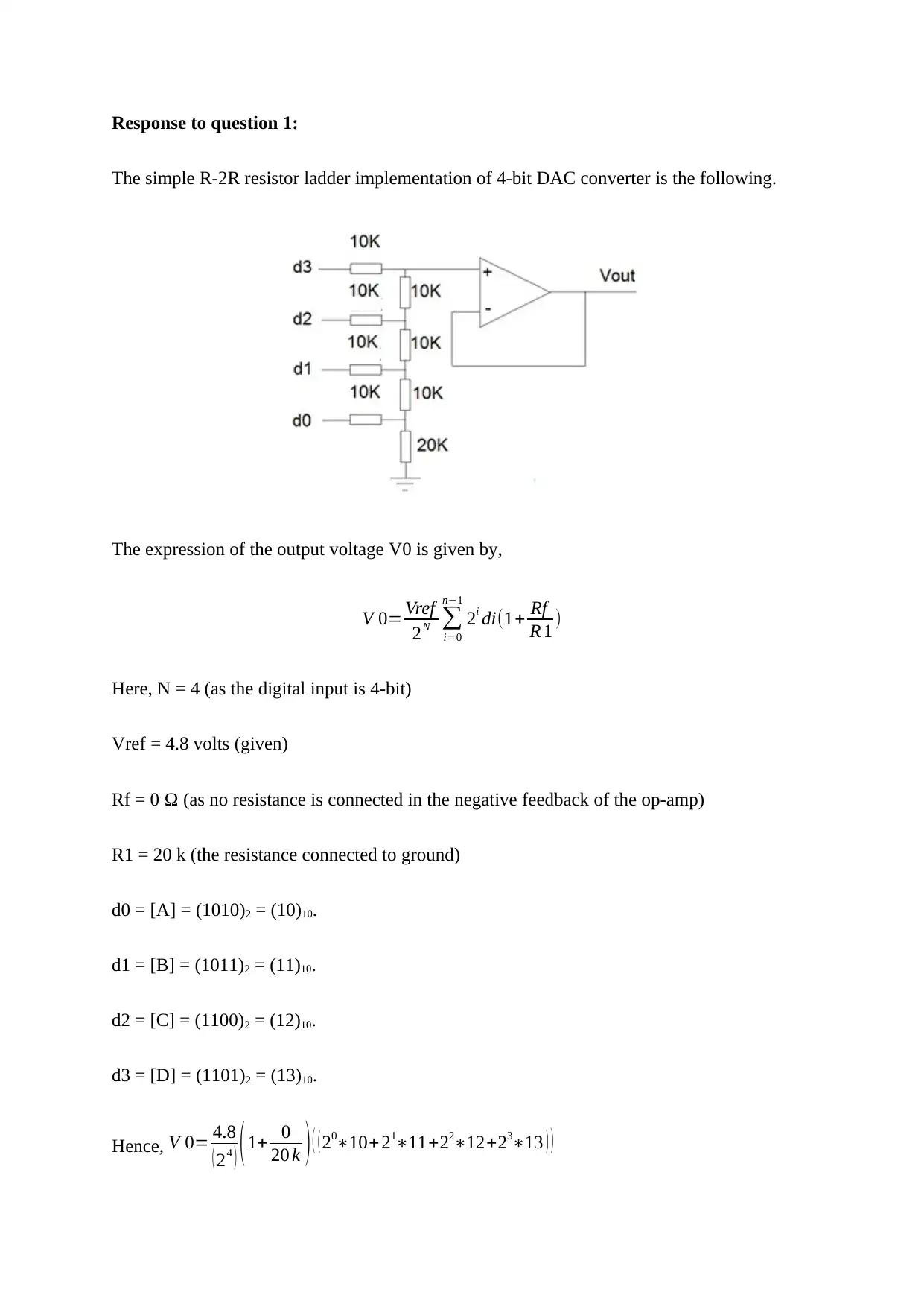
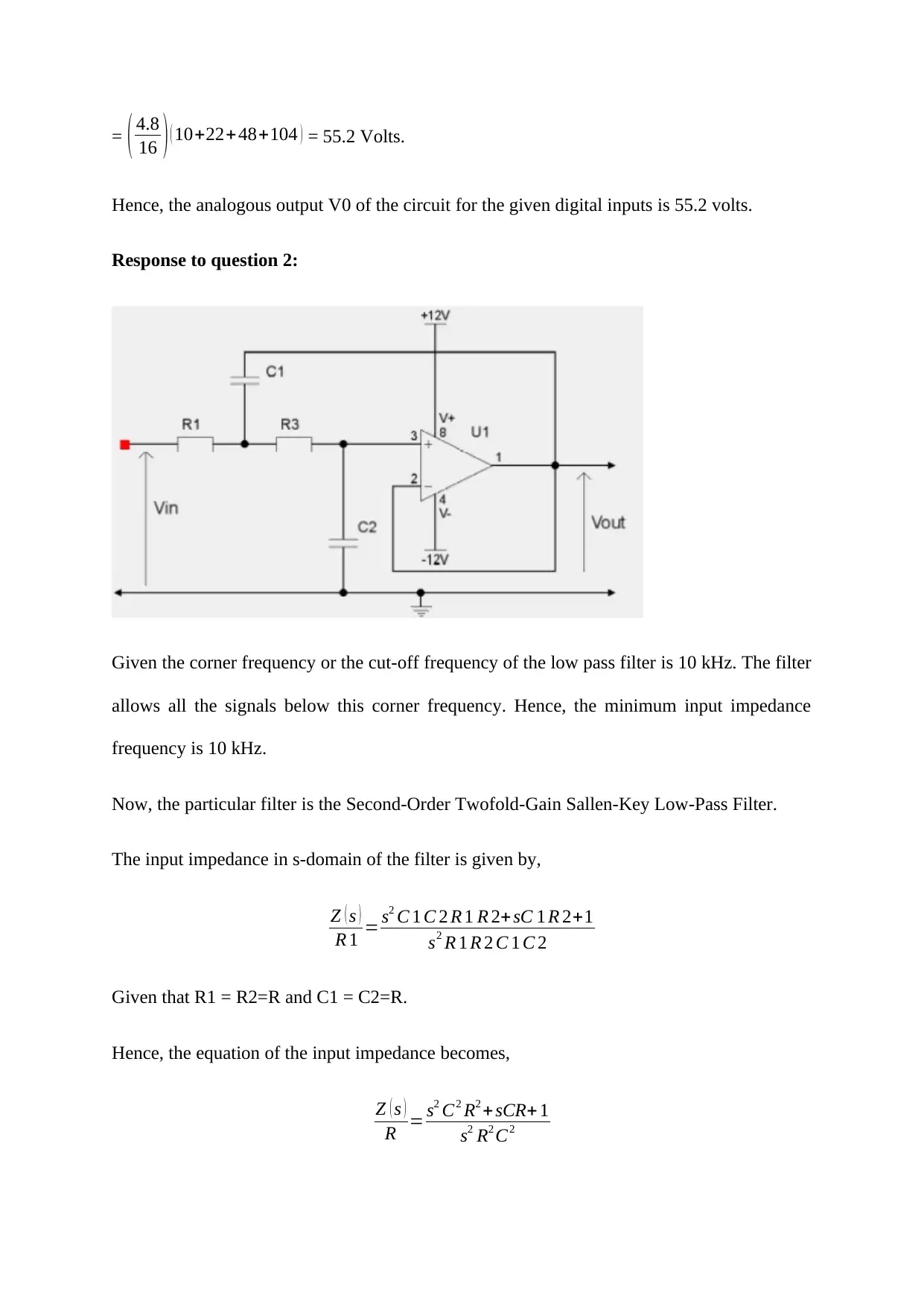
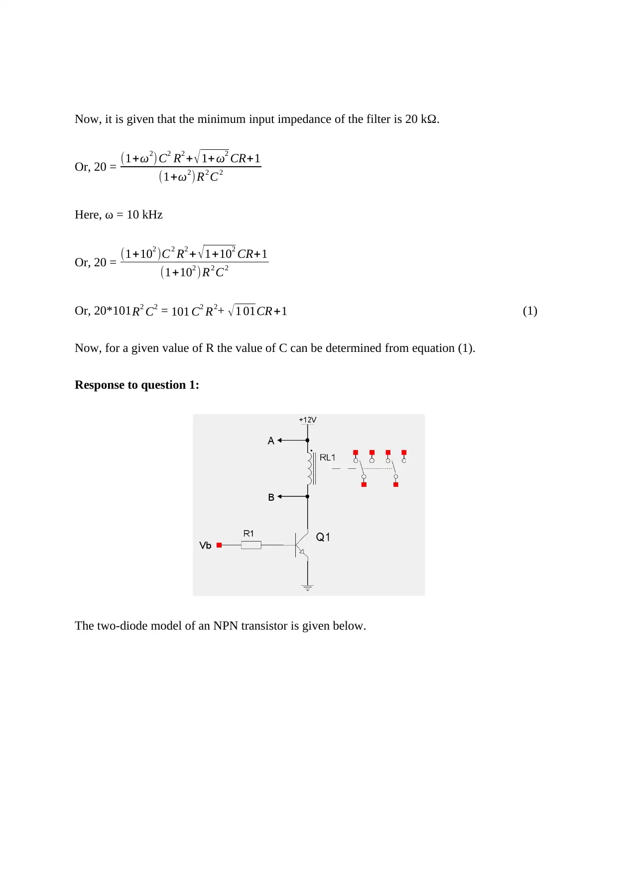
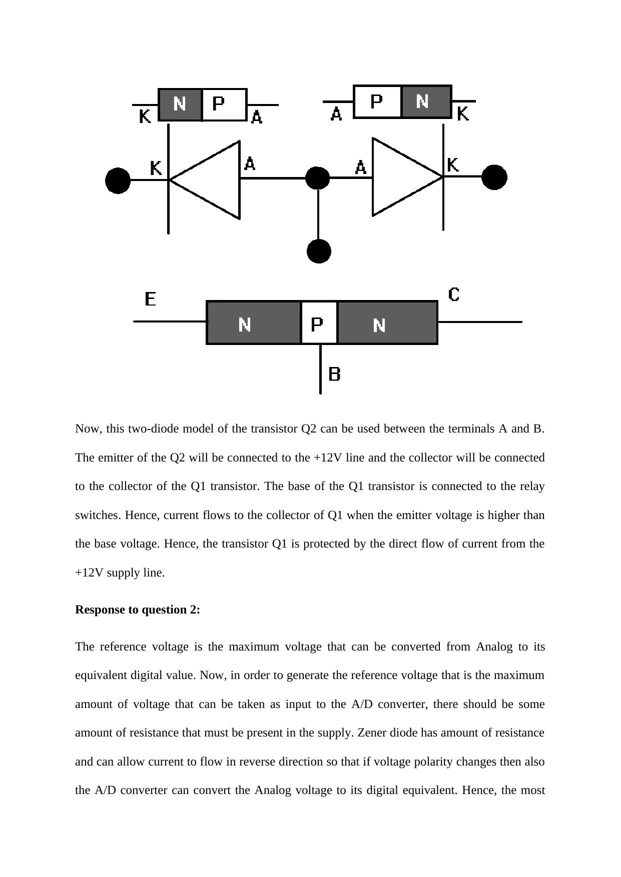
This assignment provides solutions to problems related to electrical engineering circuits. It begins with the analysis of a 4-bit DAC converter using an R-2R resistor ladder, calculating the output voltage for given digital inputs. Next, it addresses the design of a low-pass filter, specifically a Second-Order Twofold-Gain Sallen-Key Low-Pass Filter, determining the required capacitance value based on the corner frequency and minimum input impedance. Lastly, it discusses a relay drive circuit, proposing the use of a spare NPN transistor for transistor protection and explaining the selection of a Zener diode for generating a reference voltage for an Analog to Digital converter, along with calculating the required resistance value to ensure proper circuit operation across a production run. Desklib provides a range of solved assignments and past papers for students.
Document Page
Response to question 1:
The simple R-2R resistor ladder implementation of 4-bit DAC converter is the following.
The expression of the output voltage V0 is given by,
V 0= Vref
2N
i=0
n1
2i di(1+ Rf
R 1 )
Here, N = 4 (as the digital input is 4-bit)
Vref = 4.8 volts (given)
Rf = 0 Ω (as no resistance is connected in the negative feedback of the op-amp)
R1 = 20 k (the resistance connected to ground)
d0 = [A] = (1010)2 = (10)10.
d1 = [B] = (1011)2 = (11)10.
d2 = [C] = (1100)2 = (12)10.
d3 = [D] = (1101)2 = (13)10.
Hence, V 0= 4.8
( 24 ) (1+ 0
20 k ) ( ( 2010+ 2111+2212+2313 ) )
tabler-icon-diamond-filled.svg

Paraphrase This Document

Need a fresh take? Get an instant paraphrase of this document with our AI Paraphraser
Document Page
= ( 4.8
16 ) ( 10+22+ 48+104 ) = 55.2 Volts.
Hence, the analogous output V0 of the circuit for the given digital inputs is 55.2 volts.
Response to question 2:
Given the corner frequency or the cut-off frequency of the low pass filter is 10 kHz. The filter
allows all the signals below this corner frequency. Hence, the minimum input impedance
frequency is 10 kHz.
Now, the particular filter is the Second-Order Twofold-Gain Sallen-Key Low-Pass Filter.
The input impedance in s-domain of the filter is given by,
Z ( s )
R 1 = s2 C 1 C 2 R 1 R 2+ sC 1 R 2+1
s2 R 1 R 2 C 1 C 2
Given that R1 = R2=R and C1 = C2=R.
Hence, the equation of the input impedance becomes,
Z ( s )
R = s2 C2 R2 + sCR+ 1
s2 R2 C2
Document Page
Now, it is given that the minimum input impedance of the filter is 20 kΩ.
Or, 20 = (1+ω2) C2 R2 + 1+ω2 CR+1
(1+ω2)R2 C2
Here, ω = 10 kHz
Or, 20 = (1+102 )C2 R2 + 1+102 CR+1
(1+102 )R2 C2
Or, 20*101R2 C2 = 101 C2 R2+ 1 01CR+1 (1)
Now, for a given value of R the value of C can be determined from equation (1).
Response to question 1:
The two-diode model of an NPN transistor is given below.
Document Page
Now, this two-diode model of the transistor Q2 can be used between the terminals A and B.
The emitter of the Q2 will be connected to the +12V line and the collector will be connected
to the collector of the Q1 transistor. The base of the Q1 transistor is connected to the relay
switches. Hence, current flows to the collector of Q1 when the emitter voltage is higher than
the base voltage. Hence, the transistor Q1 is protected by the direct flow of current from the
+12V supply line.
Response to question 2:
The reference voltage is the maximum voltage that can be converted from Analog to its
equivalent digital value. Now, in order to generate the reference voltage that is the maximum
amount of voltage that can be taken as input to the A/D converter, there should be some
amount of resistance that must be present in the supply. Zener diode has amount of resistance
and can allow current to flow in reverse direction so that if voltage polarity changes then also
the A/D converter can convert the Analog voltage to its digital equivalent. Hence, the most
tabler-icon-diamond-filled.svg

Paraphrase This Document

Need a fresh take? Get an instant paraphrase of this document with our AI Paraphraser
Document Page
satisfactory way of generating a reference voltage for an Analog to digital converter is a)
using a Zener diode.
Response to question 3:
Given that the supply voltage Vcc = 12 V.
The base-emitter voltage when the transistor Q1 is saturated is 0.7 volts.
Now, given that the minimum value of current required for working the circuit in production
run i.e. the minimum current required that the relay coil stay pulled in is 1.75 Amps.
Hence, the minimum current that should flow across R1 is 1.75 A.
Now, Voltage(D0) = 12 volts.
Voltage(base of Q1) = 0.7 volts.
Hence, (12-0.7)/R1 = 1.75 Amps.
R1 = (12-0.7)/1.75 = 6.457 Ω ~ 6 Ω.
Document Page
Hence, the minimum value of R1 required to ensure the circuit will work across a production
run is 6 Ω.
chevron_up_icon
1 out of 6
circle_padding
hide_on_mobile
zoom_out_icon
[object Object]