Data Analysis and Design Report: Relational Database for FTHC
VerifiedAdded on 2019/12/03
|23
|5165
|232
Report
AI Summary
This report provides a detailed analysis of data analysis and database design principles, focusing on the case of Fast Track Health Centre (FTHC). It begins with a critical comparison of different data models (hierarchical, network, and relational), discussing their data structures, manipulation, and integrity aspects. The report then explores the benefits and limitations of database technologies compared to traditional file systems, highlighting the importance of reducing data redundancy. Different approaches to database design, including top-down and bottom-up methods, are examined, along with the use of data flow diagrams and entity relationship diagrams. The core of the report involves designing a relational database system to meet FTHC's requirements, including conceptual, logical, and physical database designs, normalization, and the use of tools and techniques. The report also covers the building of a relational database system, implementation of query languages, and a critical evaluation of query tools. Finally, the report reviews and tests the relational database system, providing documentation, user guides, verification, validation, and control mechanisms, to improve the present system.

Data analysis and design
Paraphrase This Document
Need a fresh take? Get an instant paraphrase of this document with our AI Paraphraser
Table of Contents
INTRODUCTION...........................................................................................................................1
TASK 1............................................................................................................................................1
1.1 Critical comparison between different data models and schemas.........................................1
1.2 Critical discussion of benefits and limitations of different database technologies................3
1.3 Analyze different approaches to database design..................................................................4
1.4 Explain top-down and bottom-up approaches.......................................................................6
TASK 2............................................................................................................................................7
2.1 Design a relational database system to meet a given requirement........................................7
2.2 Building a relational database system based on a prepared design.......................................4
2.3 A range of database tools and techniques to enhance the user interface...............................4
2.4 Crow’s foot notation..............................................................................................................4
2.5 Critical reflection...................................................................................................................6
TASK 3............................................................................................................................................6
3.1 Benefits of using manipulation and query tools....................................................................6
3.2 Implementation of a query language into the relational database system.............................7
3.3 Critically evaluation of query tools used in data extraction..................................................8
3.4 Advantages of query in database...........................................................................................8
TASK 4............................................................................................................................................8
4.1 Review and test a relational database system........................................................................8
4.2 Documentation to support the implementation and testing of a relational database.............9
4.3 User documentation for a developed relational database system..........................................9
4.4 Explain the ways through which verification and validation has been addressed.................9
4.5 Control mechanisms..............................................................................................................9
4.6 Testing and implementation of database system.................................................................10
4.7 Appropriate decisions to improve present system...............................................................10
CONCLUSION..............................................................................................................................11
REFERENCES..............................................................................................................................12
3
⊘ This is a preview!⊘
Do you want full access?
Subscribe today to unlock all pages.
Trusted by 1+ million students worldwide
List of figures
Figure 1: File management system (data redundancy)....................................................................7
Figure 2: Database management (data redundancy)........................................................................7
Figure 3: Data flow diagram............................................................................................................8
Figure 4: Entity relationship diagram..............................................................................................9
Figure 5: Top-down approach.........................................................................................................9
Figure 6: Bottom-up approach.......................................................................................................10
Figure 7: 0-Level DFD..................................................................................................................13
Figure 8: 1-Level diagram.............................................................................................................13
Figure 9: Patient enquiry form.......................................................................................................14
Figure 10: Testing and implementation of database......................................................................20
List of tables
Table 1: Database schema..............................................................................................................6
Table 2: Conceptual data model....................................................................................................10
Table 3: Logical database design...................................................................................................11
Table 4: Crow’s Foot notation.......................................................................................................15
Table 5: Speciliast_details table....................................................................................................17
Table 6: Room_details...................................................................................................................17
Table 7: Patient_details table.........................................................................................................17
Table 8: Recpt and FTHC_details table.........................................................................................17
Table 9: Verification and Validation table....................................................................................19
Paraphrase This Document
Need a fresh take? Get an instant paraphrase of this document with our AI Paraphraser
INTRODUCTION
Data analysis and design is an important problem solving technique and it allows
database users to maintain records or details without any redundancy. As per the present case
scenario, Fast Track Health Centre (FTHC) has been taken into consideration which provides
quality of services to its patients and operated by health care professionals. Furthermore, report
provides details about different data models and approaches of database design with the help of
discussing some real world’s problems in a significant manner. In addition, relationship database
design and database system on the base of given case study have been discussed.
TASK 1
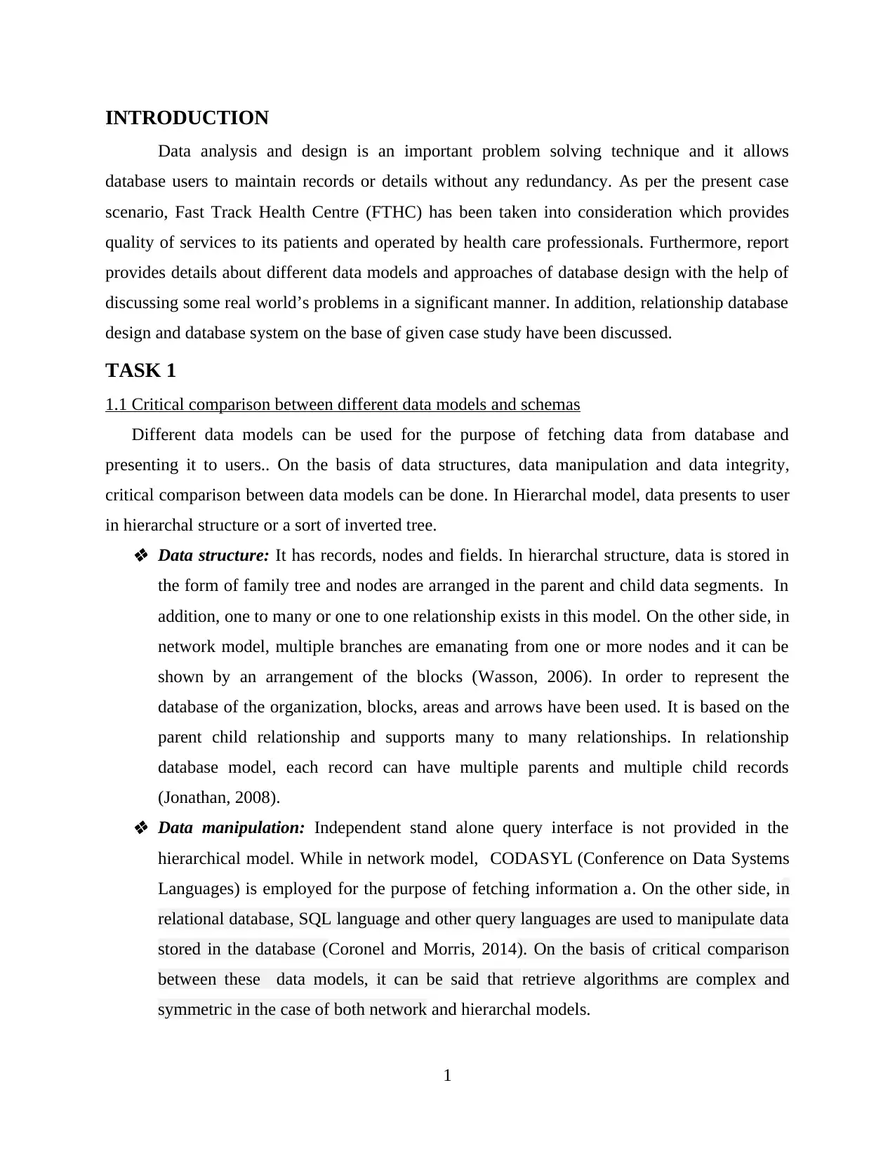
1.1 Critical comparison between different data models and schemas
Different data models can be used for the purpose of fetching data from database and
presenting it to users.. On the basis of data structures, data manipulation and data integrity,
critical comparison between data models can be done. In Hierarchal model, data presents to user
in hierarchal structure or a sort of inverted tree. Data structure: It has records, nodes and fields. In hierarchal structure, data is stored in
the form of family tree and nodes are arranged in the parent and child data segments. In
addition, one to many or one to one relationship exists in this model. On the other side, in
network model, multiple branches are emanating from one or more nodes and it can be
shown by an arrangement of the blocks (Wasson, 2006). In order to represent the
database of the organization, blocks, areas and arrows have been used. It is based on the
parent child relationship and supports many to many relationships. In relationship
database model, each record can have multiple parents and multiple child records
(Jonathan, 2008). Data manipulation: Independent stand alone query interface is not provided in the
hierarchical model. While in network model, CODASYL (Conference on Data Systems
Languages) is employed for the purpose of fetching information a. On the other side, in
relational database, SQL language and other query languages are used to manipulate data
stored in the database (Coronel and Morris, 2014). On the basis of critical comparison
between these data models, it can be said that retrieve algorithms are complex and
symmetric in the case of both network and hierarchal models.
1
Data analysis and design is an important problem solving technique and it allows
database users to maintain records or details without any redundancy. As per the present case
scenario, Fast Track Health Centre (FTHC) has been taken into consideration which provides
quality of services to its patients and operated by health care professionals. Furthermore, report
provides details about different data models and approaches of database design with the help of
discussing some real world’s problems in a significant manner. In addition, relationship database
design and database system on the base of given case study have been discussed.
TASK 1
1.1 Critical comparison between different data models and schemas
Different data models can be used for the purpose of fetching data from database and
presenting it to users.. On the basis of data structures, data manipulation and data integrity,
critical comparison between data models can be done. In Hierarchal model, data presents to user
in hierarchal structure or a sort of inverted tree. Data structure: It has records, nodes and fields. In hierarchal structure, data is stored in
the form of family tree and nodes are arranged in the parent and child data segments. In
addition, one to many or one to one relationship exists in this model. On the other side, in
network model, multiple branches are emanating from one or more nodes and it can be
shown by an arrangement of the blocks (Wasson, 2006). In order to represent the
database of the organization, blocks, areas and arrows have been used. It is based on the
parent child relationship and supports many to many relationships. In relationship
database model, each record can have multiple parents and multiple child records
(Jonathan, 2008). Data manipulation: Independent stand alone query interface is not provided in the
hierarchical model. While in network model, CODASYL (Conference on Data Systems
Languages) is employed for the purpose of fetching information a. On the other side, in
relational database, SQL language and other query languages are used to manipulate data
stored in the database (Coronel and Morris, 2014). On the basis of critical comparison
between these data models, it can be said that retrieve algorithms are complex and
symmetric in the case of both network and hierarchal models.
1
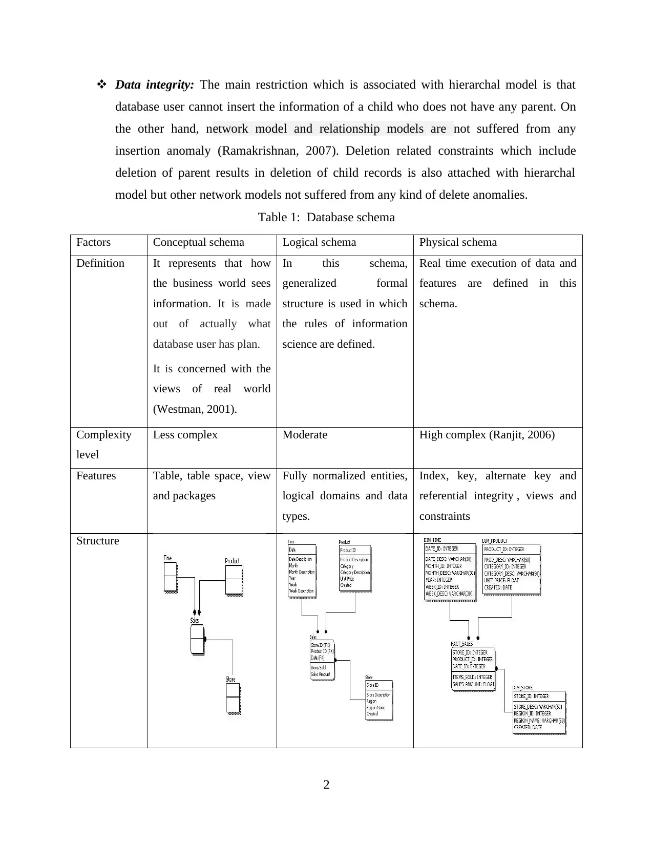
Data integrity: The main restriction which is associated with hierarchal model is that
database user cannot insert the information of a child who does not have any parent. On
the other hand, network model and relationship models are not suffered from any
insertion anomaly (Ramakrishnan, 2007). Deletion related constraints which include
deletion of parent results in deletion of child records is also attached with hierarchal
model but other network models not suffered from any kind of delete anomalies.
Table 1: Database schema
Factors Conceptual schema Logical schema Physical schema
Definition It represents that how
the business world sees
information. It is made
out of actually what
database user has plan.
It is concerned with the
views of real world
(Westman, 2001).
In this schema,
generalized formal
structure is used in which
the rules of information
science are defined.
Real time execution of data and
features are defined in this
schema.
Complexity
level
Less complex Moderate High complex (Ranjit, 2006)
Features Table, table space, view
and packages
Fully normalized entities,
logical domains and data
types.
Index, key, alternate key and
referential integrity , views and
constraints
Structure
2
⊘ This is a preview!⊘
Do you want full access?
Subscribe today to unlock all pages.
Trusted by 1+ million students worldwide
1.2 Critical discussion of benefits and limitations of different database technologies
In earlier, most of the enterprises were used traditionalfile system for storing and
managing information. Less complexity and high security related advantages are associated with
the use of file system. However, data redundancy issue, high access time and data integrity
related challenges are also associated with the use of traditional file system. For example, in file
system, each application has its own private file and it leads to considerable redundancy (Ault,
2002.).By using centralized database this type of problem can be reduced but it can be possible
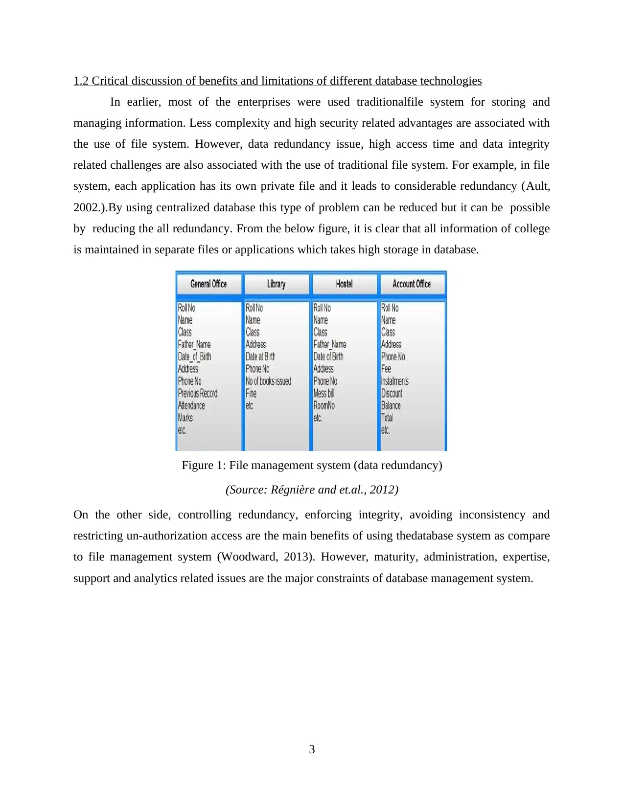
by reducing the all redundancy. From the below figure, it is clear that all information of college
is maintained in separate files or applications which takes high storage in database.
Figure 1: File management system (data redundancy)
(Source: Régnière and et.al., 2012)
On the other side, controlling redundancy, enforcing integrity, avoiding inconsistency and
restricting un-authorization access are the main benefits of using thedatabase system as compare
to file management system (Woodward, 2013). However, maturity, administration, expertise,
support and analytics related issues are the major constraints of database management system.
3
In earlier, most of the enterprises were used traditionalfile system for storing and
managing information. Less complexity and high security related advantages are associated with
the use of file system. However, data redundancy issue, high access time and data integrity
related challenges are also associated with the use of traditional file system. For example, in file
system, each application has its own private file and it leads to considerable redundancy (Ault,
2002.).By using centralized database this type of problem can be reduced but it can be possible
by reducing the all redundancy. From the below figure, it is clear that all information of college
is maintained in separate files or applications which takes high storage in database.
Figure 1: File management system (data redundancy)
(Source: Régnière and et.al., 2012)
On the other side, controlling redundancy, enforcing integrity, avoiding inconsistency and
restricting un-authorization access are the main benefits of using thedatabase system as compare
to file management system (Woodward, 2013). However, maturity, administration, expertise,
support and analytics related issues are the major constraints of database management system.
3
Paraphrase This Document
Need a fresh take? Get an instant paraphrase of this document with our AI Paraphraser
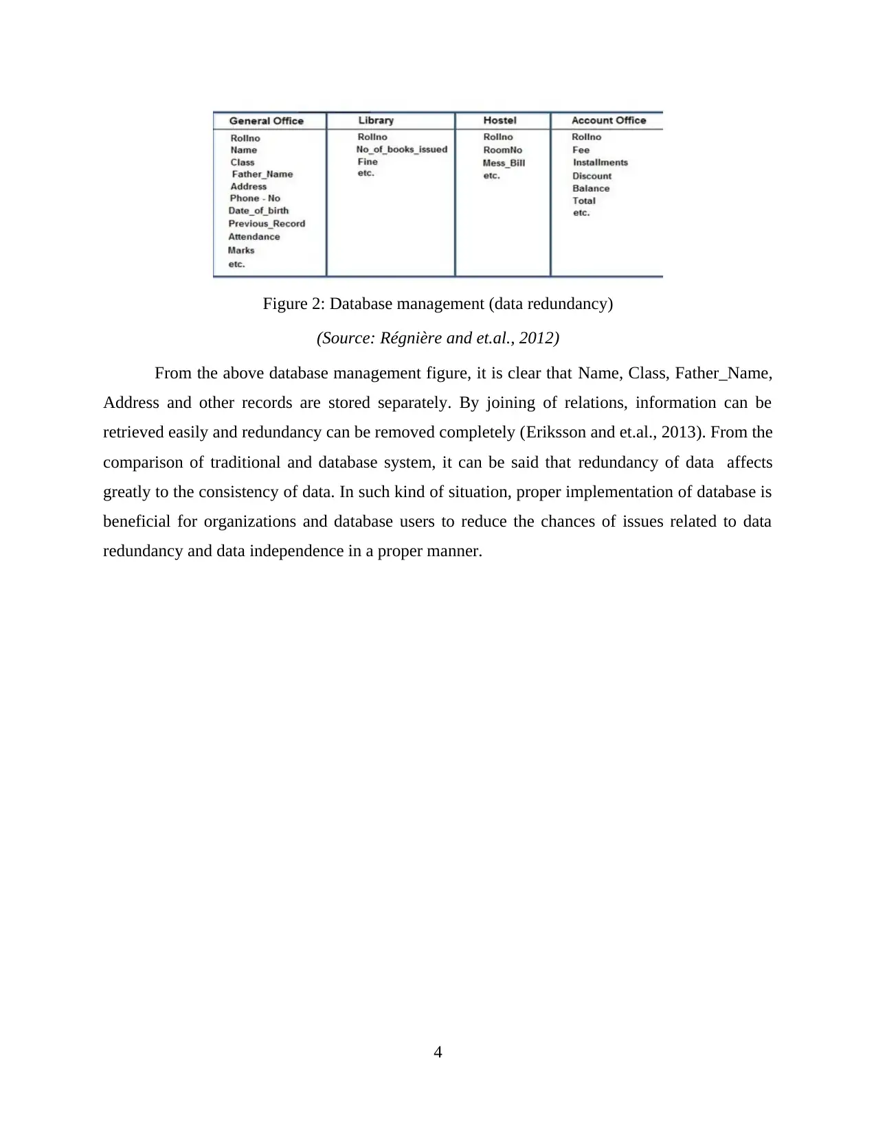
Figure 2: Database management (data redundancy)
(Source: Régnière and et.al., 2012)
From the above database management figure, it is clear that Name, Class, Father_Name,
Address and other records are stored separately. By joining of relations, information can be
retrieved easily and redundancy can be removed completely (Eriksson and et.al., 2013). From the
comparison of traditional and database system, it can be said that redundancy of data affects
greatly to the consistency of data. In such kind of situation, proper implementation of database is
beneficial for organizations and database users to reduce the chances of issues related to data
redundancy and data independence in a proper manner.
4
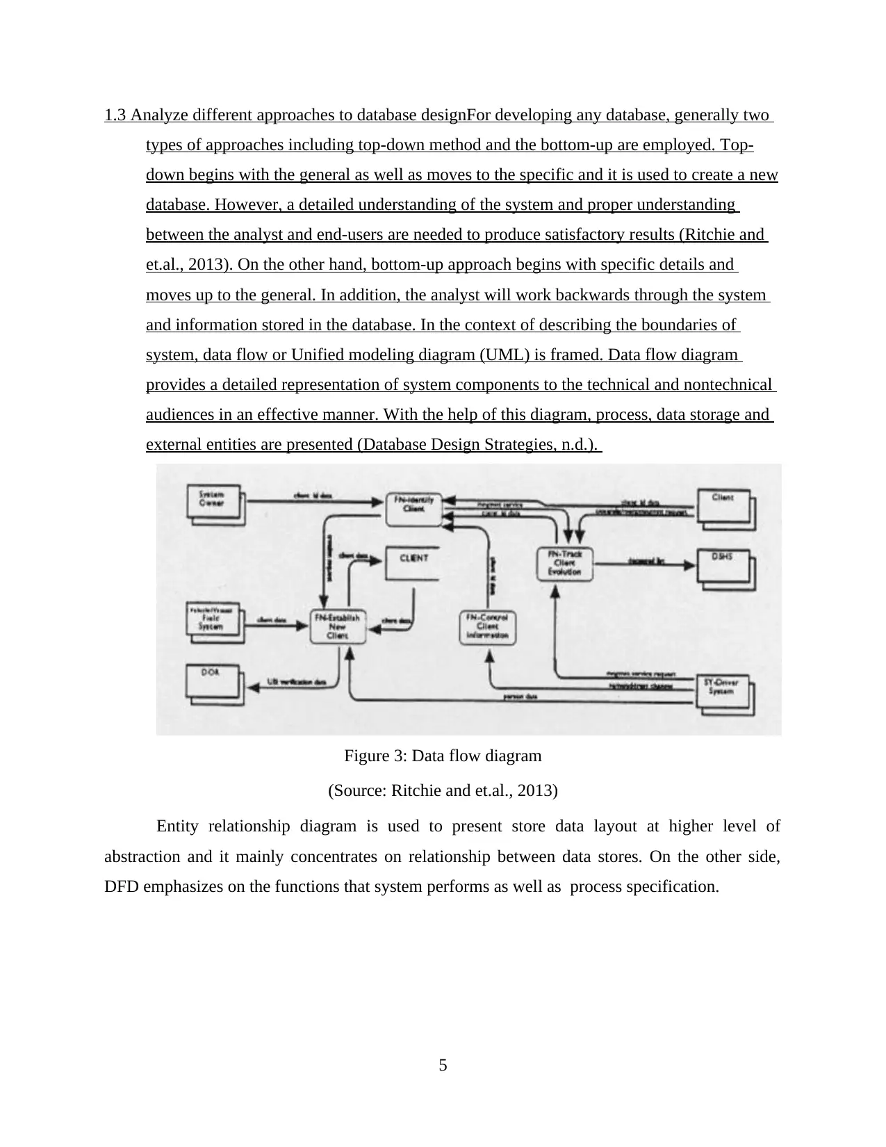
1.3 Analyze different approaches to database designFor developing any database, generally two
types of approaches including top-down method and the bottom-up are employed. Top-
down begins with the general as well as moves to the specific and it is used to create a new
database. However, a detailed understanding of the system and proper understanding
between the analyst and end-users are needed to produce satisfactory results (Ritchie and
et.al., 2013). On the other hand, bottom-up approach begins with specific details and
moves up to the general. In addition, the analyst will work backwards through the system
and information stored in the database. In the context of describing the boundaries of
system, data flow or Unified modeling diagram (UML) is framed. Data flow diagram
provides a detailed representation of system components to the technical and nontechnical
audiences in an effective manner. With the help of this diagram, process, data storage and
external entities are presented (Database Design Strategies, n.d.).
Figure 3: Data flow diagram
(Source: Ritchie and et.al., 2013)
Entity relationship diagram is used to present store data layout at higher level of
abstraction and it mainly concentrates on relationship between data stores. On the other side,
DFD emphasizes on the functions that system performs as well as process specification.
5
⊘ This is a preview!⊘
Do you want full access?
Subscribe today to unlock all pages.
Trusted by 1+ million students worldwide
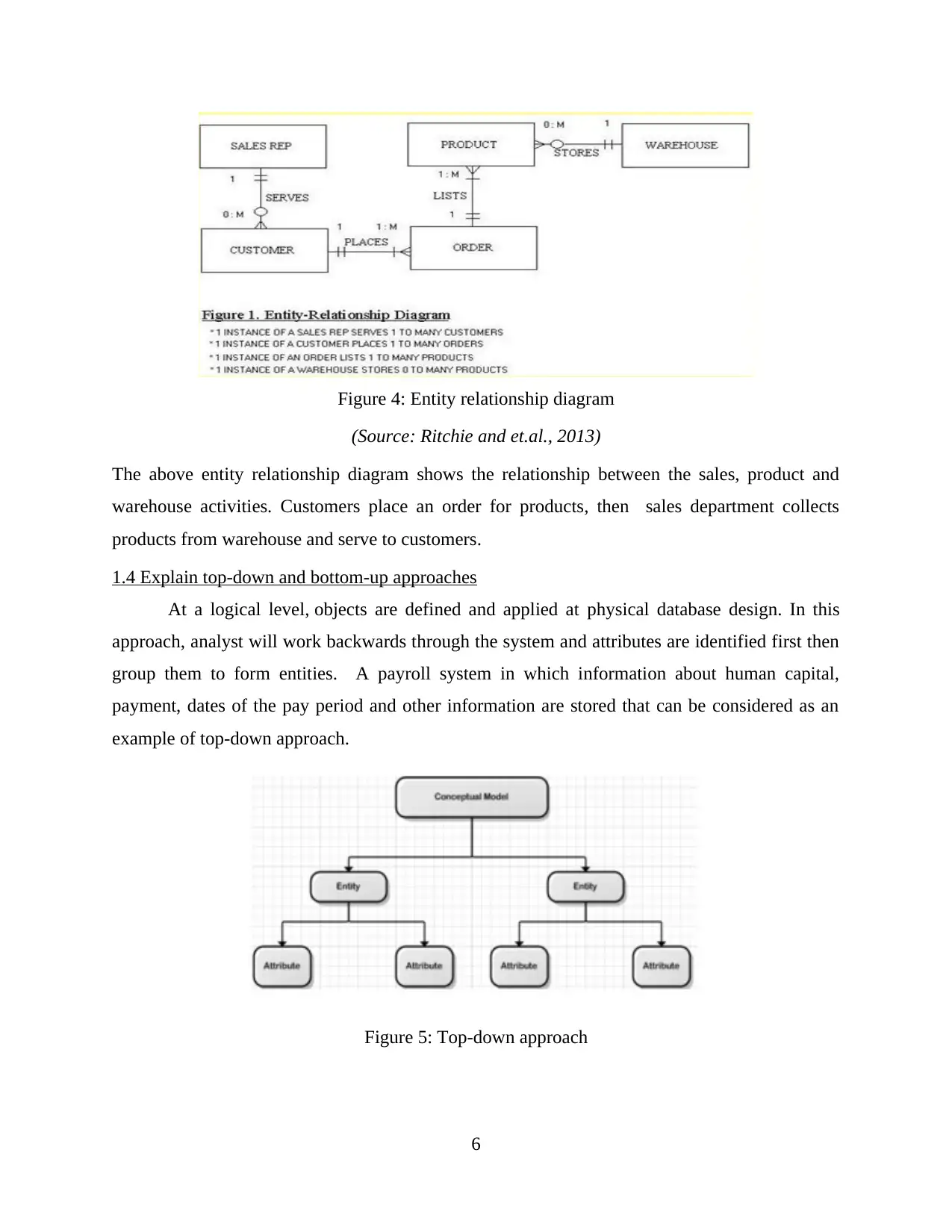
Figure 4: Entity relationship diagram
(Source: Ritchie and et.al., 2013)
The above entity relationship diagram shows the relationship between the sales, product and
warehouse activities. Customers place an order for products, then sales department collects
products from warehouse and serve to customers.
1.4 Explain top-down and bottom-up approaches
At a logical level, objects are defined and applied at physical database design. In this
approach, analyst will work backwards through the system and attributes are identified first then
group them to form entities. A payroll system in which information about human capital,
payment, dates of the pay period and other information are stored that can be considered as an
example of top-down approach.
Figure 5: Top-down approach
6
Paraphrase This Document
Need a fresh take? Get an instant paraphrase of this document with our AI Paraphraser
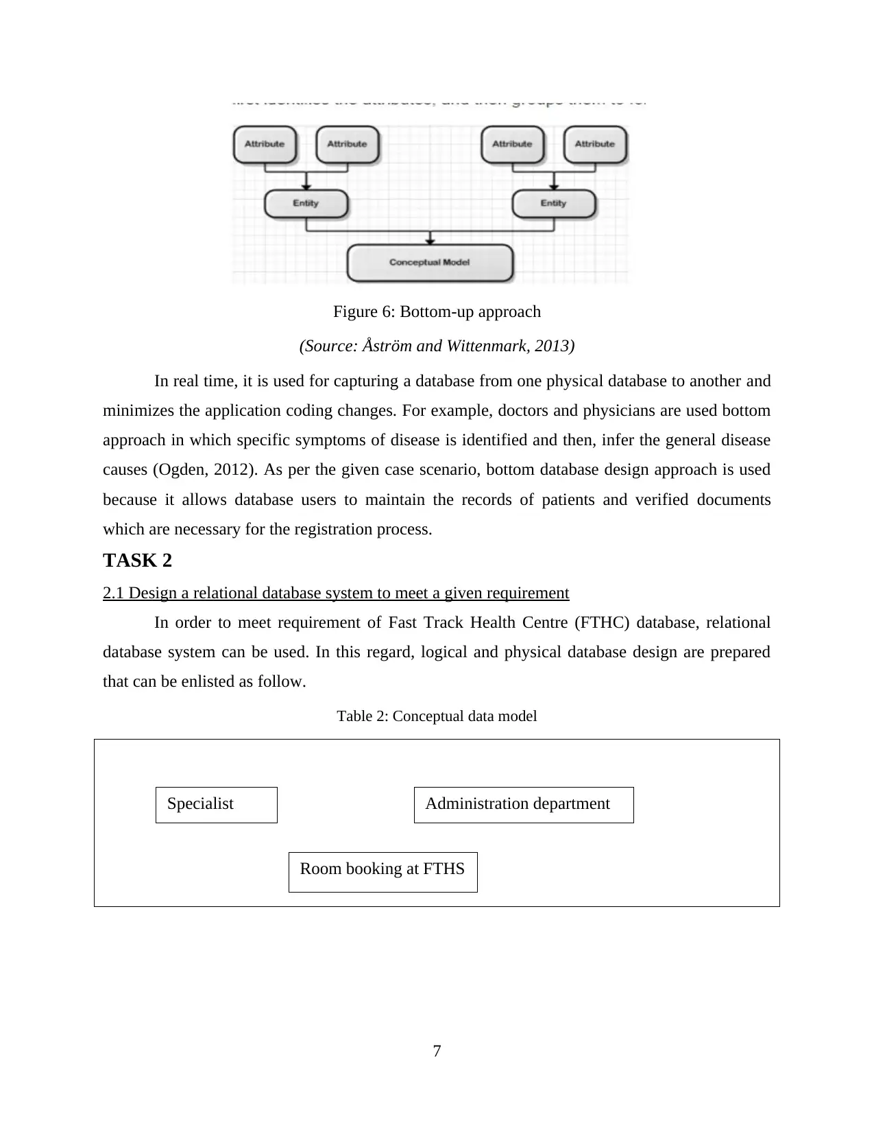
Figure 6: Bottom-up approach
(Source: Åström and Wittenmark, 2013)
In real time, it is used for capturing a database from one physical database to another and
minimizes the application coding changes. For example, doctors and physicians are used bottom
approach in which specific symptoms of disease is identified and then, infer the general disease
causes (Ogden, 2012). As per the given case scenario, bottom database design approach is used
because it allows database users to maintain the records of patients and verified documents
which are necessary for the registration process.
TASK 2
2.1 Design a relational database system to meet a given requirement
In order to meet requirement of Fast Track Health Centre (FTHC) database, relational
database system can be used. In this regard, logical and physical database design are prepared
that can be enlisted as follow.
Table 2: Conceptual data model
7
Specialist
detail
Administration department
Room booking at FTHS
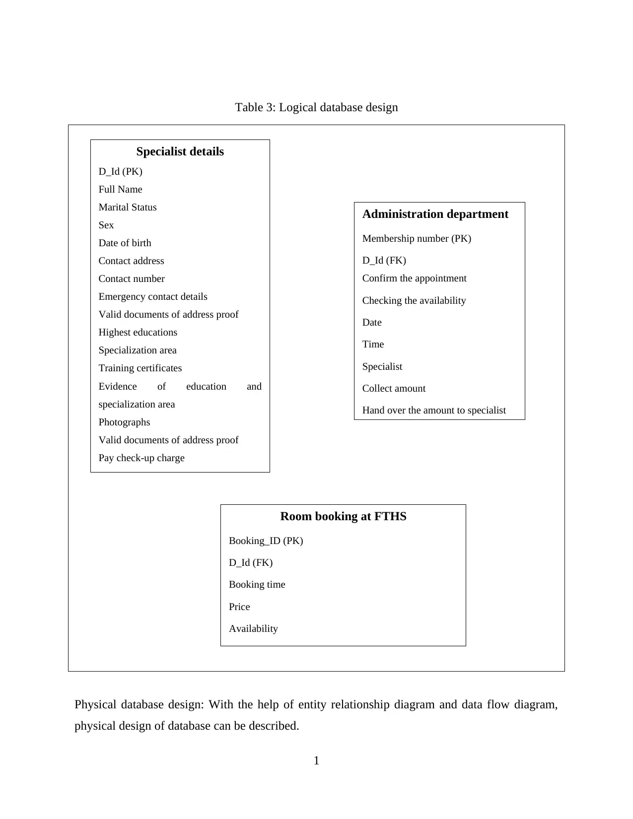
Table 3: Logical database design
Physical database design: With the help of entity relationship diagram and data flow diagram,
physical design of database can be described.
1
Specialist details
D_Id (PK)
Full Name
Marital Status
Sex
Date of birth
Contact address
Contact number
Emergency contact details
Valid documents of address proof
Highest educations
Specialization area
Training certificates
Evidence of education and
specialization area
Photographs
Valid documents of address proof
Pay check-up charge
Room booking at FTHS
Booking_ID (PK)
D_Id (FK)
Booking time
Price
Availability
Administration department
Membership number (PK)
D_Id (FK)
Confirm the appointment
Checking the availability
Date
Time
Specialist
Collect amount
Hand over the amount to specialist
⊘ This is a preview!⊘
Do you want full access?
Subscribe today to unlock all pages.
Trusted by 1+ million students worldwide
1 out of 23
Related Documents


Your All-in-One AI-Powered Toolkit for Academic Success.
+13062052269
info@desklib.com
Available 24*7 on WhatsApp / Email
![[object Object]](/_next/static/media/star-bottom.7253800d.svg)
Unlock your academic potential
Copyright © 2020–2026 A2Z Services. All Rights Reserved. Developed and managed by ZUCOL.