Data Modelling, Management and Governance Report - School Database
VerifiedAdded on 2023/06/08
|31
|6642
|361
Report
AI Summary
This report provides a comprehensive overview of data modeling management and governance, focusing on the development of a database system for a local secondary school. It includes a UML use case diagram illustrating the interactions between staff and students with the system, an entity-relationship diagram (ERD) detailing the relationships between entities like students, staff, and subjects, and the conversion of a logical ERD into a physical ERD. The report also features SQL queries for data access and information retrieval, demonstrating how to manage and manipulate data within the designed database system. The goal is to provide a blueprint for the school's database system, ensuring efficient data storage, accessibility, and management.

DATA MODELLING
MANAGEMENT AND
GOVERNANCE
1
MANAGEMENT AND
GOVERNANCE
1
Paraphrase This Document
Need a fresh take? Get an instant paraphrase of this document with our AI Paraphraser
TABLE OF CONTENTS
INTRODUCTION...........................................................................................................................3
MAIN BODY...................................................................................................................................3
1. UML use case diagram................................................................................................................3
Use case relationship...................................................................................................................6
Benefits of use case diagram.......................................................................................................7
2. Entity relationship diagram for school scenario..........................................................................9
Database system diagram...........................................................................................................16
3. Logical design (ERD) and physical design................................................................................18
4.SQL Queries................................................................................................................................23
CONCLUSION..............................................................................................................................28
REFERENCES..............................................................................................................................30
INTRODUCTION
Data modelling refer to the process of developing the simplified diagram of the software
system which contains the data elements and other symbols etc. and it also shows how the data
flows within the system (Liu and et.al 2020). Data modelling is all about to generating the
blueprint for the desired database system or reengineering with the legacy applications. It
comprises of the visual representation of the complete information system or to communicate the
associativity between every data point aspects. data models can be developed around the
requirement of business. There are specific data models which the user concerns with conceptual
data model, logical data model and physical data model. Where it gives the clear image about the
data entities along with its various attributes (Sawaneh and et.al 2018). Database management
system refers to the computerised data storing system where the data is available in the arranged
or organised form that can be easily retrieved and accessed. Every business has their individual
data base system where they store their business details and other critical information, for
accessing the data they are provided with particular authentication in order to protect data from
any malicious activities. Data model generally examine the structured data that keeps the
persistent data within the relational database system and it is specified within the data modelling
language.
Following report will cover the description about the UML use case diagram that will be
made for the local secondary school in Luton who is looking forward to develop the database
system that comprises of all their useful details and other information. It will cover the Entity
relationship diagram where it will also highlight the conversion of logical ERD into physical
ERD and also covers the SQL queries for data access and information retrieval.
MAIN BODY
1. UML use case diagram
Unified modelling language diagram assists in providing the visual aspects of the system,
it generally describes the quantifiable factors about the system which is discussed visually like
relationship, behaviour and its cardinality, functionality (Zhidchenko and et.al 2021). UML is
utilised as the modelling of the system that is independent of the language platform, it provides
the standard approaches for write down the system models that consists of the conceptual ideas.
It is further classified into the categories that are on the basis of the structure where it covers the
3
⊘ This is a preview!⊘
Do you want full access?
Subscribe today to unlock all pages.
Trusted by 1+ million students worldwide
Class diagram, composite structural diagram, object diagram and component diagram. While
other category is behavioural diagram where it covers the state machine diagram, activity
diagram, use case diagram and sequence diagram, timing diagram. UML diagram offers the
greater flexibility as it is one of the common used and widely accepted language for the outlining
programs.
UML use case diagram refers to depicting the functionality about the system and for its
components. These diagram are most commonly used diagram in order to describe the functional
requirements about the system and its interaction with the system users (Fischer, Scholten, and
Unwin, 2019). This diagram uses the set of use cases where it also involves the actor and their
relationship, it describes the different scenarios from which the system is used, it provides the
greater level view about the system. Main purpose of use case diagram is to specify the context
of the syst4em and to capture the system essential requirement, it also validates the architecture
of system and drive the execution or deliver the test cases. For the local school case scenario, it is
provided with the details that the school wants to develop their database system where they can
store the details of their staff, students and subjects. It comprises of the aspects that are as
follows:
Actor: Actors, someone or other external hardware system who interacts with the system and
they have crucial role in the business they are similar to the user but user can play other different
roles. They generally trigger the use case and play their role towards the system to enter the input
within the system in order to get the output. Regarding the school scenario two actors are
identified as student (pupil) and staff.
Use case: System functions that is process (automated or manual), every actor is required to
associates with the use case while some of the use cases might not associates with the actors.
Paraphrase This Document
Need a fresh take? Get an instant paraphrase of this document with our AI Paraphraser
Communication link: Participation of the actor within the use case system is represented by the
solid link, that generally associates the use case with the actor. With the help of this actors are
connected with the use case and also indicates the communication as how actor is
communicating with the use case (Mehta and et.al 2021). Thus connector helps in specifying that
particular actor has the role within the system. For an instance for school scenario in use case
diagram it will show how pupil can access the system and can take the subjects, also shows how
staff access the system and perform their specific role within the system.
System boundary: System boundary indicates the entire system where it describes the required
documents. For the large size and complicated system every module is considered as the system
boundary.
5
Use case relationship
Use case shares the distinct type of relationship where decision regarding relationship between
the two use cases is taken by the software analysts of that particular use case diagram. Where the
relationship between the two use cases is generally consider as modelling the dependency among
the use cases (Revesz, Rashid and Tuyishime, 2019). By reusing the use case with the different
kind of relationship is effective as it decreases the efforts that is needed for constructing the
system. Some of the use case relationship are as follows:
Extend: This relationship can be used as to specify that the particular use case is extending the
behaviour of the other use case. Such type of relationship helps in disclosing the information
about the application which generally do not appears and hidden within the use case.
Include: Include relationship is found when the use case is presented as using the functionality
and other aspects of the other use case. It is depicted by the directed arrow with having the dotted
line.
⊘ This is a preview!⊘
Do you want full access?
Subscribe today to unlock all pages.
Trusted by 1+ million students worldwide
Benefits of use case diagram
There are various advantages of use case diagram which assists the software developer to design
their process as per the user’s perspective. As an outcome system works more efficiently and
helps in achieving the user’s goals (Utomo,Cahyono and Tristono, 2019). There are other
benefits of use case diagram is as follows:
This diagram is usually traceable; it provides the information about structure as well as
system behaviour.
It assists in analysing the complete functional requirements about the system so desired
result can come out.
Its simplicity and easy interface lead the businesses to easily commence with and use
case also compatible for the software developer to deliver end result to their end users.
They are reusable in project and it captures all the requirements for every iteration within
a creation guidance for the programmers, within test cases and also in user
documentation.
Use cases are also useful for the scoping and it also make easier or simpler for the project
to undertake the phased approaches for the delivery, it can be easily removes and added
from the software projects when the priorities changes (Wajszczyk and Gruszka, 2020).
Every use case defines the one approach for system is being used but additionally use
case modelling also helps in explaining the things which are not correct. Identification of
the exception points to the successful scenario in initial phase within a project is quite
helpful and saves a lot of time by determining the appropriate requirements.
Its major advantage is that it is written in the natural language that means it can be easily
understood as well as it gives the easier way for communication and interaction with the
users. It also helpful is managing the complexity of the large projects by simply
decomposing the issue within a different functions and can be easily specified by the
user’s perception.
7
Paraphrase This Document
Need a fresh take? Get an instant paraphrase of this document with our AI Paraphraser
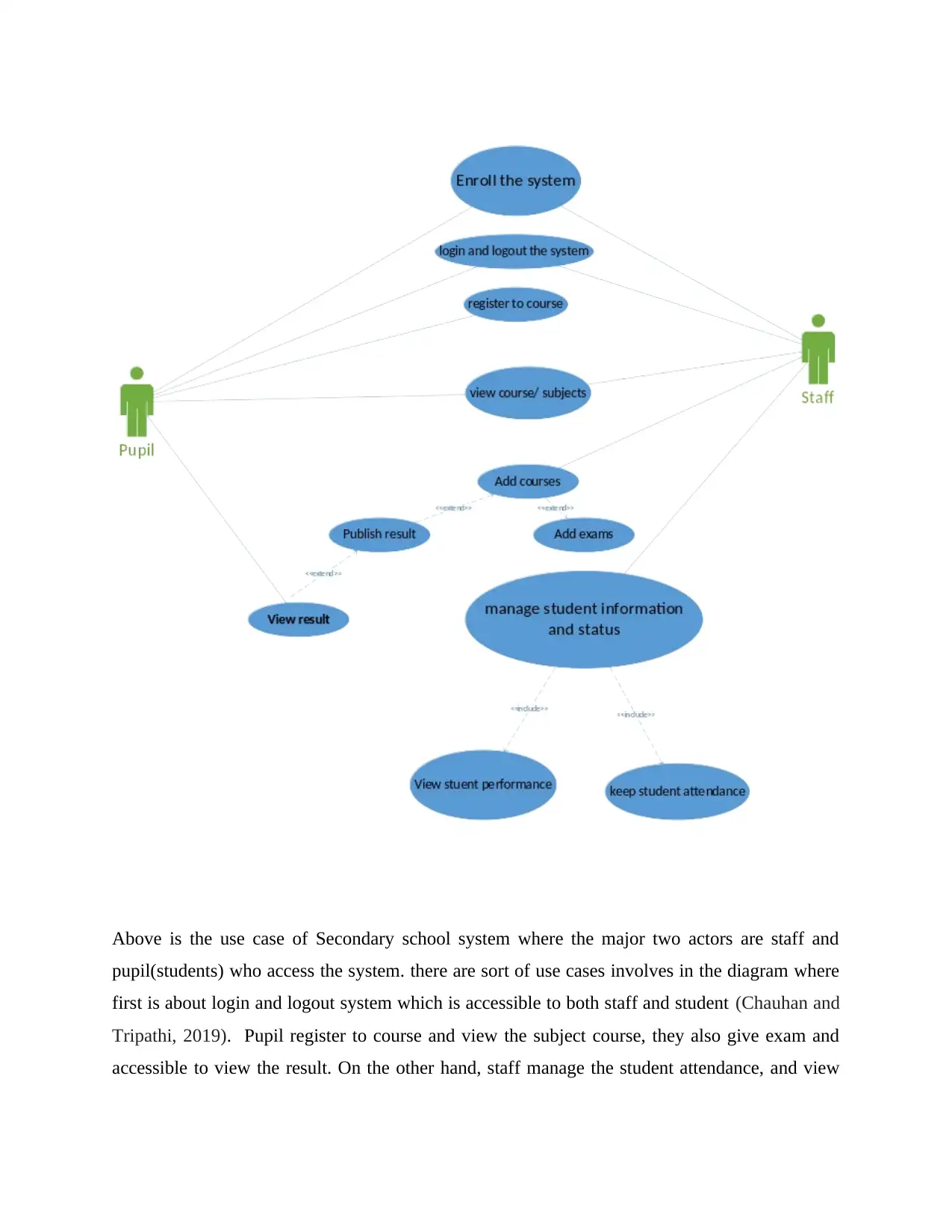
Above is the use case of Secondary school system where the major two actors are staff and
pupil(students) who access the system. there are sort of use cases involves in the diagram where
first is about login and logout system which is accessible to both staff and student (Chauhan and
Tripathi, 2019). Pupil register to course and view the subject course, they also give exam and
accessible to view the result. On the other hand, staff manage the student attendance, and view
the student performance, they also add the subjects and takes exam also manage the student
information. It also involves the include and extended relationship for the use cases.
2. Entity relationship diagram for school scenario
Entity relationship diagram defines the interrelated things that are present in specific domain, it
is the type of structural diagram in the database designing system where it shows the relationship
between the different entities. It shows the relationship among the user, objects and other
concepts in an information technology system (Osborne, 2020). It is mostly use for designing or
debugging the relational database system, it uses the defined set of symbols like rectangles, oval
and associativity lines all have importance in ER diagram. It consists of three major things that
are entities, attributes and relationship.
Entity: Entities define as the person, object or other concept for that the data have been stored, it
is the table that are used in the database system for storing the information. It simply presented
with the help of the rectangles. It is the real world object that is distinguished from the other
objects.
Weak entity: Weak entity an entity which usually relies on the existence of the other entity, in
technical terms it can be understood as the entity which cannot be easily determined by its own
attributes. In this it takes the use of foreign key that combines with its attribute to develop the
primary key (Fatmawati and Munajat, 2018).
9
⊘ This is a preview!⊘
Do you want full access?
Subscribe today to unlock all pages.
Trusted by 1+ million students worldwide
There are other types of entities that are as follows:
Independent entity: These type of entities is considering as the kernels which also understood as
the backbone of database system, they are the things on which the other tables based on
(Peleshchyshyn and et.al 2018). It has some characteristics that are as follows:
Building block of the system
Primary key can be simple and composite as well
Primary key cannot be a foreign key
They generally don’t rely on other entity for its existence
Dependent entity: It is also called as the derived entities which rely on another table for its
meaning. There are some characteristics of dependent entities is as follows:
These entities are used for associating the two kernels together
They are considering as to depend on two or more other tables
In this many to many cardinality becomes the linkage tables with at least two foreign
keys.
They also consist of other attributes
In this foreign key determines every associated table
In this generally there are three options for the primary key, utilise the composite of the foreign
keys of the linked tables if it is unique or to develop new simple primary key.
Attributes: These are referring to the characteristics of the entities, ERD attributes also
represented as the primary key which determines the unique attribute that can easily assigned to
the other attributes as well. It involves the details of Entity which are highlighted in the
conceptual entity relationship model diagram (Roy-Hubara and Sturm, 2020). It is simply
represented in an oval shape so that user can easily identify that particular things present in an
oval shape are attributes that carries the detailed information about entities.
Paraphrase This Document
Need a fresh take? Get an instant paraphrase of this document with our AI Paraphraser
It further involves the concept that are key attribute and partial key attribute. Where key
attribute is uniquely identifying in every entity within an entity set it is represented by
underlining the attribute (Bjeladinovic, 2018). Key attribute also represented as the primary key
which is unique for every entity. Whereas partial key attribute is to identify the weak entity.
Composite attribute: When an attribute is generally composed of more than one attribute than
it is termed as the composite attribute. It can also be understood as the attribute that divides into
other sub parts. For an example in school case scenario it involves the attribute which is
student_address so in this address attribute can further divide in other sub attributes that are city,
street, country an state.
11
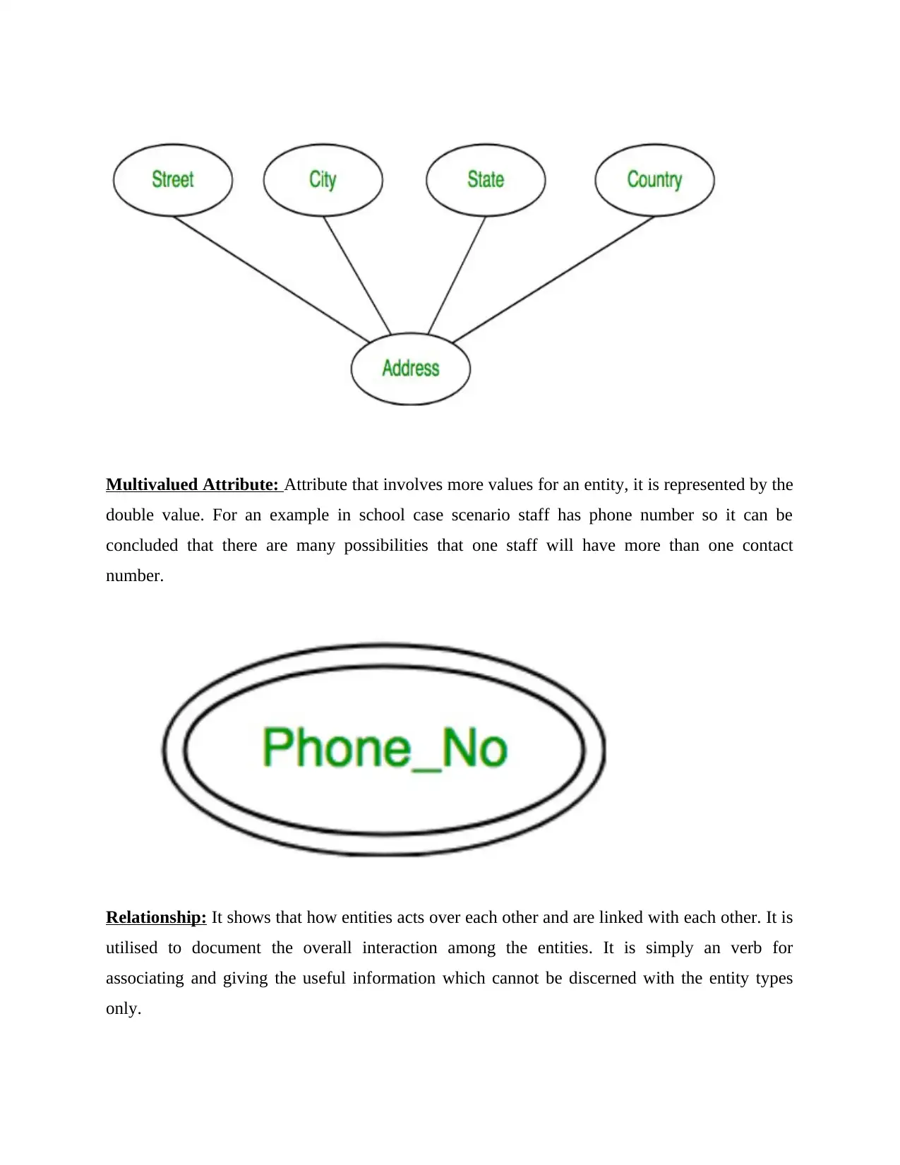
Multivalued Attribute: Attribute that involves more values for an entity, it is represented by the
double value. For an example in school case scenario staff has phone number so it can be
concluded that there are many possibilities that one staff will have more than one contact
number.
Relationship: It shows that how entities acts over each other and are linked with each other. It is
utilised to document the overall interaction among the entities. It is simply an verb for
associating and giving the useful information which cannot be discerned with the entity types
only.
⊘ This is a preview!⊘
Do you want full access?
Subscribe today to unlock all pages.
Trusted by 1+ million students worldwide
1 out of 31
Related Documents


Your All-in-One AI-Powered Toolkit for Academic Success.
+13062052269
info@desklib.com
Available 24*7 on WhatsApp / Email
![[object Object]](/_next/static/media/star-bottom.7253800d.svg)
Unlock your academic potential
Copyright © 2020–2026 A2Z Services. All Rights Reserved. Developed and managed by ZUCOL.