Biomedical Software Company: IP Address Planning and Subnetting
VerifiedAdded on 2023/05/28
|11
|2273
|348
Report
AI Summary
This report presents an IP address planning strategy for a biomedical software development company with a headquarters and two branches. The report details the allocation of IPv4 and IPv6 addresses, subnet masks, network addresses, broadcast addresses, and default gateways for each subnet. It covers the number of devices in each location and the rationale behind the subnetting decisions. The report includes calculations for subnet masks, the number of usable hosts, and a logical network diagram. It also provides a physical network diagram in the appendix. The assignment aims to demonstrate the understanding of IP addressing, subnetting, and network design principles.

DATA COMMUNICATIONS AND NETWORKS
Biomedical Software Development Company IP Address Planning
[DATE]
[Author]
Biomedical Software Development Company IP Address Planning
[DATE]
[Author]
Paraphrase This Document
Need a fresh take? Get an instant paraphrase of this document with our AI Paraphraser

Summary
All the computers located on the internetwork ought to have an IP address. It is not uniquely or
automatically encoded into the interface of the network of a computer. The administrator of the
network assigns the IP address either dynamically or statically. Due to this, there ought to be a
careful IP address management to prevent issues raised by addresses that might be duplicated.
The IP address is represented in a notation of a dotted decimal in a 32 bit (4-byte) form number
that is shown in the form of 192.168.153.101. The internetwork comprises of networks that are
linked together by the use of devices such as the routers or/and gateways. The computers
effectively comprises of two interfaces of the network which are familiar with the IP addresses
that are utilized on the networks linked with each of the interfaces. The IP addresses transmits
the packets of the IP to the respective network. When the data is transferred from the source
computer to the destination device, it passes through a number of gateways or routers and uses
several network protocols to ensure that the data is secure and has not been interfered with.
During data transmission between the networks, IP address is used to route the data.

Contents
Introduction...............................................................................................................................................3
Biomedical Software Development Company.........................................................................................3
Address allocation plan for each subnet..................................................................................................4
IP addressing plan for IP V4................................................................................................................4
IPv4 allocation plan for Head Quarter............................................................................................4
IPv4 allocation plan for Branch A....................................................................................................4
IPv4 allocation plan for Branch B....................................................................................................5
IP addressing plan for IP V6................................................................................................................6
IPv6 allocation plan for Head Quarter............................................................................................6
IPv6 allocation plan for Branch A....................................................................................................6
IPv6 allocation plan for Branch B....................................................................................................7
Complete Diagram including IP address subnetting..............................................................................7
Conclusion..................................................................................................................................................8
References..................................................................................................................................................8
Appendix A................................................................................................................................................8
⊘ This is a preview!⊘
Do you want full access?
Subscribe today to unlock all pages.
Trusted by 1+ million students worldwide

Introduction
The internet that we use almost daily to complete some of our day to day activities actually is
network of networks. It is a virtual world whereby all the computers on the internet are seen as to
be in connection with every other computer on the internet. The internet is held together by the
internet protocol (IP). It offers the best methods for transporting datagrams to the destination
from the source regardless of the position of the networks in the machines whereby they may be
located on the same network or other networks may be between the networks. The IP also routes
packets of data between the networks and IP addresses. It also specifies the source and
destination nodes’ location in the routing system topology. The IP address may be obtained
automatically whereby the computer locates the DHCP server itself in the network and assigns it
dynamically or it can also be assigned manually to the present interface of the network. It is
divided into three entries, that is, the IP address assigned in the current interface of the network,
subnet mask that is automatically done by the computer but can also be manually assigned and
finally the default gateway which is used to connect a computer with the other networks.
This is what it entails in this report whereby we are going to plan the IP addressing of a
biomedical software development company. The IP addresses will be assigned to the routers,
printers, servers, computers among other end devices. We will also determine their subnet
masks, broadcast addresses, network addresses and their specific IP addresses (Odom, 2013).
Biomedical Software Development Company
This biomedical company is located in Gold Coast. The company has two branches and the head
quarter. The head quarter has 719 network devices, branch A has 71 network devices while
branch B has 79 network devices. The branches are connected together using a LAN network
that enables centralization of management since resources can be shared over the network. For
example, while developing a software, different modules may be assigned to different
individuals on the network and once a module has been completed, it is sent over the network to
the person in charge of the whole software where they are combined to develop the full software.
In case of printed materials that need to be shared in the network, they are efficiently sent over
the network from the printers to the destination. The IT department configures all the networks
using IPV4 and or IPV6 IP.
Paraphrase This Document
Need a fresh take? Get an instant paraphrase of this document with our AI Paraphraser

Address allocation plan for each subnet
The following IPv4 IP address planning and allocation can be used for the biomedical software
development company.
IP addressing plan for IP V4
IPv4 allocation plan for Head Quarter
The head quarter has 719 devices that require to be assigned with the IP addresses of the IPV4.
The IP address allocated for the head quarter is 191.2.71.0. This ip address is of Class B. Class B
networks have a subnet mask of 255.255.0.0 but first we are going to get the number of networks
which in this case is 64 networks. This is obtained by borrowing 6 bits from the host.
Therefore, to obtain the subnet mask, we are going to calculate it as follows:
255.255.0.0 11111111 11111111 00000000 00000000, after borrowing the 6 bits, the following
will be left: 11111111 11111111 11111100 00000000. From the binary number obtained, the
subnet mask becomes, 255.255.252.0.
The number of hosts in this network is 1024 which is obtained from the remaining bits
left in the host but the usable ones are 1022.
In this network, the following will be the plan:
The subnet mask will be: 255.255.252.0
The network address will be: 191.2.68.0
The broadcast address will be: 191.2.71.255
The default gateway will be: 191.2.71.1
The ip addresses will range from: 191.2.68.1 – 191.2.71.254
The IP addresses will be assigned to the computers, printers and server among other devices
(Lammle, 2011).
IPv4 allocation plan for Branch A
Branch A has 71 network devices. It will have an IP address of 172.16.10.2. One can allocate
510 hosts to allow for expansion in the future due to growth. The IP address also falls under
Class B. The number of networks available in this network will be 128 as we are going to borrow

7 bits from the host. The remaining bits will be 9 bits in the host which will give us the 510 hosts
(Cheshire, Aboba and Guttman, 2015).
To obtain the subnet mask, we will calculate it as follows:
255.255.0.0 11111111 11111111 00000000 00000000, after borrowing the 7 bits, the following
will be left: 11111111 11111111 11111110 00000000. From the binary number obtained, the
subnet mask becomes, 255.255.254.0
In this network, the following will be the plan:
The subnet mask will be: 255.255.254.0
The network address will be: 172.16.10.0
The broadcast address will be: 172.16.11.255
The default gateway will be: 172.16.10.1
The ip addresses will range from: 172.16.10.1 – 172.16.11.254
IPv4 allocation plan for Branch B
Branch B has 79 network devices. It will have an IP address of 146.22.16.5. One can allocate
510 hosts to allow for expansion in the future due to growth just like in branch A. The IP address
also falls under Class B. The number of networks available in this network will be 128 as we are
going to borrow 7 bits from the host. The remaining bits will be 9 bits in the host which will give
us the 510 hosts (Hain and Huston, 2015).
To obtain the subnet mask, we will calculate it as follows:
255.255.0.0 11111111 11111111 00000000 00000000, after borrowing the 7 bits, the following
will be left: 11111111 11111111 11111110 00000000. From the binary number obtained, the
subnet mask becomes, 255.255.254.0
In this network, the following will be the plan:
The subnet mask will be: 255.255.254.0
The network address will be: 146.22.16.0
The broadcast address will be: 146.22.17.255
The default gateway will be: 146.22.16.1
The ip addresses will range from: 146.22.16.1 - 146.22.17.254
⊘ This is a preview!⊘
Do you want full access?
Subscribe today to unlock all pages.
Trusted by 1+ million students worldwide

IP addressing plan for IP V6
The following IPv6 IP address planning and allocation can be used for the biomedical software
development company.
IPv6 allocation plan for Head Quarter
The head quarter has the IPV6 network of 2001:1234:ABCD:7100::/56. 56 bits has 256 networks
which accommodates up to trillions of IP addresses. In this address, the first three sections
represent the global routing prefix, that is, 2001:1234:ABCD:, while :7100:, represents the
subnet id and finally :: section represents the interface identifier. So, while subnetting the IPV6,
we will focus on 7100 (Hinden and Deering, 2016).
7100 in binary form will be; 0111 0001 0000 0000. The host utilizes 56 bits, so, after
removing the 56 bits, we will be left with 0000 0000 which will be used in subnetting.
Therefore, the plan for the subnetting will be as follows:
IP subnet and subnet Prefix: 7100/64
Network address: 2001:1234:abcd:7100::
Default Gateway address: 2001:1234:abcd:7101
IP addresses range: 2001:1234:abcd:7100:0000:0000:0000:0000 -
2001:1234:abcd:71ff:ffff:ffff:ffff:ffff
IPv6 allocation plan for Branch A
Branch has the IPV6 network of 2001:DB8:1:2F00::/56. It has 256 networks which
accommodates up to trillions of IP addresses. In this address, the first three sections represent the
global routing prefix, that is, 2001: DB8:1: 2F00:, while :2F00:, represents the subnet id and
finally :: section represents the interface identifier. So, while subnetting the IPV6, we will focus
on 2F00 (Hinden and Deering, 2013)
The plan for the subnetting will be as follows:
IP subnet and subnet Prefix: 2F00/64
Network address: 2001: db8:1: 2F00::
Default Gateway address: 2001: db8:1: 2F00
IP addresses range: 2001:db8:0001:2f00:0000:0000:0000:0000 -
Paraphrase This Document
Need a fresh take? Get an instant paraphrase of this document with our AI Paraphraser
2001:db8:0001:2fff:ffff:ffff:ffff:ffff
IPv6 allocation plan for Branch B
Branch B has the IPV6 network of 2000:ACAD:1234:6600::/56. It has 256 networks which
accommodates up to trillions of IP addresses. In this address, the first three sections represent the
global routing prefix, that is, 2000:ACAD:1234:, while :6600:, represents the subnet id and
finally :: section represents the interface identifier. So, while subnetting the IPV6, we will focus
on 6600 (Wegner, Rockell and Brandon, 2010).
The plan for the subnetting will be as follows:
IP subnet and subnet Prefix: 6600/64
Network address: 2000:acad:1234:6600::
Default Gateway address: 2000:acad:1234:6600
IP addresses range: 2000:acad:1234:6600:0000:0000:0000:0000 -
2000:1234:abcd:66ff:ffff:ffff:ffff:ffff
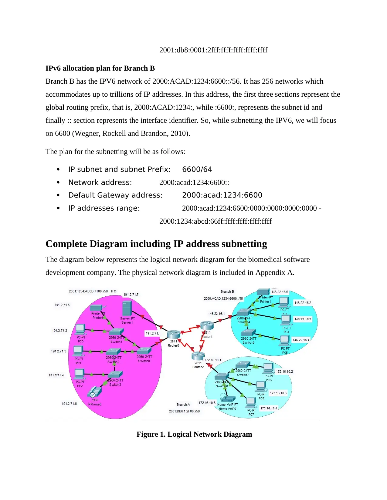
Complete Diagram including IP address subnetting
The diagram below represents the logical network diagram for the biomedical software
development company. The physical network diagram is included in Appendix A.
Figure 1. Logical Network Diagram
IPv6 allocation plan for Branch B
Branch B has the IPV6 network of 2000:ACAD:1234:6600::/56. It has 256 networks which
accommodates up to trillions of IP addresses. In this address, the first three sections represent the
global routing prefix, that is, 2000:ACAD:1234:, while :6600:, represents the subnet id and
finally :: section represents the interface identifier. So, while subnetting the IPV6, we will focus
on 6600 (Wegner, Rockell and Brandon, 2010).
The plan for the subnetting will be as follows:
IP subnet and subnet Prefix: 6600/64
Network address: 2000:acad:1234:6600::
Default Gateway address: 2000:acad:1234:6600
IP addresses range: 2000:acad:1234:6600:0000:0000:0000:0000 -
2000:1234:abcd:66ff:ffff:ffff:ffff:ffff
Complete Diagram including IP address subnetting
The diagram below represents the logical network diagram for the biomedical software
development company. The physical network diagram is included in Appendix A.
Figure 1. Logical Network Diagram

Conclusion
From the report discussed above, it’s clearly observed that IP addressing is a very important
aspect in every organization utilizing networking. This is because it enables smooth
communication between different and connected devices and departments thus enabling smooth
running of the organizations’ activities. Therefore, when it comes to IP addressing, the
administration should be very careful while assigning the IP addresses to various network
devices.
⊘ This is a preview!⊘
Do you want full access?
Subscribe today to unlock all pages.
Trusted by 1+ million students worldwide

References
Cheshire, S., Aboba, B. and Guttman, E., 2015. Dynamic configuration of IPv4 link-local
addresses (No. RFC 3927).
Hain, T. and Huston, G., 2015. A pragmatic report on IPv4 address space consumption. The
Internet Protocol Journal, 8(3), pp.2-19.
Hinden, R. and Deering, S., 2013. Internet protocol version 6 (IPv6) addressing architecture
(No. RFC 3513).
Hinden, R. and Deering, S., 2016. IP version 6 addressing architecture (No. RFC 4291).
Lammle, T., 2011. CCNA Cisco Certified Network Associate Deluxe Study Guide. John Wiley &
Sons.
Odom, W., 2013. CCNA Routing and Switching 200-120 Official Cert Guide Library. Cisco
press.
Wegner, J.D., Rockell, R. and Brandon, C., 2010. IP addressing and subnetting including IPv6.
Syngress Media.
Paraphrase This Document
Need a fresh take? Get an instant paraphrase of this document with our AI Paraphraser

Appendix A
Physical Network Diagram
Physical Network Diagram
1 out of 11
Related Documents


Your All-in-One AI-Powered Toolkit for Academic Success.
+13062052269
info@desklib.com
Available 24*7 on WhatsApp / Email
![[object Object]](/_next/static/media/star-bottom.7253800d.svg)
Unlock your academic potential
Copyright © 2020–2026 A2Z Services. All Rights Reserved. Developed and managed by ZUCOL.