Assessment 1: Database Analysis and Design for Celtic Caterers
VerifiedAdded on 2022/12/15
|21
|2192
|205
Report
AI Summary
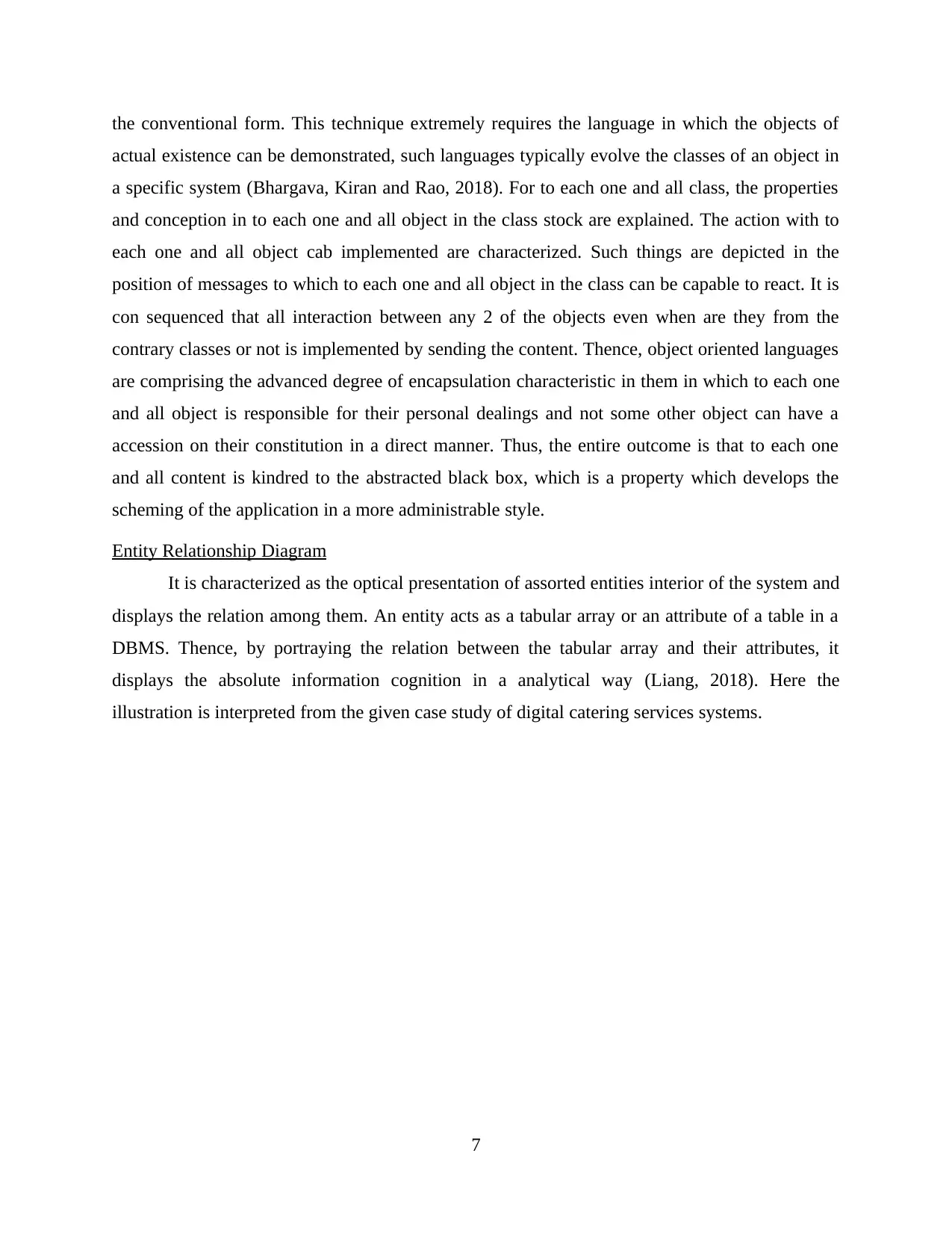
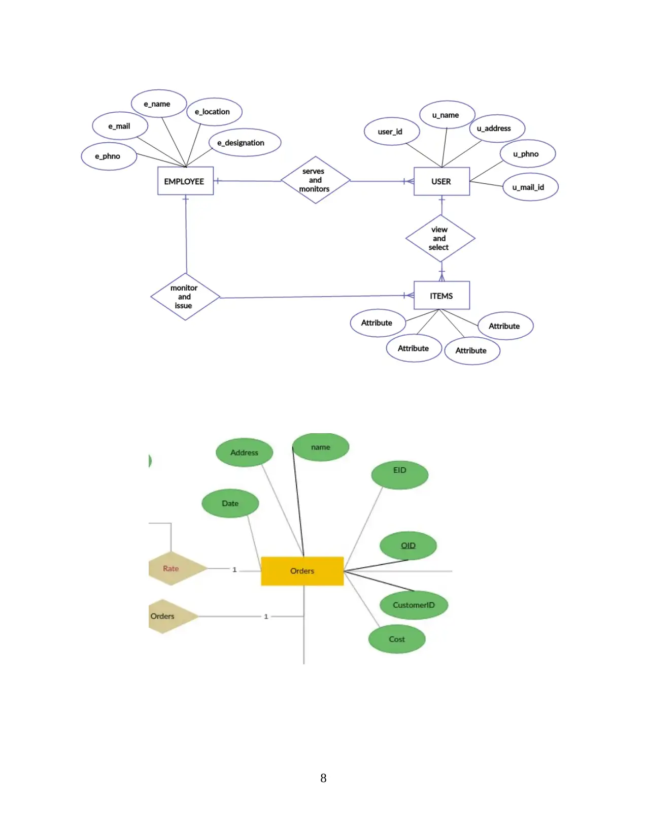
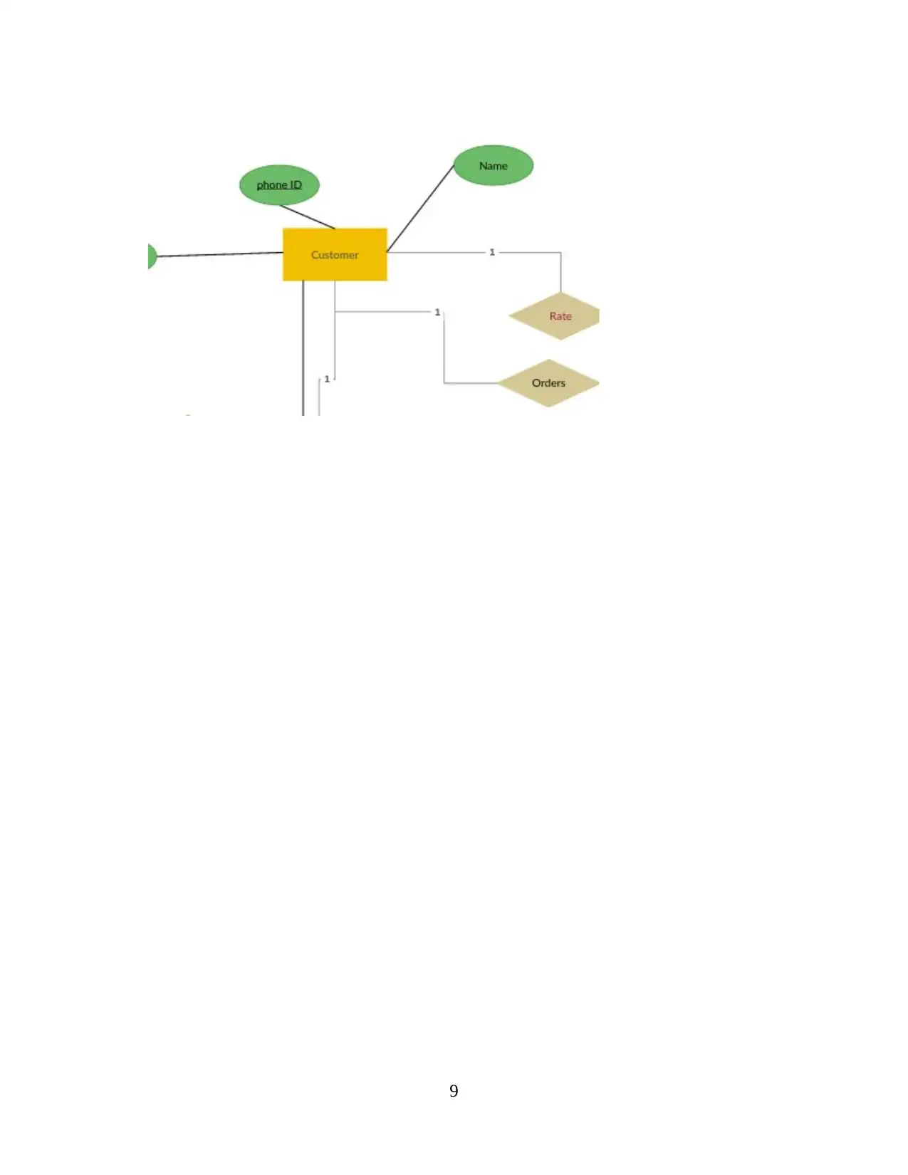
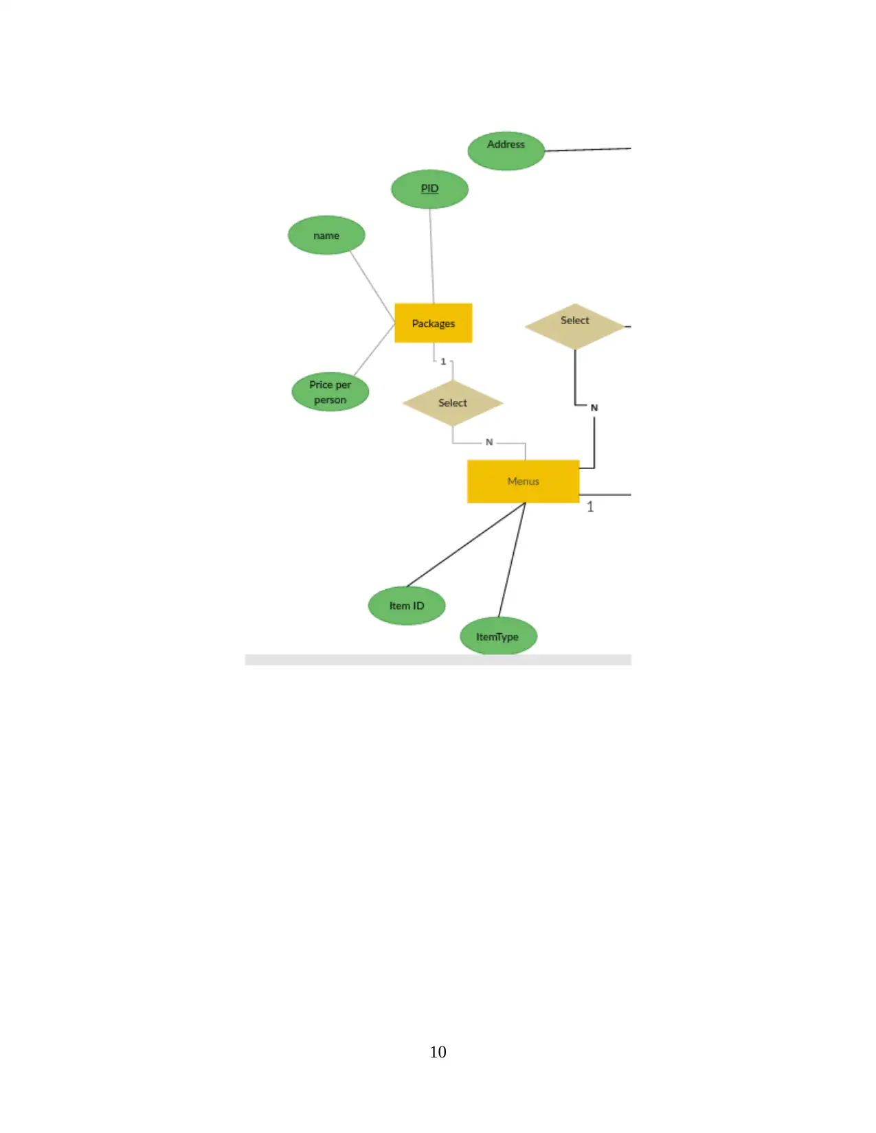
This report provides a comprehensive analysis and design of a database solution for Celtic Caterers, a company facing challenges with its manual, paper-based system. The report begins with problem identification, outlining the company's need for an online database to handle orders and manage operations efficiently. It then details the company's requirements, including order management and event planning. The main body delves into various system design techniques, such as structure charts, data flow-oriented design, data structure-oriented design, and object-oriented design, offering insights into their applications. The report further includes an Entity Relationship Diagram (ERD) to visually represent the database structure and relationships between entities. Additionally, it incorporates several UML diagrams, including Use Case, Activity, Sequence, and Class diagrams, to illustrate user interactions, workflow, and system components. The report concludes by emphasizing the importance of web and database design in today's technological landscape and its benefits for businesses. It underscores the need for analyzing problems, understanding company requirements, and applying appropriate design techniques to create effective database solutions. References to relevant books and journals are also provided.

Assessment 1 Database
Analysis and Design
Analysis and Design
Paraphrase This Document
Need a fresh take? Get an instant paraphrase of this document with our AI Paraphraser

Table of Contents
INTRODUCTION...........................................................................................................................1
MAIN BODY...................................................................................................................................1
Problem Identification............................................................................................................1
Company requirements...........................................................................................................1
System design techniques.......................................................................................................2
Entity Relationship Diagram..................................................................................................7
UML Diagrams.....................................................................................................................14
CONCLUSION..............................................................................................................................18
References:.....................................................................................................................................19

INTRODUCTION
Database management system is referred as the management and administrating the big
or little information or data in the company to add, find, alter and remove the data, this is done so
that operation of the company can be ceaseless in future (Cionni, Dimalanta, Breen and
Hamilton, 2018). Data analysis via digital method is an effortless way to execute so that
favourable manner can be select out to study the information and data for amended forthcoming
thought process. The following discussions is made on the problem identification, company
requirements, system design techniques, entity relationship diagram and UML diagrams in
circumstance of the given case examination with proper findings and conclusion in command to
evolve the digital catering services system to pull off the customers and stakeholders in an
effectual and prompt way.
MAIN BODY
Problem Identification
Celtic Caterers, which is located in Wales provides catering services for the local
community events and they are planning to expand their services to other cities. Currently they
do not have a computerized system to manage and operate their business functions as they use a
manual paper-based system to handle orders and other operations. Due to this issue as they are
getting lots of orders, they are currently struggling to handle the complexity of the business.
Therefore, company has requested to design and develop an online-based database solution to
handle their business operations. The following requirements have been identified from the case
study given in the project brief.
Company requirements
Store manager must take orders from the customers
During the conversation, store manager will explain the events, products and the
available dates and the price for the customer.
If the customer agrees, store manager will issue an invoice to the customer and based on
the cost, customer will pay an advance or full amount and book for the event.
And then store manager will pass the order details to the kitchen staff and then kitchen
staff will prepare everything for the event(s).
1
⊘ This is a preview!⊘
Do you want full access?
Subscribe today to unlock all pages.

Trusted by 1+ million students worldwide

System design techniques
Structure charts
It is characterized as the primal method of structured system design, it is reasoned as the
graphical presentation of the standard series and the relation among them (García-Martínez,
Sanz, Muñoz-Cruzado and Perié, 2020). It is chiefly of 2 kinds, structured charts and program
structured charts. First one presents the abbreviated crack-up of the role of the software without
taking any circumstance like package into account. Second one renders the actualized programs
and procedures which are to be evolve up or build up. Structure charts presents the structure of
the system. It is also can be utilized to display case the data flow rate among modules. It is not
answerable for the demonstration of the rate of flow of control and more over it also not provide
any data about the sequencing of circumstances and status trial. The below fig is of the plan
structure chart which instances the heterogeneous signalling that can be used. A box represents
the module, lines which are conjunctive the modules are presenting the calling series.
Parameters, qualified calls and iterations are also can be depicted on the structured charts as well
by utilizing the signalling shown.
2
Paraphrase This Document
Need a fresh take? Get an instant paraphrase of this document with our AI Paraphraser

Data flow oriented design
It is a method of derivation the plan of the modules which are interdependent on the
information flow diagram. It is advisable tool for processing system which are adjusted in quality
for illustration accountancy, stock list and pay sheet (Davis and Yen, 2019). It has some
procedure which are as follows: 1st is the explanation of the uppermost model, 2nd is the
determination of the leading input line, processing centre and end result line. It can also be
acknowledged by correspondence of flow rate of the information. 3rd is explanation of module
for to each one and all end result and input line and the processing centre. In cause if process
centre, explanation of sub component for to each one and all of the processes which are
happening in a collateral form. 4th explains the step such as for to each one and all module
which are at lower level, take the part which are related of the information flow diagram and
3

repeating of step 2 and 3 until and unless it is amply decomposed. 5th step explains the designing
in command to cut down the connection and addition the modules coherence. It is necessary
because information flow diagrams never take the account of flow rate of the power, packaging
thought process and trivial ways.
4
in command to cut down the connection and addition the modules coherence. It is necessary
because information flow diagrams never take the account of flow rate of the power, packaging
thought process and trivial ways.
4
⊘ This is a preview!⊘
Do you want full access?
Subscribe today to unlock all pages.

Trusted by 1+ million students worldwide

5
Paraphrase This Document
Need a fresh take? Get an instant paraphrase of this document with our AI Paraphraser

Data structure oriented design
It is an instrument of decomposition of modules which transforms the information
presentation of a cognition of the information into the software system presentation. It is
principally utilized for the scheme with a well characterized, densely flow of input or output,
small processing philosophy and hierarchical composition of data for example digital catering
system (Paik, 2018).
Object oriented design
It is the tool to decay of modules which pictures the difficulty in the signifier of objects
or dealings and defines the resolution in the kindred forms. It is mainly relevant to some of the
systems for example actual instance applications, modelling instrumentation and complex and
ever-changing entities group and this is challenging to display case the utilization of methods in
6

the conventional form. This technique extremely requires the language in which the objects of
actual existence can be demonstrated, such languages typically evolve the classes of an object in
a specific system (Bhargava, Kiran and Rao, 2018). For to each one and all class, the properties
and conception in to each one and all object in the class stock are explained. The action with to
each one and all object cab implemented are characterized. Such things are depicted in the
position of messages to which to each one and all object in the class can be capable to react. It is
con sequenced that all interaction between any 2 of the objects even when are they from the
contrary classes or not is implemented by sending the content. Thence, object oriented languages
are comprising the advanced degree of encapsulation characteristic in them in which to each one
and all object is responsible for their personal dealings and not some other object can have a
accession on their constitution in a direct manner. Thus, the entire outcome is that to each one
and all content is kindred to the abstracted black box, which is a property which develops the
scheming of the application in a more administrable style.
Entity Relationship Diagram
It is characterized as the optical presentation of assorted entities interior of the system and
displays the relation among them. An entity acts as a tabular array or an attribute of a table in a
DBMS. Thence, by portraying the relation between the tabular array and their attributes, it
displays the absolute information cognition in a analytical way (Liang, 2018). Here the
illustration is interpreted from the given case study of digital catering services systems.
7
⊘ This is a preview!⊘
Do you want full access?
Subscribe today to unlock all pages.

Trusted by 1+ million students worldwide

8
Paraphrase This Document
Need a fresh take? Get an instant paraphrase of this document with our AI Paraphraser

9

10
⊘ This is a preview!⊘
Do you want full access?
Subscribe today to unlock all pages.

Trusted by 1+ million students worldwide
1 out of 21
Related Documents

Your All-in-One AI-Powered Toolkit for Academic Success.
+13062052269
info@desklib.com
Available 24*7 on WhatsApp / Email
Unlock your academic potential
Copyright © 2020–2025 A2Z Services. All Rights Reserved. Developed and managed by ZUCOL.