Report on Systems Analysis and Information Systems: Event Management
VerifiedAdded on  2019/10/18
|19
|1321
|314
Report
AI Summary
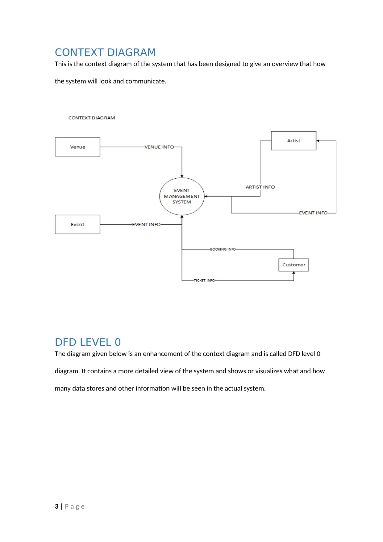
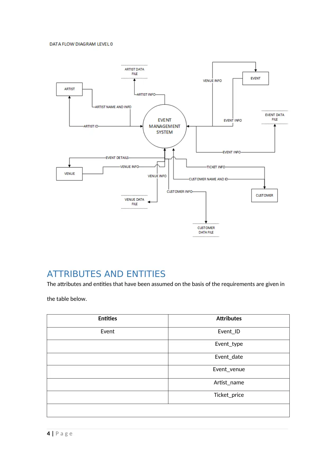
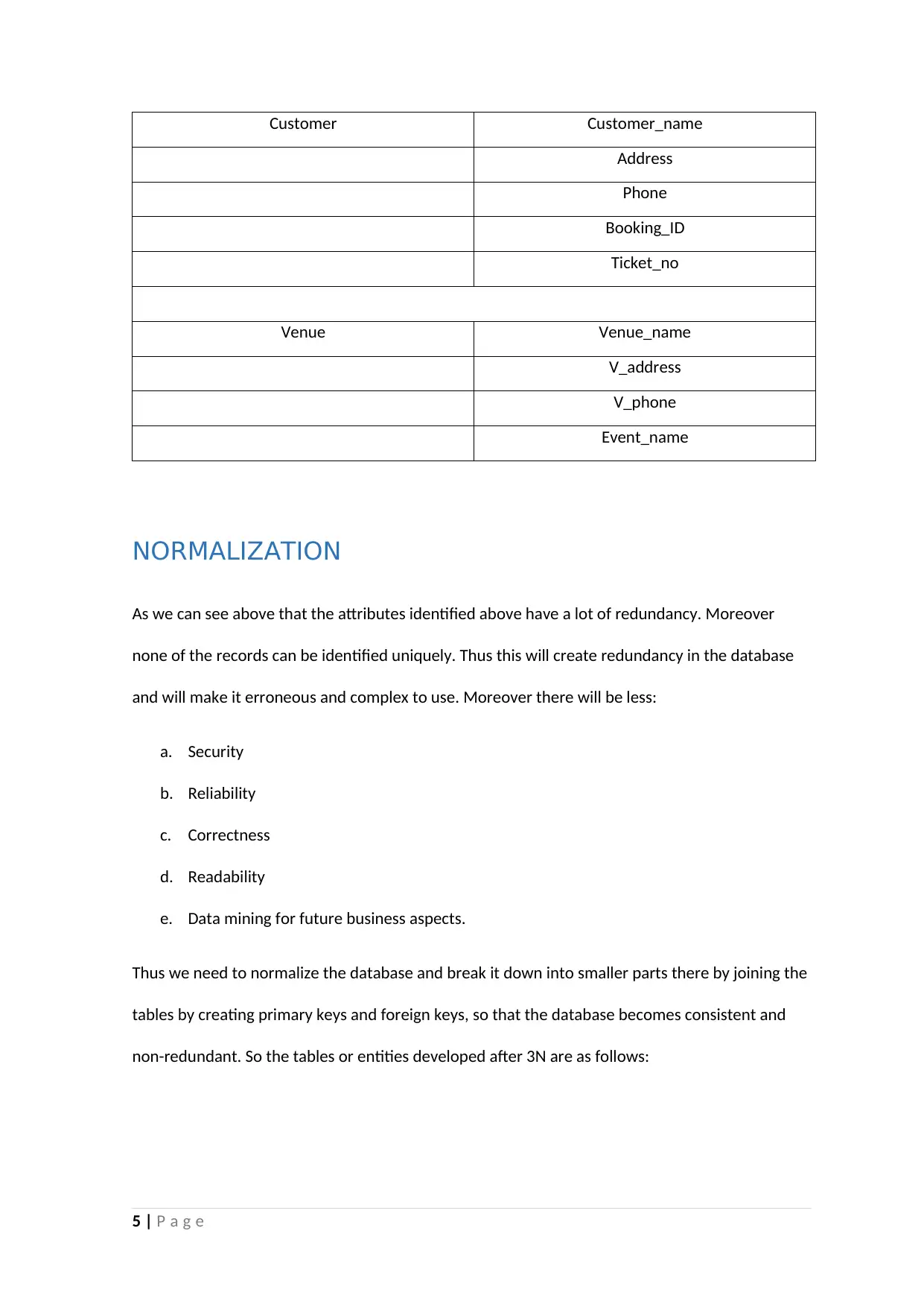
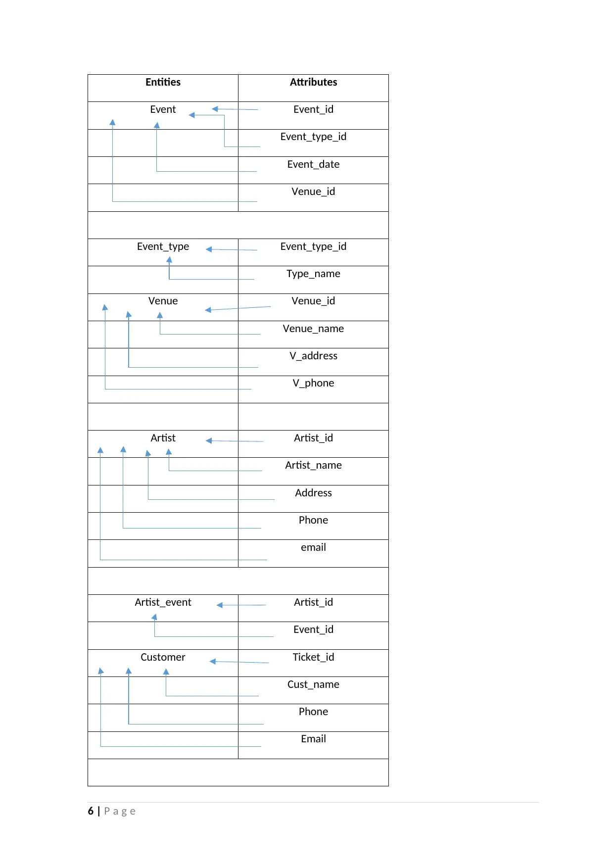
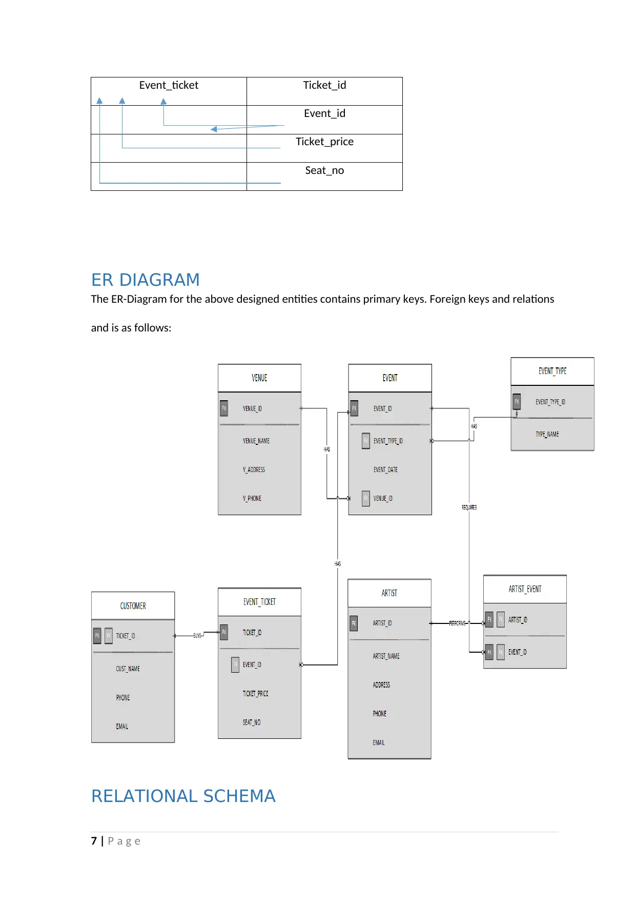
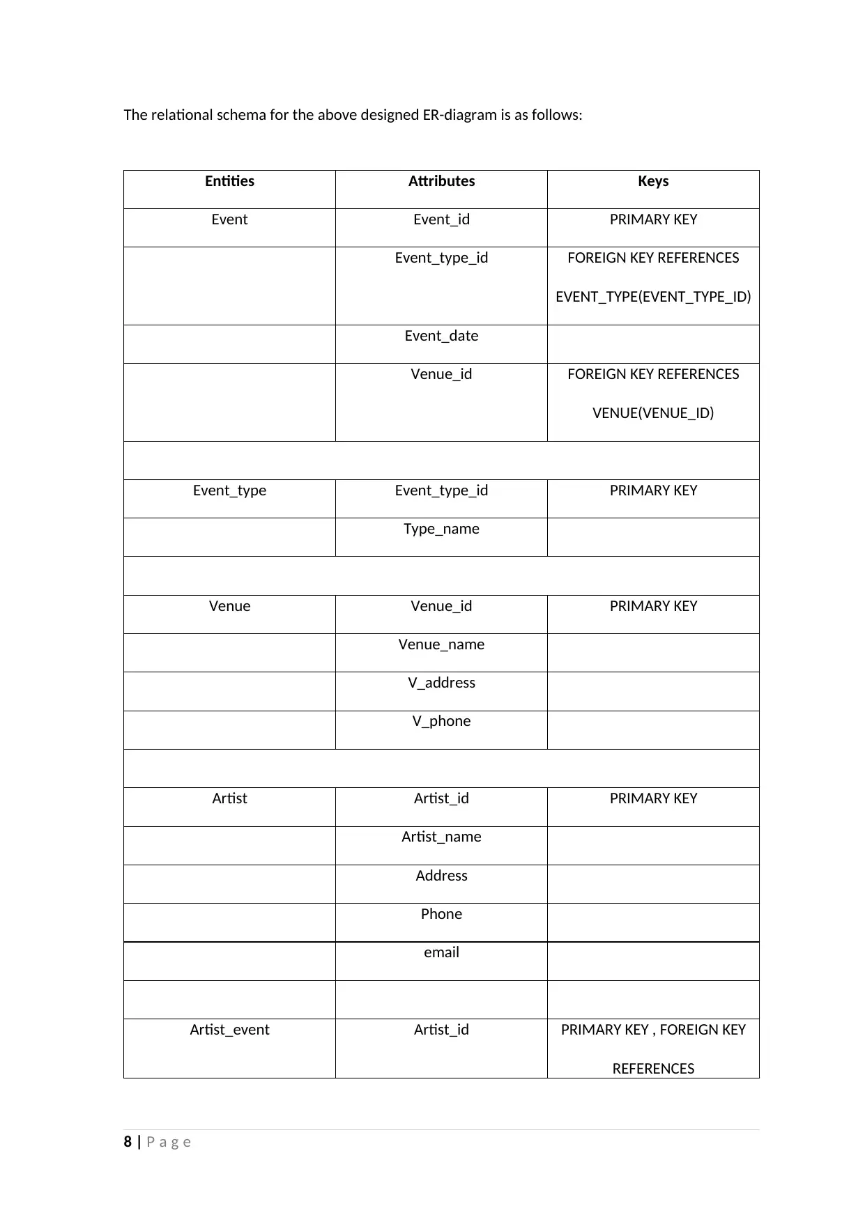
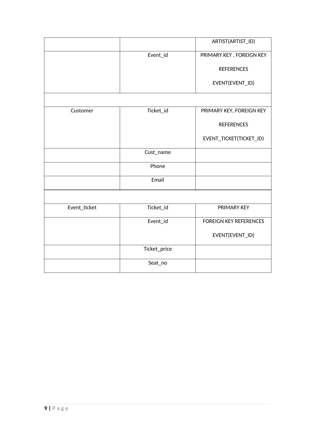
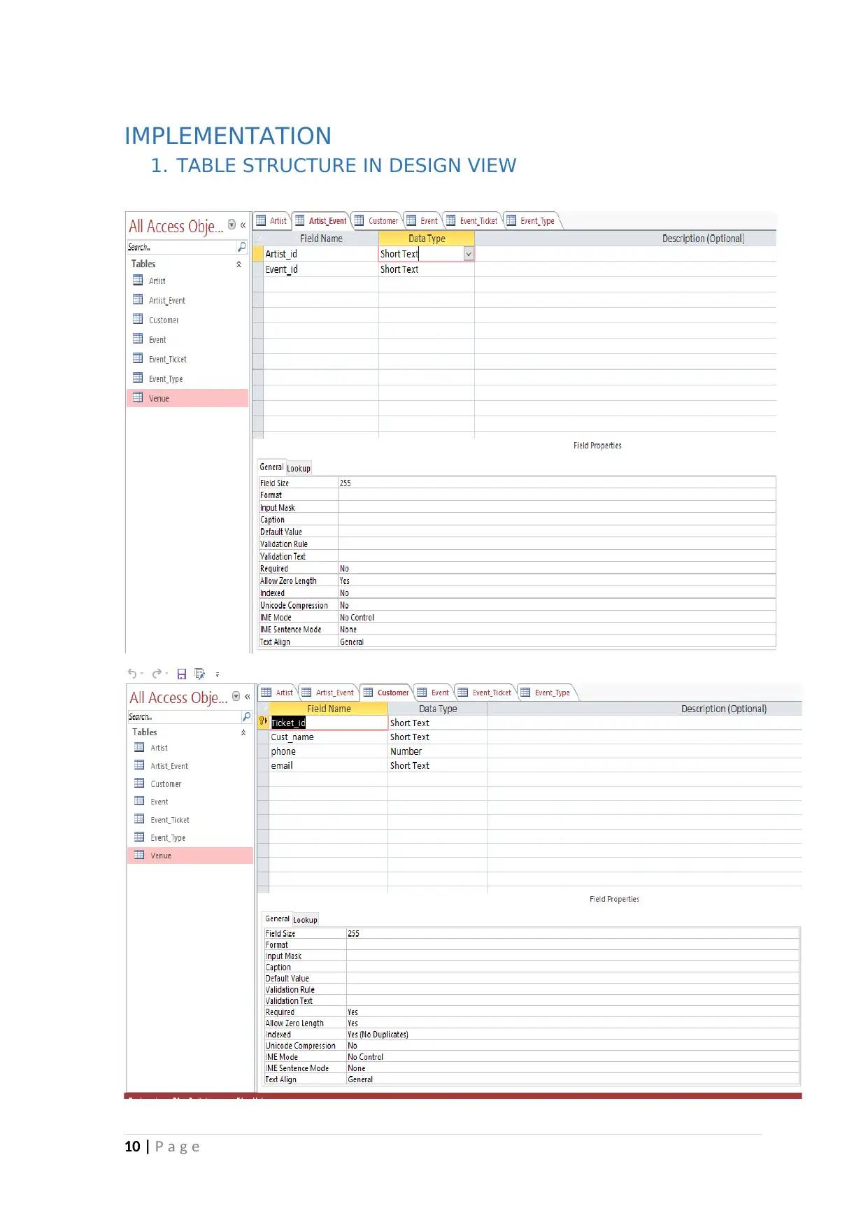
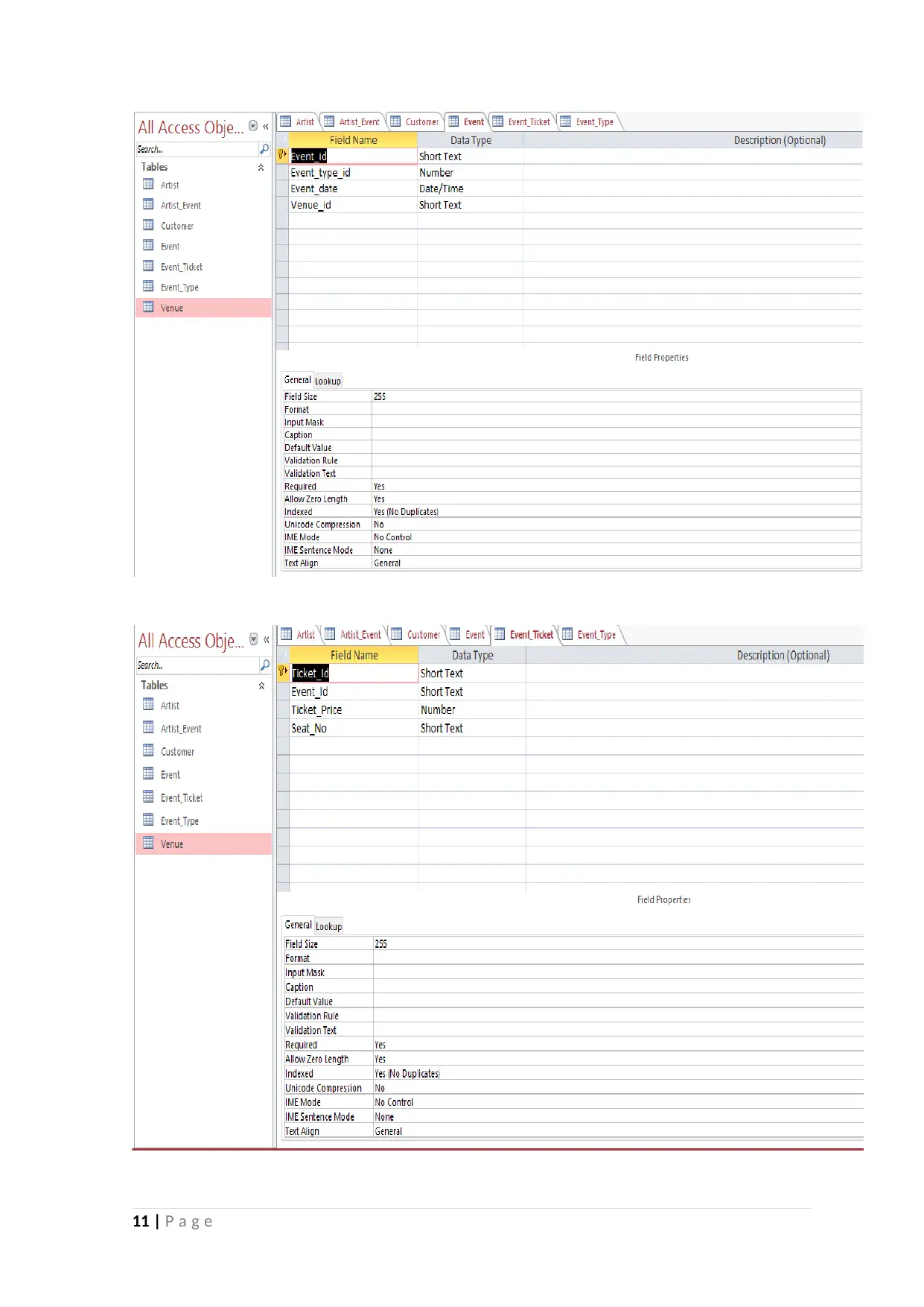
This report presents the design and implementation of an event management system database. It begins with an introduction outlining the system's purpose: to manage information related to venues, artists, ticket bookings, and events. The report includes visual designs like context diagrams and DFD level 0 diagrams to illustrate the system's overview and data flow. The report also details the entities and attributes, followed by a normalization process to reduce redundancy and improve data integrity. An ER diagram and relational schema are provided to visualize the database structure. The implementation section covers table structures, relationships, SQL queries for ticket and event type queries, and report generation. The report also suggests several improvements, including security features, detailed customer and event information, and the use of cloud databases for backups. The conclusion emphasizes the importance of incorporating these improvements for future scalability and data mining. References used for completing the assignment are also provided.

Introduction to Systems Analysis and Information Systems
REPORT
AUGUST 15, 2016
STUDENT
REPORT
AUGUST 15, 2016
STUDENT
Paraphrase This Document
Need a fresh take? Get an instant paraphrase of this document with our AI Paraphraser

Contents
INTRODUCTION.................................................................................................................................2
CONTEXT DIAGRAM..........................................................................................................................2
DFD LEVEL 0......................................................................................................................................2
ATTRIBUTES AND ENTITIES...............................................................................................................2
NORMALIZATION..............................................................................................................................2
ER DIAGRAM.....................................................................................................................................2
RELATIONAL SCHEMA.......................................................................................................................2
IMPLEMENTATION............................................................................................................................2
1. TABLE STRUCTURE IN DESIGN VIEW.....................................................................................2
2. RELATIONSHIPS.....................................................................................................................2
3. QUERY IN DESIGN VIEW........................................................................................................2
4. SAMPLE DATA IN FORMS AND REPORTS...............................................................................2
5. SAMPLES OF OUTPUT FROM THE SYSTEM (TICKETS, QUERIES AND REPORTS).....................2
IMPROVEMENTS...............................................................................................................................2
CONCLUSION....................................................................................................................................2
REFERENCES......................................................................................................................................2
1 | P a g e

INTRODUCTION
The report is about an event management system that will be designed to hold the information
of:
A. Venues
B. Artists
C. Ticket bookings
D. Events
As given in the requirements that the events or performances will include different types of
events and artist. Typical types of event are concerts, variety shows, comedy shows etc. For
a concert, the artist will be the band name; for a comedy show the comedian/comedienne;
for a variety show the leading name will appear. Thus after analysis of the given
requirements, there came up certain hidden requirements or we can say non-functional
requirements and functional as well. So apart from the stated requirements, the information
related to other aspects like address, date, who will perform where, who booked which ticket
and other general information will also be stored in the database. Thus the document below
contains visual designs and database references that have been designed to meet the user
requirements and build it into an actual product. Along with this some enhancements have
also been suggested for future expansion and improvements because with the time, the size
and complexity of the database will also increase. So to keep the system updated with the
technological changes and changing user requirements, the improvements should always
take place.
2 | P a g e
⊘ This is a preview!⊘
Do you want full access?
Subscribe today to unlock all pages.

Trusted by 1+ million students worldwide

CONTEXT DIAGRAM
This is the context diagram of the system that has been designed to give an overview that how
the system will look and communicate.
DFD LEVEL 0
The diagram given below is an enhancement of the context diagram and is called DFD level 0
diagram. It contains a more detailed view of the system and shows or visualizes what and how
many data stores and other information will be seen in the actual system.
3 | P a g e
Paraphrase This Document
Need a fresh take? Get an instant paraphrase of this document with our AI Paraphraser

ATTRIBUTES AND ENTITIES
The attributes and entities that have been assumed on the basis of the requirements are given in
the table below.
Entities Attributes
Event Event_ID
Event_type
Event_date
Event_venue
Artist_name
Ticket_price
4 | P a g e
The attributes and entities that have been assumed on the basis of the requirements are given in
the table below.
Entities Attributes
Event Event_ID
Event_type
Event_date
Event_venue
Artist_name
Ticket_price
4 | P a g e

Customer Customer_name
Address
Phone
Booking_ID
Ticket_no
Venue Venue_name
V_address
V_phone
Event_name
NORMALIZATION
As we can see above that the attributes identified above have a lot of redundancy. Moreover
none of the records can be identified uniquely. Thus this will create redundancy in the database
and will make it erroneous and complex to use. Moreover there will be less:
a. Security
b. Reliability
c. Correctness
d. Readability
e. Data mining for future business aspects.
Thus we need to normalize the database and break it down into smaller parts there by joining the
tables by creating primary keys and foreign keys, so that the database becomes consistent and
non-redundant. So the tables or entities developed after 3N are as follows:
5 | P a g e
⊘ This is a preview!⊘
Do you want full access?
Subscribe today to unlock all pages.

Trusted by 1+ million students worldwide

Entities Attributes
Event Event_id
Event_type_id
Event_date
Venue_id
Event_type Event_type_id
Type_name
Venue Venue_id
Venue_name
V_address
V_phone
Artist Artist_id
Artist_name
Address
Phone
email
Artist_event Artist_id
Event_id
Customer Ticket_id
Cust_name
Phone
Email
6 | P a g e
Event Event_id
Event_type_id
Event_date
Venue_id
Event_type Event_type_id
Type_name
Venue Venue_id
Venue_name
V_address
V_phone
Artist Artist_id
Artist_name
Address
Phone
Artist_event Artist_id
Event_id
Customer Ticket_id
Cust_name
Phone
6 | P a g e
Paraphrase This Document
Need a fresh take? Get an instant paraphrase of this document with our AI Paraphraser

Event_ticket Ticket_id
Event_id
Ticket_price
Seat_no
ER DIAGRAM
The ER-Diagram for the above designed entities contains primary keys. Foreign keys and relations
and is as follows:
RELATIONAL SCHEMA
7 | P a g e
Event_id
Ticket_price
Seat_no
ER DIAGRAM
The ER-Diagram for the above designed entities contains primary keys. Foreign keys and relations
and is as follows:
RELATIONAL SCHEMA
7 | P a g e

The relational schema for the above designed ER-diagram is as follows:
Entities Attributes Keys
Event Event_id PRIMARY KEY
Event_type_id FOREIGN KEY REFERENCES
EVENT_TYPE(EVENT_TYPE_ID)
Event_date
Venue_id FOREIGN KEY REFERENCES
VENUE(VENUE_ID)
Event_type Event_type_id PRIMARY KEY
Type_name
Venue Venue_id PRIMARY KEY
Venue_name
V_address
V_phone
Artist Artist_id PRIMARY KEY
Artist_name
Address
Phone
email
Artist_event Artist_id PRIMARY KEY , FOREIGN KEY
REFERENCES
8 | P a g e
Entities Attributes Keys
Event Event_id PRIMARY KEY
Event_type_id FOREIGN KEY REFERENCES
EVENT_TYPE(EVENT_TYPE_ID)
Event_date
Venue_id FOREIGN KEY REFERENCES
VENUE(VENUE_ID)
Event_type Event_type_id PRIMARY KEY
Type_name
Venue Venue_id PRIMARY KEY
Venue_name
V_address
V_phone
Artist Artist_id PRIMARY KEY
Artist_name
Address
Phone
Artist_event Artist_id PRIMARY KEY , FOREIGN KEY
REFERENCES
8 | P a g e
⊘ This is a preview!⊘
Do you want full access?
Subscribe today to unlock all pages.

Trusted by 1+ million students worldwide

ARTIST(ARTIST_ID)
Event_id PRIMARY KEY , FOREIGN KEY
REFERENCES
EVENT(EVENT_ID)
Customer Ticket_id PRIMARY KEY, FOREIGN KEY
REFERENCES
EVENT_TICKET(TICKET_ID)
Cust_name
Phone
Email
Event_ticket Ticket_id PRIMARY KEY
Event_id FOREIGN KEY REFERENCES
EVENT(EVENT_ID)
Ticket_price
Seat_no
9 | P a g e
Event_id PRIMARY KEY , FOREIGN KEY
REFERENCES
EVENT(EVENT_ID)
Customer Ticket_id PRIMARY KEY, FOREIGN KEY
REFERENCES
EVENT_TICKET(TICKET_ID)
Cust_name
Phone
Event_ticket Ticket_id PRIMARY KEY
Event_id FOREIGN KEY REFERENCES
EVENT(EVENT_ID)
Ticket_price
Seat_no
9 | P a g e
Paraphrase This Document
Need a fresh take? Get an instant paraphrase of this document with our AI Paraphraser

IMPLEMENTATION
1. TABLE STRUCTURE IN DESIGN VIEW
10 | P a g e
1. TABLE STRUCTURE IN DESIGN VIEW
10 | P a g e

11 | P a g e
⊘ This is a preview!⊘
Do you want full access?
Subscribe today to unlock all pages.

Trusted by 1+ million students worldwide
1 out of 19
Related Documents

Your All-in-One AI-Powered Toolkit for Academic Success.
 +13062052269
info@desklib.com
Available 24*7 on WhatsApp / Email
Unlock your academic potential
Copyright © 2020–2025 A2Z Services. All Rights Reserved. Developed and managed by ZUCOL.