Database Design and Analysis Report for Emergency Room Case Study

Verified

Added on  2023/01/19

|10
|1594
|96
Report
AI Summary
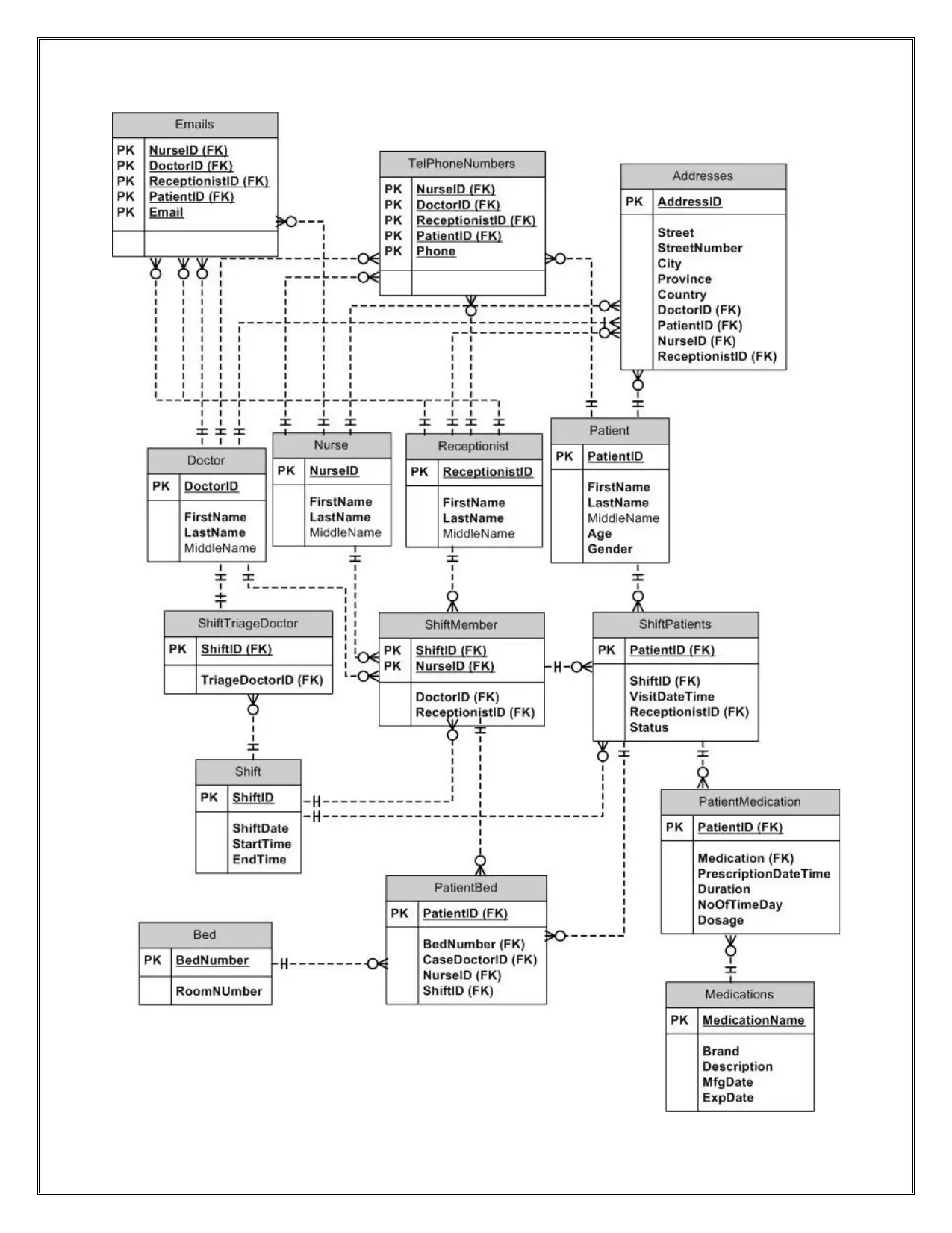
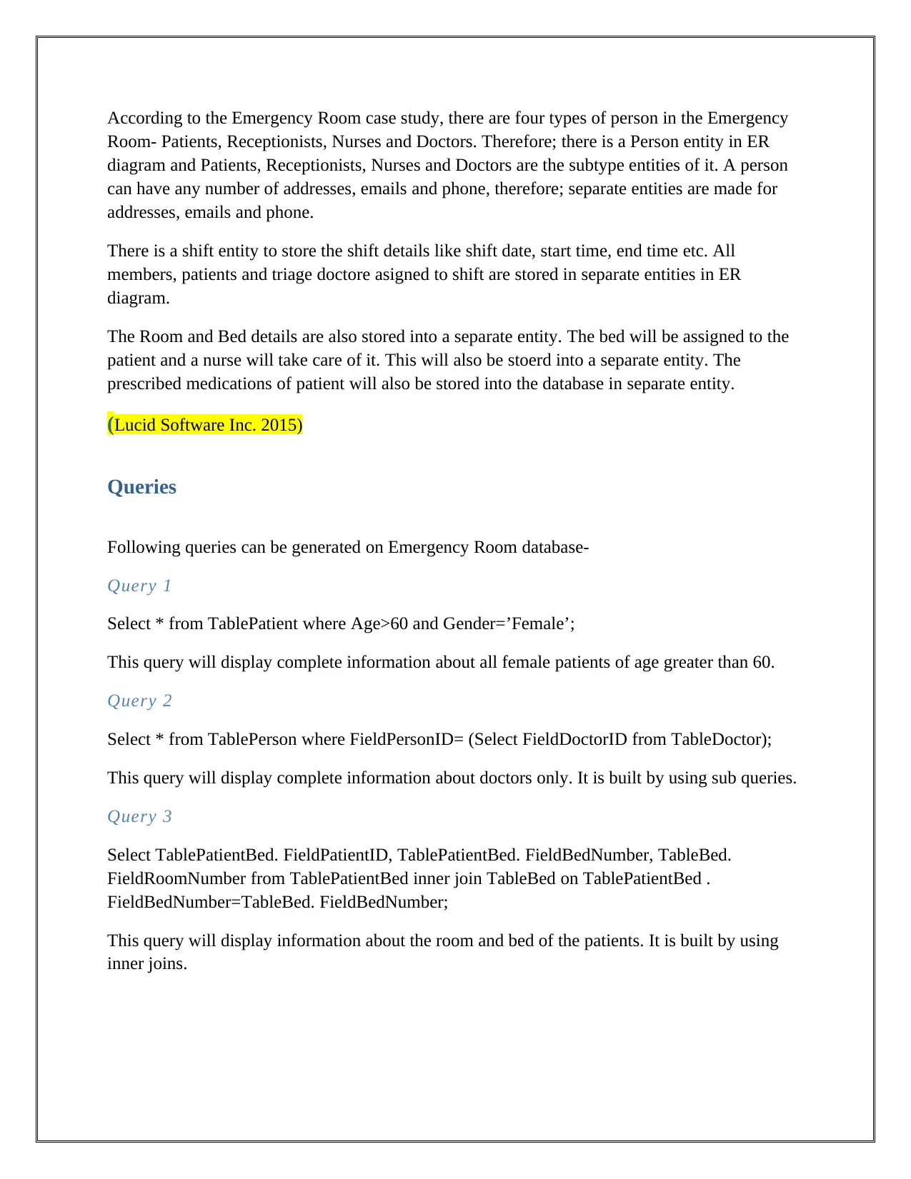
This report presents a database design for an emergency room, covering various aspects of database management. It begins with an overview of the ER diagram, illustrating the entities such as patients, doctors, nurses, and other related entities, along with their attributes and relationships, including the handling of many-to-many relationships. The report also details several SQL queries designed to retrieve specific information from the database, such as patient details, doctor information, and medication details. Furthermore, the report discusses the principles of entity-relationship modeling, database normalization (1NF, 2NF, and 3NF), and functional dependencies. It contrasts logical and physical database design, highlighting the roles of database management systems (DBMS) like MySQL. The report also explores top-down and bottom-up design approaches, suggesting the suitability of the bottom-up method for the emergency room scenario. Finally, it addresses potential issues in an emergency room database, including ethical, privacy, security, and organizational concerns, and provides references to support the information presented.
Document Page
Database Design
April 16
2019
Student ID:
Student Name:
Module Tutor:
tabler-icon-diamond-filled.svg

Paraphrase This Document

Need a fresh take? Get an instant paraphrase of this document with our AI Paraphraser
Document Page
Report
Contents
Report..........................................................................................................................................................2
ER Diagram.................................................................................................................................................3
Queries........................................................................................................................................................5
Reflection Letter..........................................................................................................................................6
Entity Relationship Modeling..................................................................................................................6
Logical vs Physical Database Design......................................................................................................8
Database Management System................................................................................................................9
Top-Down vs Bottom-Up Design............................................................................................................9
Issues Occurred in the Emergency Room................................................................................................9
References.................................................................................................................................................11
ER Diagram
Document Page
Document Page
According to the Emergency Room case study, there are four types of person in the Emergency
Room- Patients, Receptionists, Nurses and Doctors. Therefore; there is a Person entity in ER
diagram and Patients, Receptionists, Nurses and Doctors are the subtype entities of it. A person
can have any number of addresses, emails and phone, therefore; separate entities are made for
addresses, emails and phone.
There is a shift entity to store the shift details like shift date, start time, end time etc. All
members, patients and triage doctore asigned to shift are stored in separate entities in ER
diagram.
The Room and Bed details are also stored into a separate entity. The bed will be assigned to the
patient and a nurse will take care of it. This will also be stoerd into a separate entity. The
prescribed medications of patient will also be stored into the database in separate entity.
(Lucid Software Inc. 2015)
Queries
Following queries can be generated on Emergency Room database-
Query 1
Select * from TablePatient where Age>60 and Gender=’Female’;
This query will display complete information about all female patients of age greater than 60.
Query 2
Select * from TablePerson where FieldPersonID= (Select FieldDoctorID from TableDoctor);
This query will display complete information about doctors only. It is built by using sub queries.
Query 3
Select TablePatientBed. FieldPatientID, TablePatientBed. FieldBedNumber, TableBed.
FieldRoomNumber from TablePatientBed inner join TableBed on TablePatientBed .
FieldBedNumber=TableBed. FieldBedNumber;
This query will display information about the room and bed of the patients. It is built by using
inner joins.
tabler-icon-diamond-filled.svg

Paraphrase This Document

Need a fresh take? Get an instant paraphrase of this document with our AI Paraphraser
Document Page
Query 4
Select FieldShiftID, FieldTriageDoctorID, FieldFirstName, FieldLastName from TableDoctor
inner join TableShiftTriageDoctor on TableDoctor. FieldDoctorID = TableShiftTriageDoctor.
FieldTriageDoctorID Inner join TablePerson on TablePerson. FieldPersonID= TableDoctor.
FieldDoctorID;
This query will display the triage doctor in shifts in the Emergency Room. It is built by using
inner joins.
Query 5
Select TablePatientMedication. FieldPatientID, TablePatientMedication. FieldMedication,
TableMedications. FieldBrand, TableMedications. FieldDescription from
TablePatientMedication inner join TableMedications on TablePatientMedication.
FieldMedication = TableMedications. FieldMedicationName;
This query will display the patients and their medications. It is built by using inner joins.
(Studytonight. 2014)
Reflection Letter
Entity Relationship Modeling
Entity Relationship Modeling shows the relationship between entities. Entities contain attributes
that show the properties of the entities e.g. the Person is an entity and personID, name etc. are the
attributes of entity Person.
There are different types of relationships in between the entities like 1-to-many, 1-to-1, many-to-
many. Many-to-many
In the Emergency Room’s ER diagram many-to-many relationships has been resolved because it
creates problem in database normalization. In normalized database, 1-to-1 and 1-to-many
relationships are used.
A person can have many addresses, many emails etc. that is why, there is 1-to-many relationship
in
Person and Addresses tables.
Document Page
The Emergency Room’s database is in third normal form. Firstly, the database is built into first
normal form, then second normal form and then third normal form. The normalized database is
achieved like below-
First Normal Form
To make database into first normal form following things are required-
- Remove repeated groups.
- Make separate tables.
First normal form removes the data redundancy from the database. Data redundancy means the
same data gets repeated in the database at more than one place.
Second Normal Form
To make database into second normal form following things are required-
- Set primary key in all new tables.
- Ensure all fields depend upon the primary key only.
Second normal form resolves the update anomalies. Update anomalies means somewhere the
data gets updated and somewhere the data does not get updated.
Third Normal Form
To make database into third normal form following things are required-
- Remove transitive dependency from all tables, if any.
Transitive dependency occurs when the attributes indirectly depend upon another attributes e.g.
X Y, YZ and XZ.
(teach-ict.com n.d.)
Functional Dependency in Tables
Shift Table
Shift (ShiftID, ShiftDate, StartTime, EndTime)
ShiftDate ShiftID
StartTime ShiftID
Document Page
EndTime ShiftID
ShiftID is the primary key and other fields are depending upon the Person ShiftID only.
All tables are following the same pattern and are in third normal form.
(Janalta Interactive Inc. 2015)
Entity Relationship Diagram Creation Steps
The Entity Relation Diagram is created by following steps-
- Generate entities which are required in the case study.
- Set attributes in each entity.
- Set primary key in each entity.
- Set relationships and cardinality in between the entities.
Logical vs Physical Database Design
Logical and Physical database design are both very important and required to present the system
to show the system requirements clearly. The difference between logical and physical database
design is as follows-
Logical Database Design
Logical database design is used to compile business requirements and represent that in the form
of model. It basically shows the requirement needs of the business.
After compiling the information reports and models are generated to clearly show the
requirements. Following diagrams are generally made in logical design-
- ER Diagram: The Entity Relationship Diagram is used to show categories of data and
relationship in between the data sets.
- Business Process Diagram: this diagram shows the activities of entities.
- Feedback Documentations
Physical Database Design
Physical database design creates the actual database based upon the business requirements
gathered in the logical database design. All gathered information is converted into relational
models and business models. The data in the relational models is stored in the form of tables.
For Emergency Room, the logical database is designed in the form of ER Diagram.
tabler-icon-diamond-filled.svg

Paraphrase This Document

Need a fresh take? Get an instant paraphrase of this document with our AI Paraphraser
Document Page
Database Management System
The database management system is the database system that gives the facility and all features to
create physical database and manage that later. There are different database management systems
e.g. MS Access, MYSQL, SQL Server, Oracle etc.
For the Emergency Room, we can use MYSQL. It gives options to create database and retrieve
data from the tables very easily and effectively.
Top-Down vs Bottom-Up Design
Software design is a process that conceptualizes the gathered business requirements. It designs
the system according to the gathered requirements. There are different approaches to make
system designs e.g. Top-Down and Bottom-Up.
Top-Down Approach
In Top-Down approach, the whole system is taken as one single entity and later decomposed into
sub systems according to achievements and requirements.
Bottom-Up Approach
In Bottom-Up approach, the different basic systems are taken and work together to form the
required system. The sub systems gathered until the required one system is not generated.
The Bottom-Up approach is best for the Emergency Room because we have very clear vision to
make the single system that will fulfill the gathered requirements in logical database design.
Issues Occurred in the Emergency Room
There are some issues that may occurred in the Emergency Room like below-
Ethical
There are some ethical issues that may occur in the Emergency Room like below-
- There should be proper care of patients.
- The discount in the fee of the patients should be given in special cases like old age etc.
Privacy
Document Page
There are some privacy issues that may occur in the Emergency Room like below-
- The privacy should be given to all persons within the Emergency Room e.g. Patients,
Doctors, Nurses etc.
- The data of any person should not be leaked.
Security
There are some security issues that may occur in the Emergency Room like below-
- The personal detail of all persons should be secured.
- The patient’s medical detail etc. should not be shared to anyone else by the Emergency
Room.
- There should be firewall etc. to secure the system data.
Organizational
There are some organizational issues that may occur in the Emergency Room like below-
- The organization should follow the all standards and norms before starting the business.
Document Page
References
Studytonight. (2014). Database Technology. [online] Available at:
http://www.studytonight.com/dbms/er-diagram.php. [Accessed 17 April 2019]
Lucid Software Inc. (2015). ER Diagram Symbols and Meaning. [online] Available at:
http://www.sparxsystems.com/enterprisearchitectuserguide/modelinglanguages/
dataflowdiagrams.html. [Accessed 17 April 2019]
Janalta Interactive Inc. (2015), Functional Dependency, [online] Available
at:http://www.techopedia.com/definition/19504/functional-dependency. [Accessed 17 April
2019]
teach-ict.com (n.d.), Third Normal Form, [online] Available
at:http://www.teach-ict.com/as_a2_ict_new/ocr/AS_G061/315_database_concepts/
normalisation/miniweb/pg9.htm. [Accessed 17 April 2019]
chevron_up_icon
1 out of 10
circle_padding
hide_on_mobile
zoom_out_icon
[object Object]