Database Design Project: Entities, Relationships, and SQL Queries
VerifiedAdded on 2021/01/02
|20
|1532
|227
Project
AI Summary
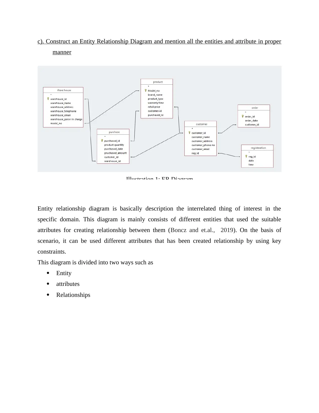
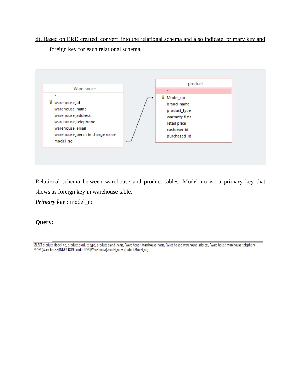
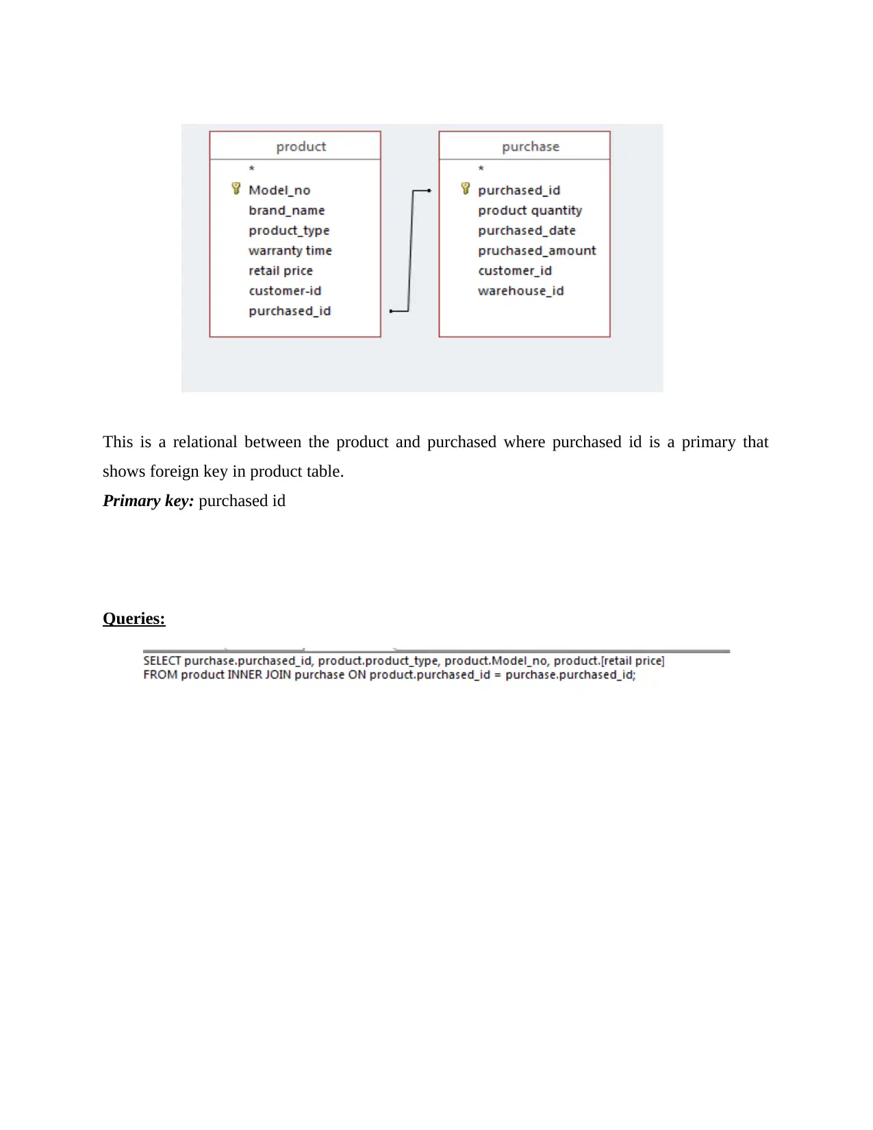
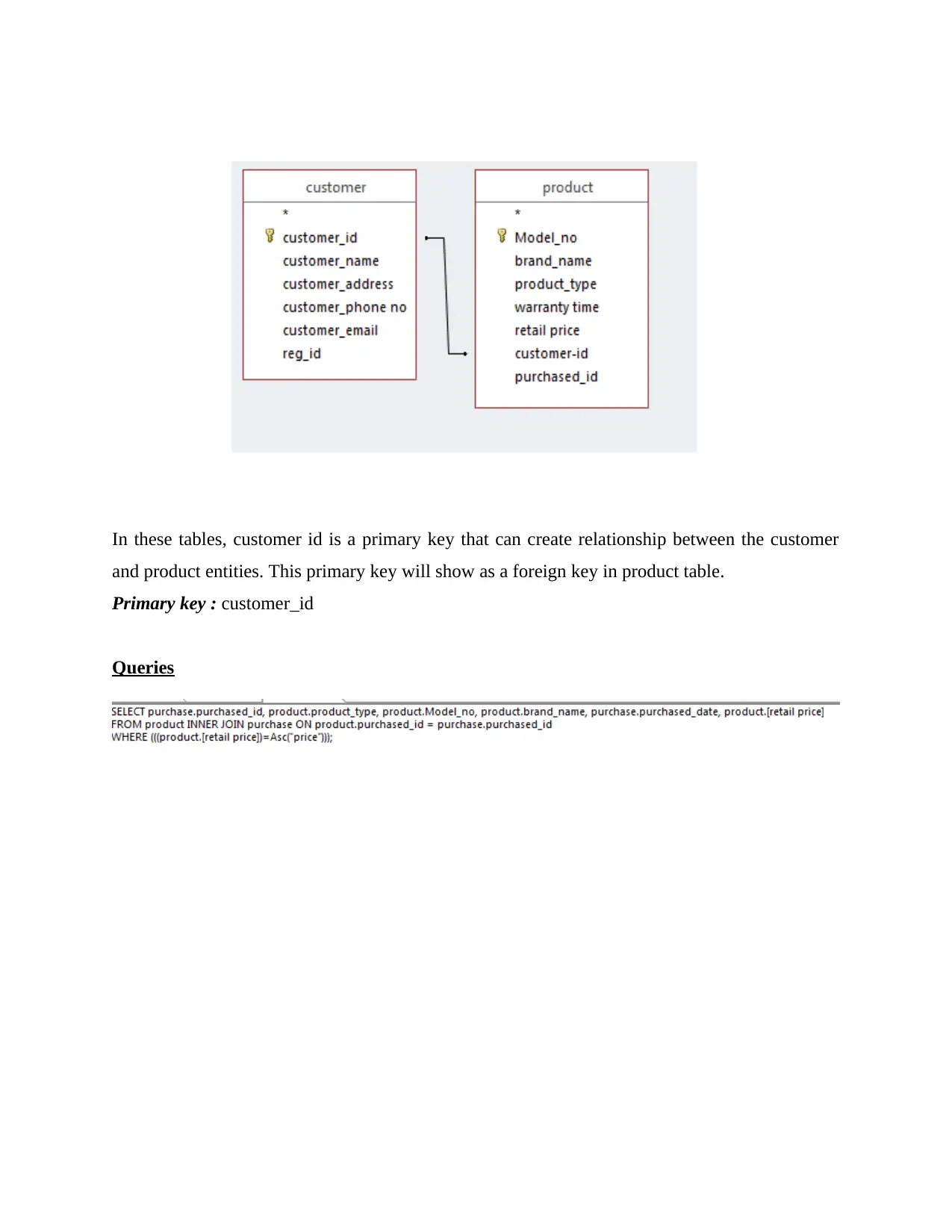
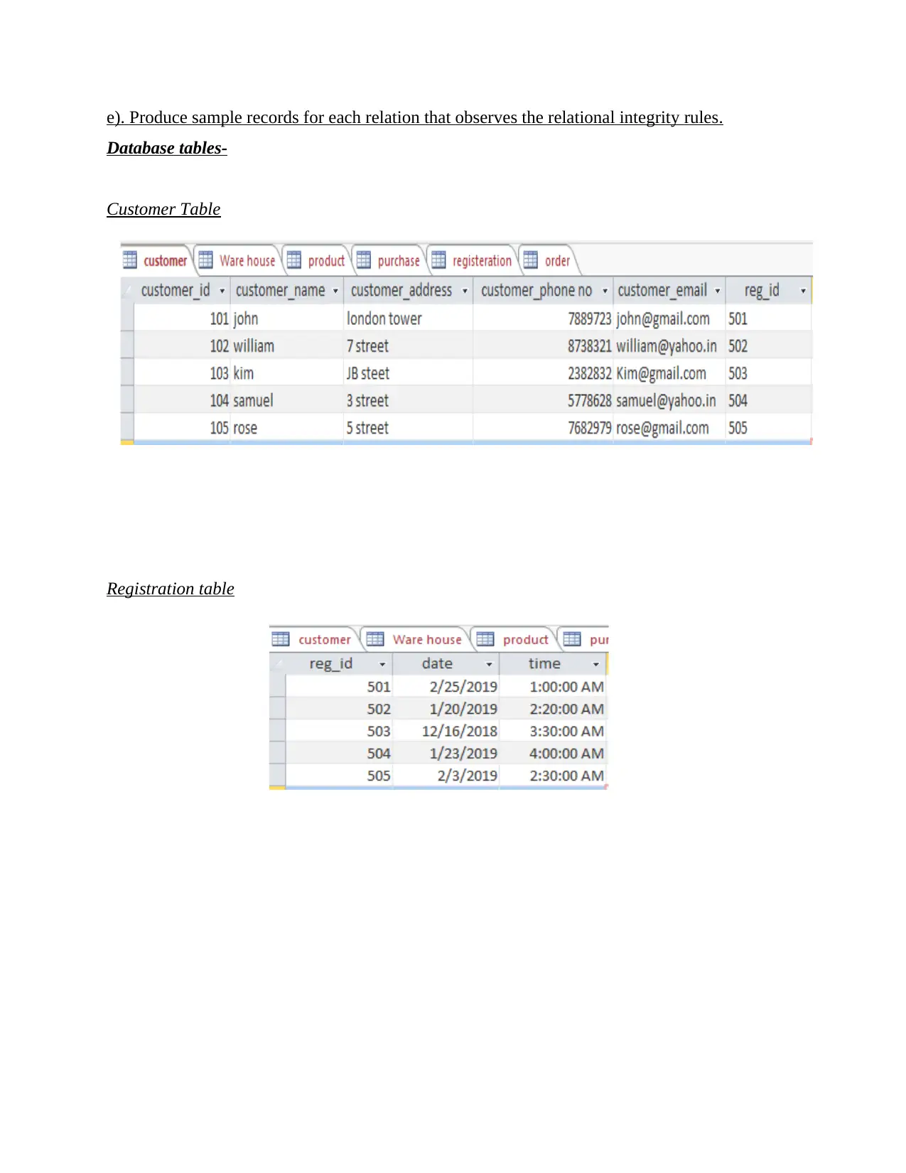
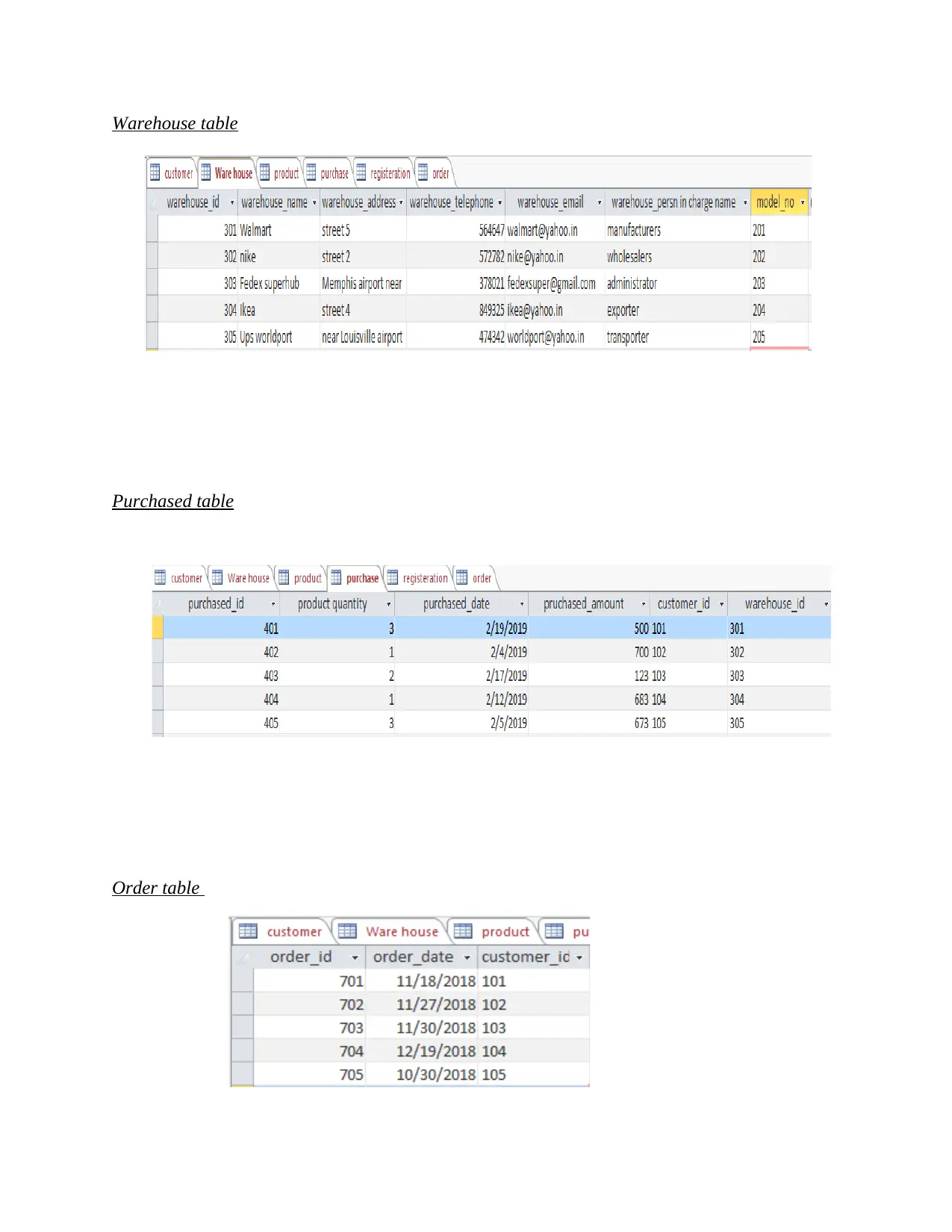
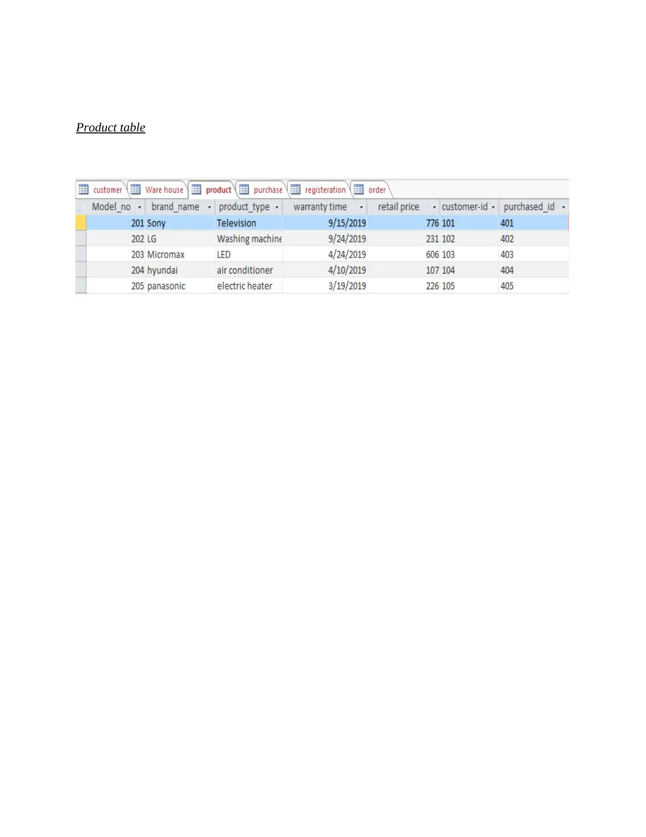
This assignment is a comprehensive database design project. It begins with identifying entities and their attributes, including primary keys, within a given scenario. The project then focuses on determining relationships between entities, specifying cardinality and participation constraints, and constructing an Entity Relationship Diagram (ERD). The ERD is subsequently converted into a relational schema, with clear indication of primary and foreign keys. Sample records are created for each relation, adhering to relational integrity rules. The project culminates in the generation of five SQL queries designed to manipulate data within the relations, with all query results provided. The assignment demonstrates a strong understanding of database design principles, including entity modeling, relationship mapping, schema creation, and SQL query implementation.

Database
Secure Best Marks with AI Grader
Need help grading? Try our AI Grader for instant feedback on your assignments.

Table of Contents
INTRODUCTION...........................................................................................................................3
TASKS.............................................................................................................................................3
a). Identify all the entities, complete all the entities with suitable attributes together with
assigned primary key...................................................................................................................3
b). Determine Cardinality, and participation for each related entity, relationships....................4
Relationship :..............................................................................................................................4
c). Construct an Entity Relationship Diagram and mention all the entities and attribute in
proper manner.............................................................................................................................6
d). Based on ERD created convert into the relational schema and also indicate primary key
and foreign key for each relational schema.................................................................................7
e). Produce sample records for each relation that observes the relational integrity rules.........10
f). Produce FIVE SQL queries that can be used to manipulate the data from each relation and
show ALL the results from each of the queries........................................................................13
CONCLUSION..............................................................................................................................16
REFERENCES..............................................................................................................................17

INTRODUCTION
Database management system is basically the collection of data that update, retrieve and
delete or manipulate the information in proper manner. DBMS is a type of software that provide
an interface to database for information retrieval or storage (Truyen and et.al., 2018). This report
will discuss about the entity relationship diagram and find out the specific entities with suitable
attribute. Furthermore, this assignment will describe the ER diagram that convert into the
relational schema. Produce the sample record of each relationship to observe the relational
integrity rules. At last, it will discuss about the SQL queries that can be used to manipulate the
data from each the relation and also shows the results from each queries.
TASKS
a). Identify all the entities, complete all the entities with suitable attributes together with assigned
primary key.
Entity- An entity is a based on the real world object that shows as a entity in the
relational database system.
Attributes- It is the property and characteristic of entity. Each and every attribute has
value drawn from specific domain (Arulraj and Pavlo, 2019).
On the basis of scenario, it would be created an entities and their relationship between
them by using primary and foreign key.
Entities Attributes
Warehouse warehouse_id (PK)
warehouse_name
warehouse_address
warehouse_telephone
warehouse_email
warehouse_person in charge
model_no (FK)
Product model_no (PK)
brand_name
product_type
warranty time

retail price
customer-id (FK)
purchased_id (FK)
purchased purchased_id (PK)
product quantity
purchased_date
purchased_amount
customer_id (FK)
warehouse_id (FK)
Order order_id (PK)
order_date
customer_id (FK)
registration reg_id (PK)
date
time
Table : 1
b). Determine Cardinality, and participation for each related entity, relationships
Entity relationship is the important for designing the database system because it helps for
establishing a connection between the entities and determine the suitable according to the
requirement (Felemban and et.al., 2018).
Relationship :
The relationship type are described by the specific set of role and attributes in ER
diagram. On the basis of ER diagram, customer and registration are entities that created a
relationship between them by both entities are contained primary key (Becher and et.al., 2018).
In registration table, reg_id is a primary that contain in the customer table as a foreign
key. In this way, both entities are developed a relationship between them.
i.e. “customer” makes “registration”. In this way, each entities are created a relationship with
another entities shown in table.
Secure Best Marks with AI Grader
Need help grading? Try our AI Grader for instant feedback on your assignments.

Cardinality of relationship :
It is the number of entity instances to which another entity can map under the
relationship. It is only participate to another one.
Entities Relationship Cardinality
“Customer” and “registration” Customer has been registered One-to- one
“Customer” and “order” Customer has placed the order One-to-many
“Purchased” and “product”
and “customer”
Customer has purchased the
product
One-to-one
Many-to-Many
“Warehouse” and “product” Product has been stored in the
particular ware
One-to-one
“Warehouse” and “purchased “ Warehouse details recorded in
purchased item
One-to-Many
Table : 2
Relationship participation constraints-
Each and every members of entity set must participate in the relationship
If Each entity participate in exactly create one relationship (Rajaraman, 2018).

c). Construct an Entity Relationship Diagram and mention all the entities and attribute in proper
manner
Entity relationship diagram is basically description the interrelated thing of interest in the
specific domain. This diagram is mainly consists of different entities that used the suitable
attributes for creating relationship between them (Boncz and et.al., 2019). On the basis of
scenario, it can be used different attributes that has been created relationship by using key
constraints.
This diagram is divided into two ways such as
Entity
attributes
Relationships
Illustration 1: ER Diagram

d). Based on ERD created convert into the relational schema and also indicate primary key and
foreign key for each relational schema
Relational schema between warehouse and product tables. Model_no is a primary key that
shows as foreign key in warehouse table.
Primary key : model_no
Query:
foreign key for each relational schema
Relational schema between warehouse and product tables. Model_no is a primary key that
shows as foreign key in warehouse table.
Primary key : model_no
Query:
Paraphrase This Document
Need a fresh take? Get an instant paraphrase of this document with our AI Paraphraser

This is a relational between the product and purchased where purchased id is a primary that
shows foreign key in product table.
Primary key: purchased id
Queries:
shows foreign key in product table.
Primary key: purchased id
Queries:

In these tables, customer id is a primary key that can create relationship between the customer
and product entities. This primary key will show as a foreign key in product table.
Primary key : customer_id
Queries
and product entities. This primary key will show as a foreign key in product table.
Primary key : customer_id
Queries

e). Produce sample records for each relation that observes the relational integrity rules.
Database tables-
Customer Table
Registration table
Database tables-
Customer Table
Registration table
Secure Best Marks with AI Grader
Need help grading? Try our AI Grader for instant feedback on your assignments.

Warehouse table
Purchased table
Order table
Purchased table
Order table

Product table

f). Produce FIVE SQL queries that can be used to manipulate the data from each relation and
show ALL the results from each of the queries.
Structural query language is used in the database that is designed for managing the data
held in relationship database management system (Dhayashankar and Ramani, 2018). This
language is the most suitable for designing the database system that performed different
operations such as
Create data base and structure of tables
performs basic management of data
Perform complex queries that transform raw into the useful data ( Son and et.al., 2018).
SQL Queries-
Paraphrase This Document
Need a fresh take? Get an instant paraphrase of this document with our AI Paraphraser

Queries generated by using functions:
1.
1.

2.

CONCLUSION
As per discussion, it concluded that DBMS is an effective tool that help for managing and
storing data in proper manner. It also used the structural query language for generating a result
and output to solve the complex problems. For designing a database system, it can use the Entity
relationship diagram to show the relationship between each entities because it contains primary
key to create a relation between them.
Secure Best Marks with AI Grader
Need help grading? Try our AI Grader for instant feedback on your assignments.

REFERENCES
Books and journals:
Arulraj, J. and Pavlo, A., 2019. Non-Volatile Memory Database Management Systems. Synthesis
Lectures on Data Management. 11(1). pp.1-191.
Becher, A. and et.al., 2018. Integration of FPGAs in Database Management Systems: Challenges
and Opportunities. Datenbank-Spektrum. 18(3). pp.145-156.
Boncz, P.A and et.al., 2019. Database Architectures for Modern Hardware (Dagstuhl Seminar
18251). Schloss Dagstuhl-Leibniz-Zentrum fuer Informatik.
Dhayashankar, J.M. and Ramani, A.V., 2018. Pattern generation based Reverse engineering on
Database Relation scheme using Enhanced Association rule mining. International Journal
of Applied Engineering Research. 13(8). pp.6424-6432.
Felemban, M and et.al., 2018. Design and Evaluation of A Data Partitioning-Based Intrusion
Management Architecture for Database Systems. arXiv preprint arXiv:1810.02061.
Rajaraman, V., 2018. Analysis and design of information systems. PHI Learning Pvt. Ltd..
Son, Y. and et.al., 2018. Design and Implementation of SSD-assisted Backup and Recovery for
Database Systems. IEEE Transactions on Knowledge and Data Engineering.
Truyen, E. and et.al., 2018, July. Evaluation of container orchestration systems for deploying and
managing NoSQL database clusters. In 2018 IEEE 11th International Conference on
Cloud Computing (CLOUD) (pp. 468-475). IEEE.


1
Paraphrase This Document
Need a fresh take? Get an instant paraphrase of this document with our AI Paraphraser

2
1 out of 20
Related Documents

Your All-in-One AI-Powered Toolkit for Academic Success.
+13062052269
info@desklib.com
Available 24*7 on WhatsApp / Email
Unlock your academic potential
© 2024 | Zucol Services PVT LTD | All rights reserved.