MN405: Database Design and Implementation for Workshop Management
VerifiedAdded on 2024/06/04
|14
|1172
|185
Homework Assignment
AI Summary
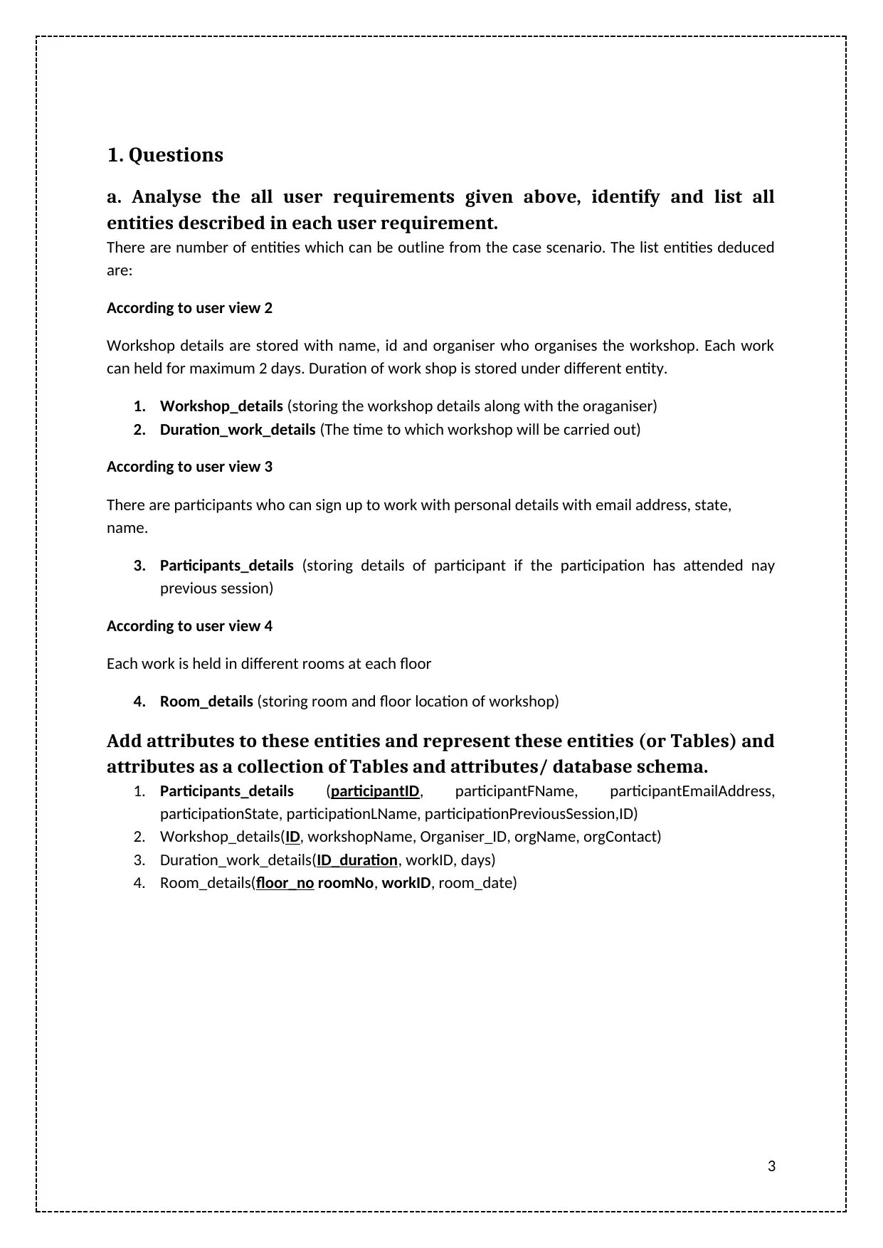
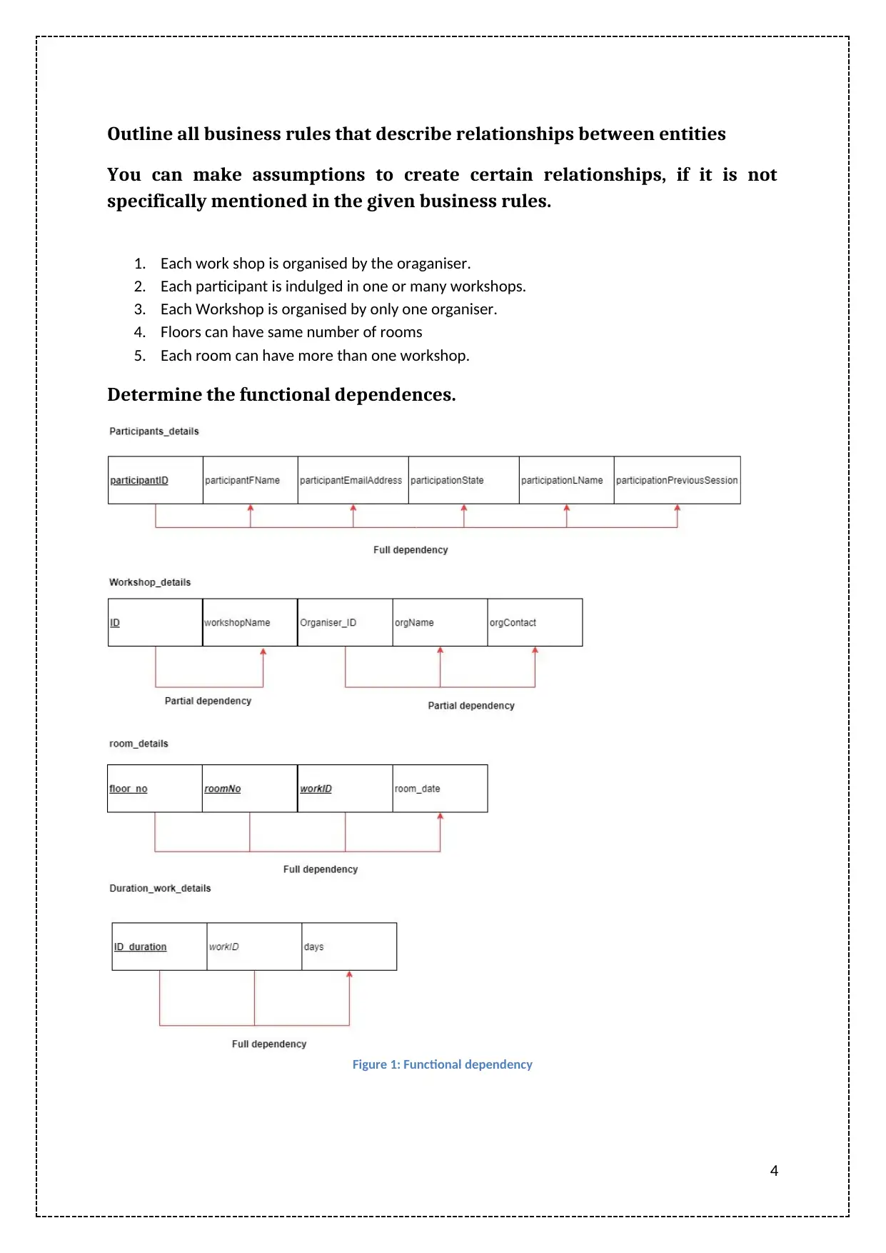
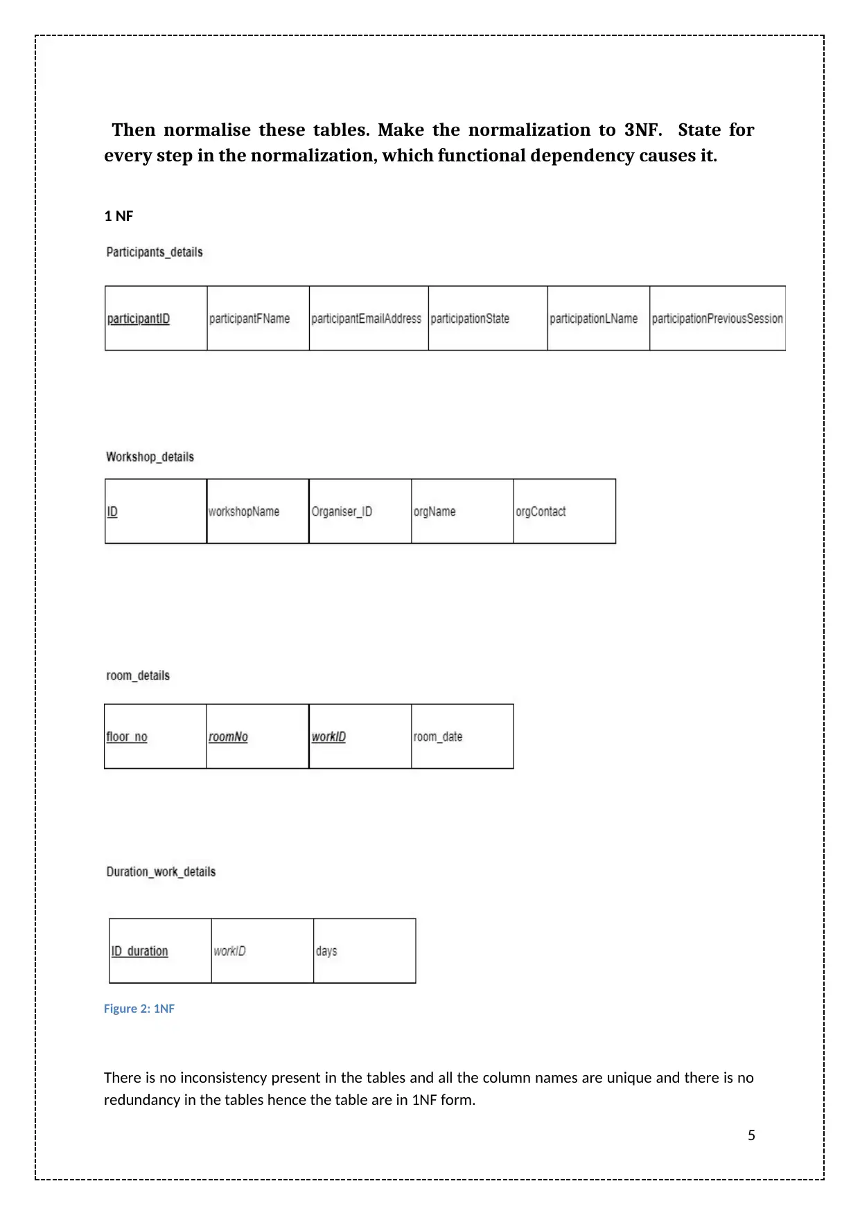
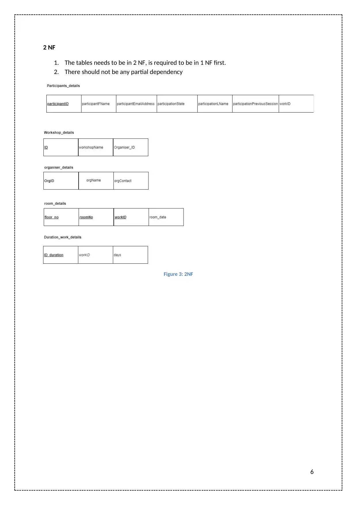
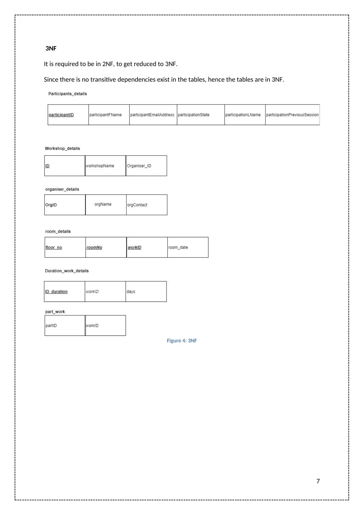
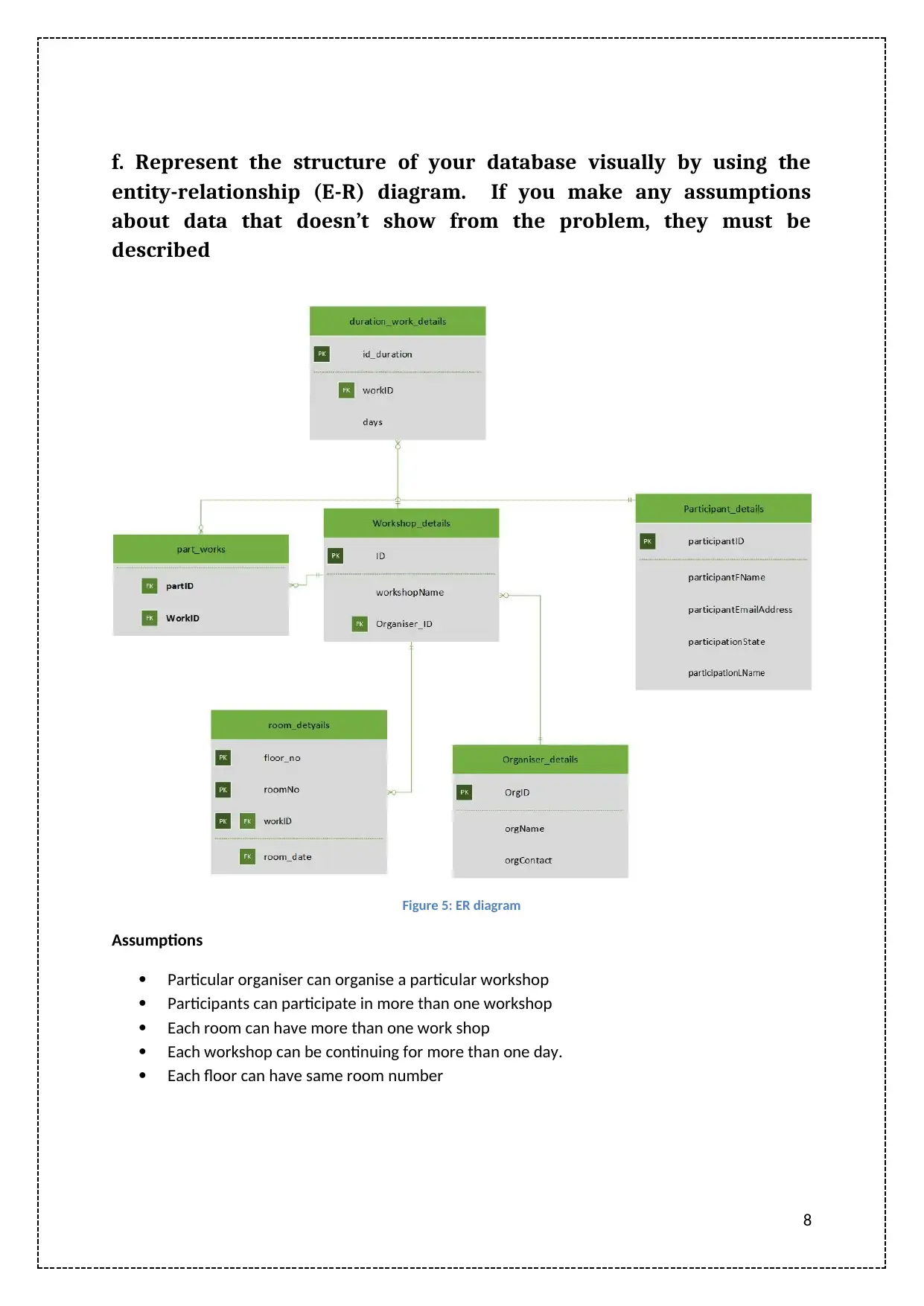
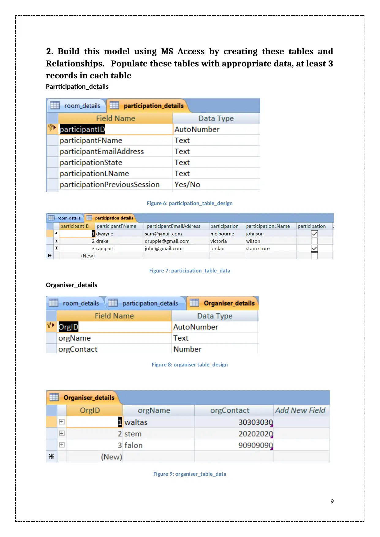
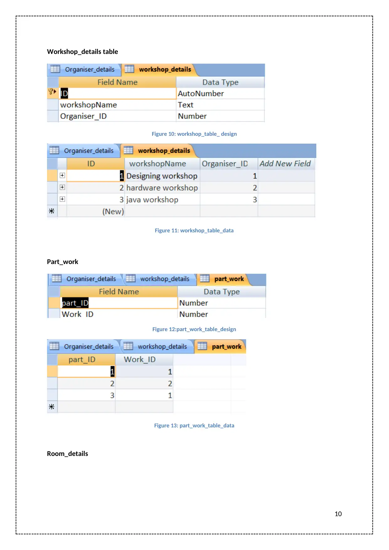
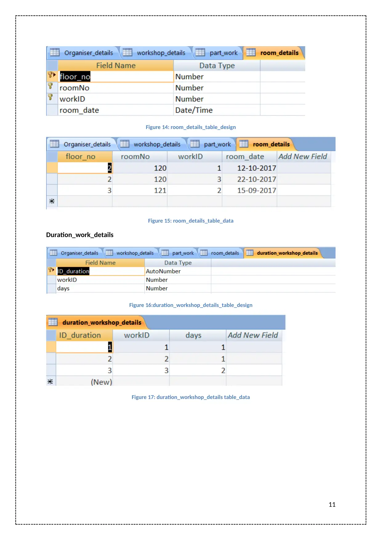
This assignment focuses on designing a database for workshop management, starting with identifying entities like Workshop Details, Duration Details, Participant Details, and Room Details. Attributes are added to these entities, and business rules are defined to establish relationships between them. Functional dependencies are determined, and the tables are normalized to 3NF, with each step explained. An entity-relationship (E-R) diagram visually represents the database structure. The model is then built using MS Access, populating tables with data, and SQL queries are written and executed to retrieve specific information. The assignment provides a comprehensive approach to database design and implementation for workshop management.

MN405: Assigment2
Paraphrase This Document
Need a fresh take? Get an instant paraphrase of this document with our AI Paraphraser

Contents
1. Questions...........................................................................................................................................3
a. Analyse the all user requirements given above, identify and list all entities described in each
user requirement...............................................................................................................................3
Add attributes to these entities and represent these entities (or Tables) and attributes as a
collection of Tables and attributes/ database schema......................................................................3
Outline all business rules that describe relationships between entities............................................4
You can make assumptions to create certain relationships, if it is not specifically mentioned in the
given business rules...........................................................................................................................4
Determine the functional dependences............................................................................................4
Then normalise these tables. Make the normalization to 3NF. State for every step in the
normalization, which functional dependency causes it.....................................................................5
f. Represent the structure of your database visually by using the entity-relationship (E-R) diagram. If
you make any assumptions about data that doesn’t show from the problem, they must be described
...............................................................................................................................................................8
2. Build this model using MS Access by creating these tables and Relationships. Populate these
tables with appropriate data, at least 3 records in each table..............................................................9
3. Write SQL queries for the following questions and execute them on the database........................12
References...........................................................................................................................................13
List of figures
Figure 1: Functional dependency...........................................................................................................4
Figure 2: 1NF.........................................................................................................................................5
Figure 3: 2NF.........................................................................................................................................6
Figure 4: 3NF.........................................................................................................................................7
Figure 5: ER diagram..............................................................................................................................8
Figure 6: participation_table_design.....................................................................................................9
Figure 7: participation_table_data........................................................................................................9
Figure 8: organiser table_design...........................................................................................................9
Figure 9: organiser_table_data..............................................................................................................9
Figure 10: workshop_table_ design.....................................................................................................10
Figure 11: workshop_table_data.........................................................................................................10
Figure 12:part_work_table_design......................................................................................................10
Figure 13: part_work_table_data........................................................................................................10
Figure 14: room_details_table_design................................................................................................11
Figure 15: room_details_table_data...................................................................................................11
Figure 16:duration_workshop_details_table_design..........................................................................11
Figure 17: duration_workshop_details table_data..............................................................................11
Figure 18: Query1................................................................................................................................12
1

Figure 19: Query 2...............................................................................................................................12
Figure 20: Query 3...............................................................................................................................12
2
Figure 20: Query 3...............................................................................................................................12
2
⊘ This is a preview!⊘
Do you want full access?
Subscribe today to unlock all pages.

Trusted by 1+ million students worldwide

1. Questions
a. Analyse the all user requirements given above, identify and list all
entities described in each user requirement.
There are number of entities which can be outline from the case scenario. The list entities deduced
are:
According to user view 2
Workshop details are stored with name, id and organiser who organises the workshop. Each work
can held for maximum 2 days. Duration of work shop is stored under different entity.
1. Workshop_details (storing the workshop details along with the oraganiser)
2. Duration_work_details (The time to which workshop will be carried out)
According to user view 3
There are participants who can sign up to work with personal details with email address, state,
name.
3. Participants_details (storing details of participant if the participation has attended nay
previous session)
According to user view 4
Each work is held in different rooms at each floor
4. Room_details (storing room and floor location of workshop)
Add attributes to these entities and represent these entities (or Tables) and
attributes as a collection of Tables and attributes/ database schema.
1. Participants_details (participantID, participantFName, participantEmailAddress,
participationState, participationLName, participationPreviousSession,ID)
2. Workshop_details(ID, workshopName, Organiser_ID, orgName, orgContact)
3. Duration_work_details(ID_duration, workID, days)
4. Room_details(floor_no roomNo, workID, room_date)
3
Paraphrase This Document
Need a fresh take? Get an instant paraphrase of this document with our AI Paraphraser

Outline all business rules that describe relationships between entities
You can make assumptions to create certain relationships, if it is not
specifically mentioned in the given business rules.
1. Each work shop is organised by the oraganiser.
2. Each participant is indulged in one or many workshops.
3. Each Workshop is organised by only one organiser.
4. Floors can have same number of rooms
5. Each room can have more than one workshop.
Determine the functional dependences.
Figure 1: Functional dependency
4

Then normalise these tables. Make the normalization to 3NF. State for
every step in the normalization, which functional dependency causes it.
1 NF
Figure 2: 1NF
There is no inconsistency present in the tables and all the column names are unique and there is no
redundancy in the tables hence the table are in 1NF form.
5
every step in the normalization, which functional dependency causes it.
1 NF
Figure 2: 1NF
There is no inconsistency present in the tables and all the column names are unique and there is no
redundancy in the tables hence the table are in 1NF form.
5
⊘ This is a preview!⊘
Do you want full access?
Subscribe today to unlock all pages.

Trusted by 1+ million students worldwide

2 NF
1. The tables needs to be in 2 NF, is required to be in 1 NF first.
2. There should not be any partial dependency
Figure 3: 2NF
6
1. The tables needs to be in 2 NF, is required to be in 1 NF first.
2. There should not be any partial dependency
Figure 3: 2NF
6
Paraphrase This Document
Need a fresh take? Get an instant paraphrase of this document with our AI Paraphraser

3NF
It is required to be in 2NF, to get reduced to 3NF.
Since there is no transitive dependencies exist in the tables, hence the tables are in 3NF.
Figure 4: 3NF
7
It is required to be in 2NF, to get reduced to 3NF.
Since there is no transitive dependencies exist in the tables, hence the tables are in 3NF.
Figure 4: 3NF
7

f. Represent the structure of your database visually by using the
entity-relationship (E-R) diagram. If you make any assumptions
about data that doesn’t show from the problem, they must be
described
Figure 5: ER diagram
Assumptions
Particular organiser can organise a particular workshop
Participants can participate in more than one workshop
Each room can have more than one work shop
Each workshop can be continuing for more than one day.
Each floor can have same room number
8
⊘ This is a preview!⊘
Do you want full access?
Subscribe today to unlock all pages.

Trusted by 1+ million students worldwide

2. Build this model using MS Access by creating these tables and
Relationships. Populate these tables with appropriate data, at least 3
records in each table
Parrticipation_details
Figure 6: participation_table_design
Figure 7: participation_table_data
Organiser_details
Figure 8: organiser table_design
Figure 9: organiser_table_data
9
Relationships. Populate these tables with appropriate data, at least 3
records in each table
Parrticipation_details
Figure 6: participation_table_design
Figure 7: participation_table_data
Organiser_details
Figure 8: organiser table_design
Figure 9: organiser_table_data
9
Paraphrase This Document
Need a fresh take? Get an instant paraphrase of this document with our AI Paraphraser

Workshop_details table
Figure 10: workshop_table_ design
Figure 11: workshop_table_data
Part_work
Figure 12:part_work_table_design
Figure 13: part_work_table_data
Room_details
10
Figure 10: workshop_table_ design
Figure 11: workshop_table_data
Part_work
Figure 12:part_work_table_design
Figure 13: part_work_table_data
Room_details
10

Figure 14: room_details_table_design
Figure 15: room_details_table_data
Duration_work_details
Figure 16:duration_workshop_details_table_design
Figure 17: duration_workshop_details table_data
11
Figure 15: room_details_table_data
Duration_work_details
Figure 16:duration_workshop_details_table_design
Figure 17: duration_workshop_details table_data
11
⊘ This is a preview!⊘
Do you want full access?
Subscribe today to unlock all pages.

Trusted by 1+ million students worldwide
1 out of 14
Related Documents
Your All-in-One AI-Powered Toolkit for Academic Success.
+13062052269
info@desklib.com
Available 24*7 on WhatsApp / Email
Unlock your academic potential
Copyright © 2020–2025 A2Z Services. All Rights Reserved. Developed and managed by ZUCOL.


