Database Design and Implementation (EER & SQL) - Assignment

Verified

Added on  2022/09/06

|12
|738
|19
Practical Assignment
AI Summary
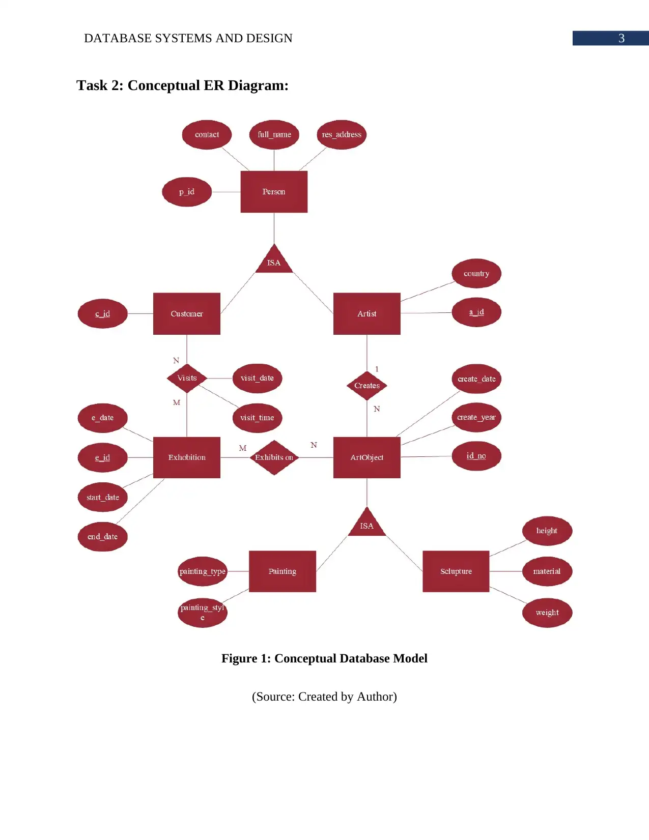
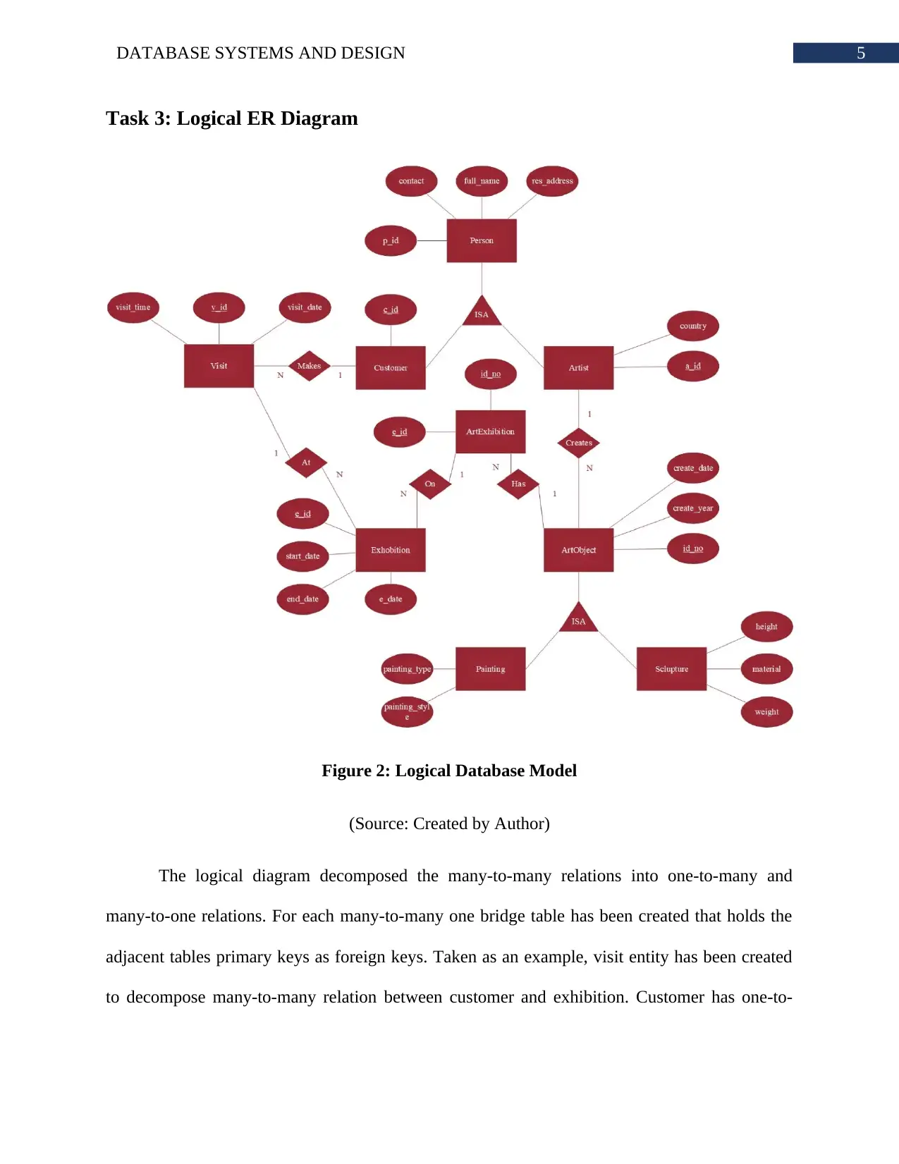
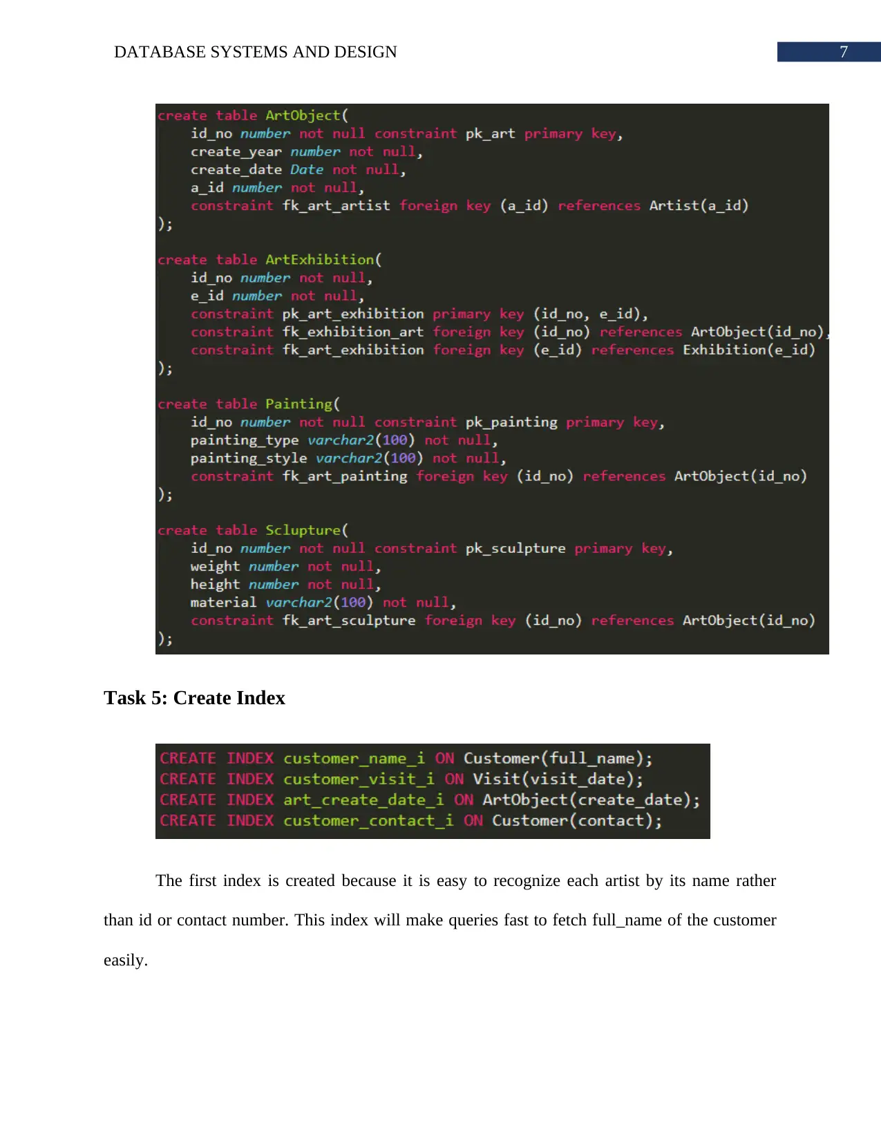
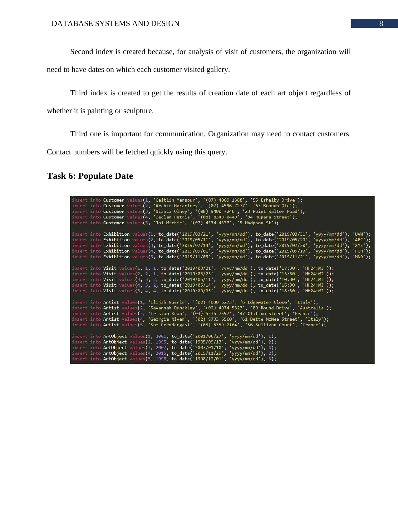
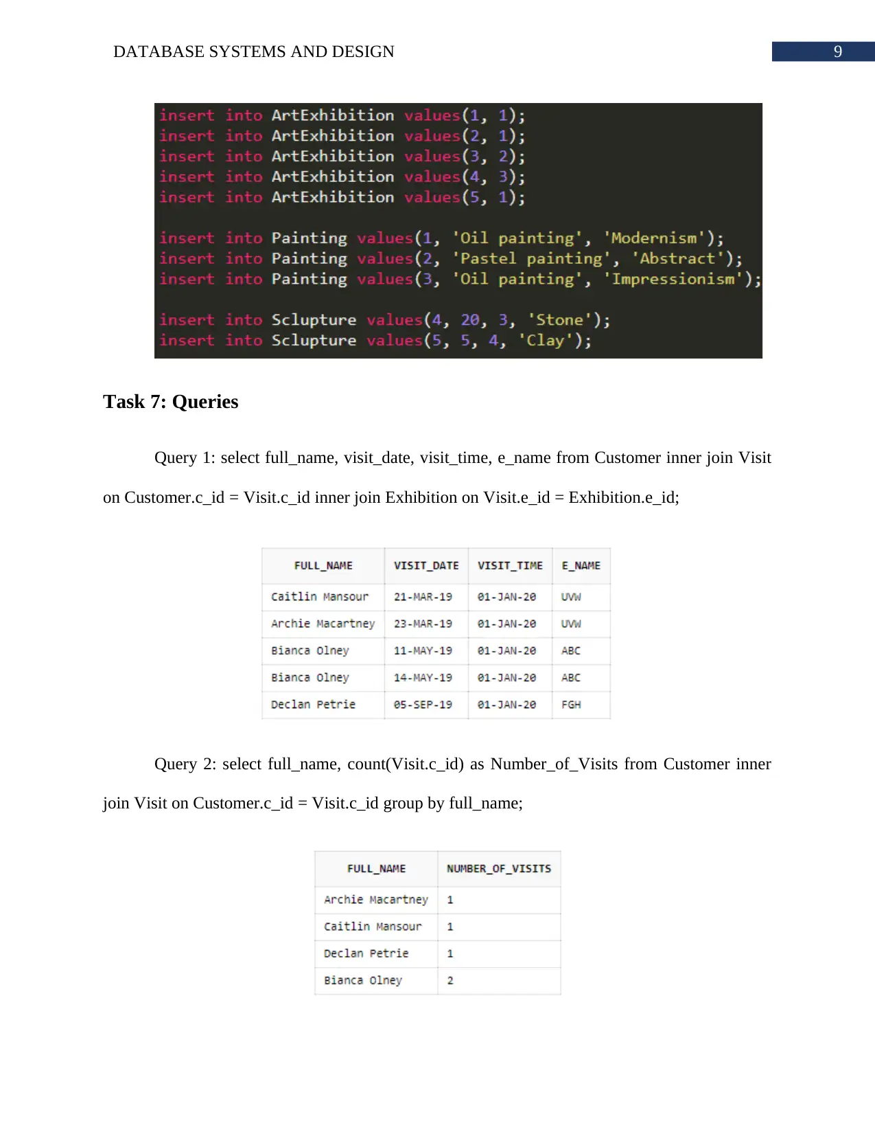
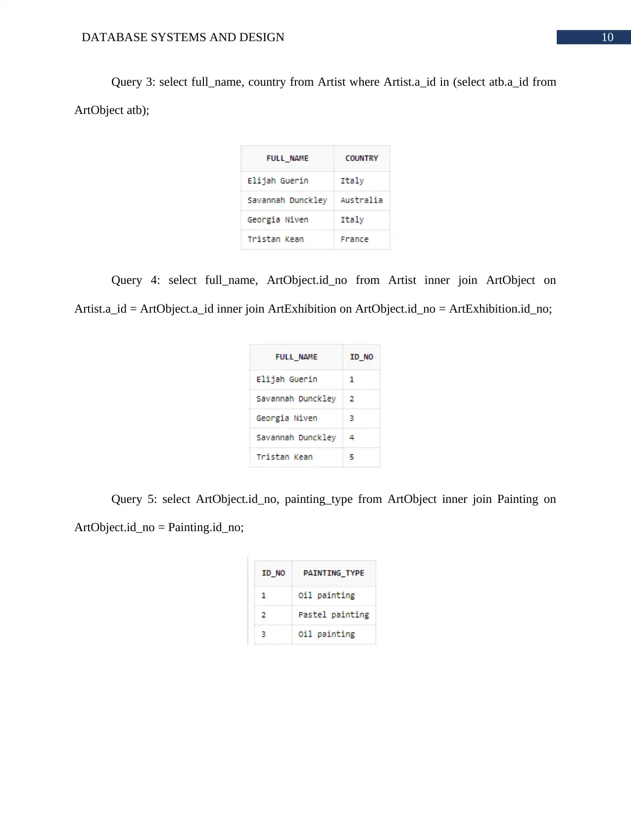
This assignment focuses on designing and implementing a database system for the National Gallery of Victoria. It begins with a scenario analysis and data requirements identification. The solution includes a conceptual ER diagram illustrating the relationships between customers, artists, exhibitions, art objects, and visits. A logical ER diagram decomposes the many-to-many relationships into one-to-many and many-to-one relationships, ensuring data integrity. The assignment details the creation of tables, including data types and constraints. It also covers index creation for optimized query performance. Sample data population is provided, followed by a set of SQL queries to retrieve specific information, such as customer visits, the number of visits per customer, artist details, and art object information. The solution demonstrates a practical understanding of database design principles, ER modeling, and SQL query writing. The assignment adheres to the guidelines provided by De Montfort University for the IMAT5103 module.
Document Page
Running heading: DATABASE SYSTEMS AND DESIGN
Database Systems and Design
Name of the Student
Name of the University
Author’s note:
tabler-icon-diamond-filled.svg

Paraphrase This Document

Need a fresh take? Get an instant paraphrase of this document with our AI Paraphraser
Document Page
1DATABASE SYSTEMS AND DESIGN
Table of Contents
Task 1: Scenario..............................................................................................................................2
Task 2: Conceptual ER Diagram:....................................................................................................3
Task 3: Logical ER Diagram...........................................................................................................5
Task 4: Create Table........................................................................................................................6
Task 5: Create Index........................................................................................................................7
Task 6: Populate Date......................................................................................................................8
Task 7: Queries................................................................................................................................9
Bibliography:.................................................................................................................................11
Document Page
2DATABASE SYSTEMS AND DESIGN
Task 1: Scenario
National Gallery of Victoria is an art gallery at Victoria wants to implement a database
management system into its premise. This system will replace its current system. Current system
does not store the details of the artist and customer who take participation in exhibitions. This is
creating issues for the organization. The organization wants the database to store details of
customer, artist, exhibition, customer visiting exhibitions and art objects.
Document Page
3DATABASE SYSTEMS AND DESIGN
Task 2: Conceptual ER Diagram:
Figure 1: Conceptual Database Model
(Source: Created by Author)
tabler-icon-diamond-filled.svg

Paraphrase This Document

Need a fresh take? Get an instant paraphrase of this document with our AI Paraphraser
Document Page
4DATABASE SYSTEMS AND DESIGN
The conceptual diagram has many-to-many relationship that will be decomposed in
logical model. This model shows that many customers can visit many exhibitions. It also shows
that many art object can be exhibited into many exhibition. Art objects are of two types such as
painting and sculpture. Customers and artists are under the category of people. Each people has a
full name, contact number and residential address.
Document Page
5DATABASE SYSTEMS AND DESIGN
Task 3: Logical ER Diagram
Figure 2: Logical Database Model
(Source: Created by Author)
The logical diagram decomposed the many-to-many relations into one-to-many and
many-to-one relations. For each many-to-many one bridge table has been created that holds the
adjacent tables primary keys as foreign keys. Taken as an example, visit entity has been created
to decompose many-to-many relation between customer and exhibition. Customer has one-to-
Document Page
6DATABASE SYSTEMS AND DESIGN
many relation with visit and visit has many-to-one relation with exhibition. This illustration
perfectly shows the real life business rule of customer visiting art gallery for exhibitions.
Task 4: Create Table
tabler-icon-diamond-filled.svg

Paraphrase This Document

Need a fresh take? Get an instant paraphrase of this document with our AI Paraphraser
Document Page
7DATABASE SYSTEMS AND DESIGN
Task 5: Create Index
The first index is created because it is easy to recognize each artist by its name rather
than id or contact number. This index will make queries fast to fetch full_name of the customer
easily.
Document Page
8DATABASE SYSTEMS AND DESIGN
Second index is created because, for analysis of visit of customers, the organization will
need to have dates on which each customer visited gallery.
Third index is created to get the results of creation date of each art object regardless of
whether it is painting or sculpture.
Third one is important for communication. Organization may need to contact customers.
Contact numbers will be fetched quickly using this query.
Task 6: Populate Date
Document Page
9DATABASE SYSTEMS AND DESIGN
Task 7: Queries
Query 1: select full_name, visit_date, visit_time, e_name from Customer inner join Visit
on Customer.c_id = Visit.c_id inner join Exhibition on Visit.e_id = Exhibition.e_id;
Query 2: select full_name, count(Visit.c_id) as Number_of_Visits from Customer inner
join Visit on Customer.c_id = Visit.c_id group by full_name;
tabler-icon-diamond-filled.svg

Paraphrase This Document

Need a fresh take? Get an instant paraphrase of this document with our AI Paraphraser
Document Page
10DATABASE SYSTEMS AND DESIGN
Query 3: select full_name, country from Artist where Artist.a_id in (select atb.a_id from
ArtObject atb);
Query 4: select full_name, ArtObject.id_no from Artist inner join ArtObject on
Artist.a_id = ArtObject.a_id inner join ArtExhibition on ArtObject.id_no = ArtExhibition.id_no;
Query 5: select ArtObject.id_no, painting_type from ArtObject inner join Painting on
ArtObject.id_no = Painting.id_no;
Document Page
11DATABASE SYSTEMS AND DESIGN
Bibliography:
Aldahdooh, R. and Naser, S.S.A., 2017. Development and Evaluation of the Oracle Intelligent
Tutoring System (OITS).
Reprintsev, A., Reprintsev, A. and Gennick, 2018. Oracle SQL Revealed. Apress.
Shrivastava, R., Saxena, G.K. and Patidar, K., 2017. Implementation Of Unified Query For Big
Database Using Sql On Oracle Platform. International Journal of Current Innovation Research,
3(03), pp.616-621.
Sethy, R., Dash, S.K. and Panda, M., 2016, December. Performance Comparison Between
Apache Hive and Oracle SQL for Big Data Analytics. In International Conference on Soft
Computing and Pattern Recognition (pp. 130-141). Springer, Cham.
chevron_up_icon
1 out of 12
circle_padding
hide_on_mobile
zoom_out_icon
[object Object]