Database Management System Assignment: ERD, Design and Rules

Verified

Added on  2021/04/24

|6
|665
|49
Homework Assignment
AI Summary
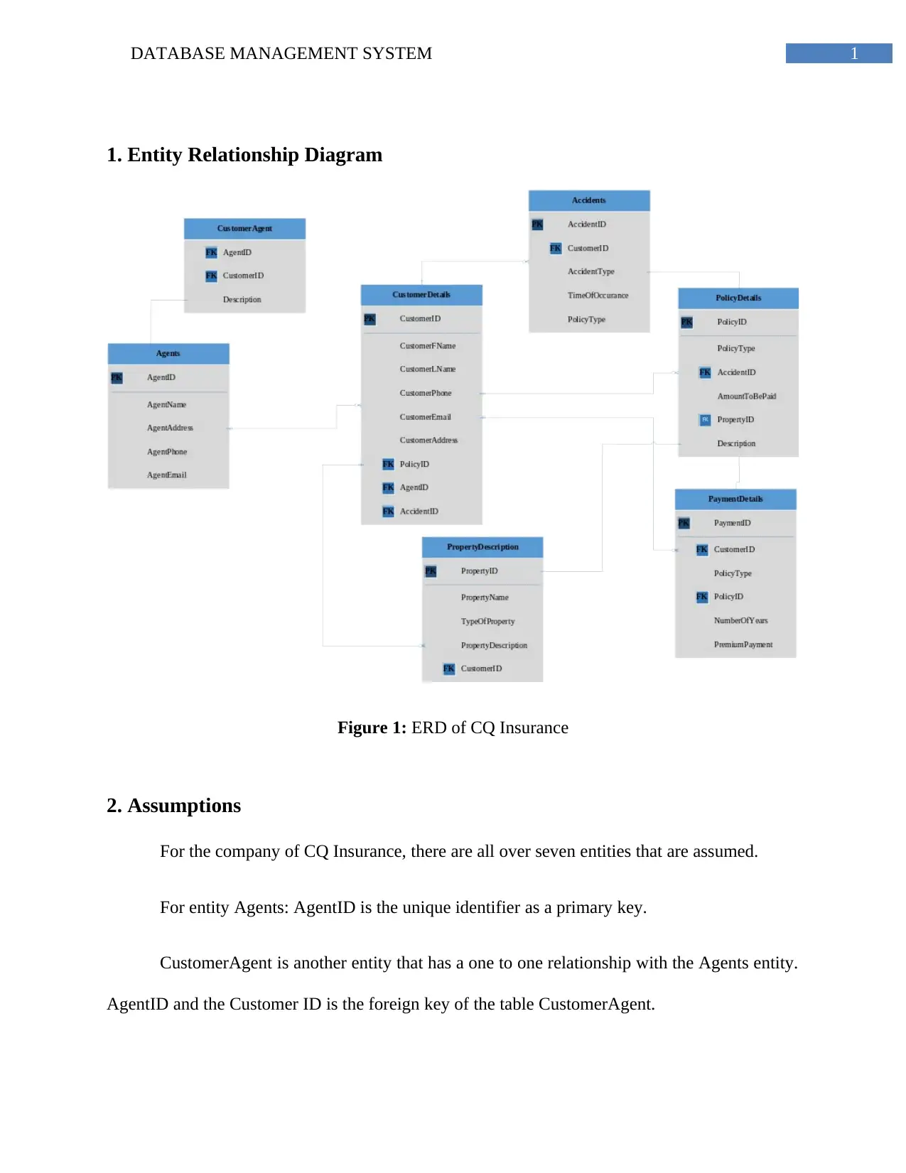
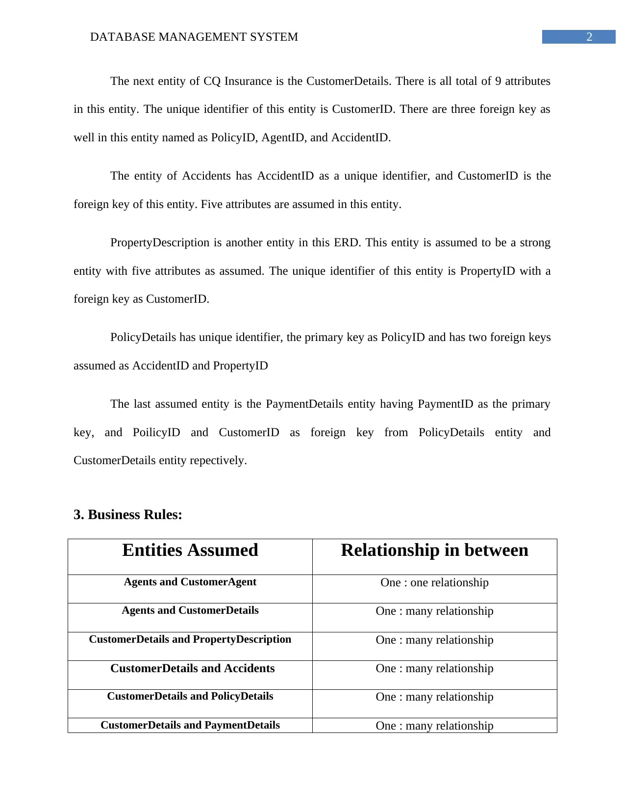
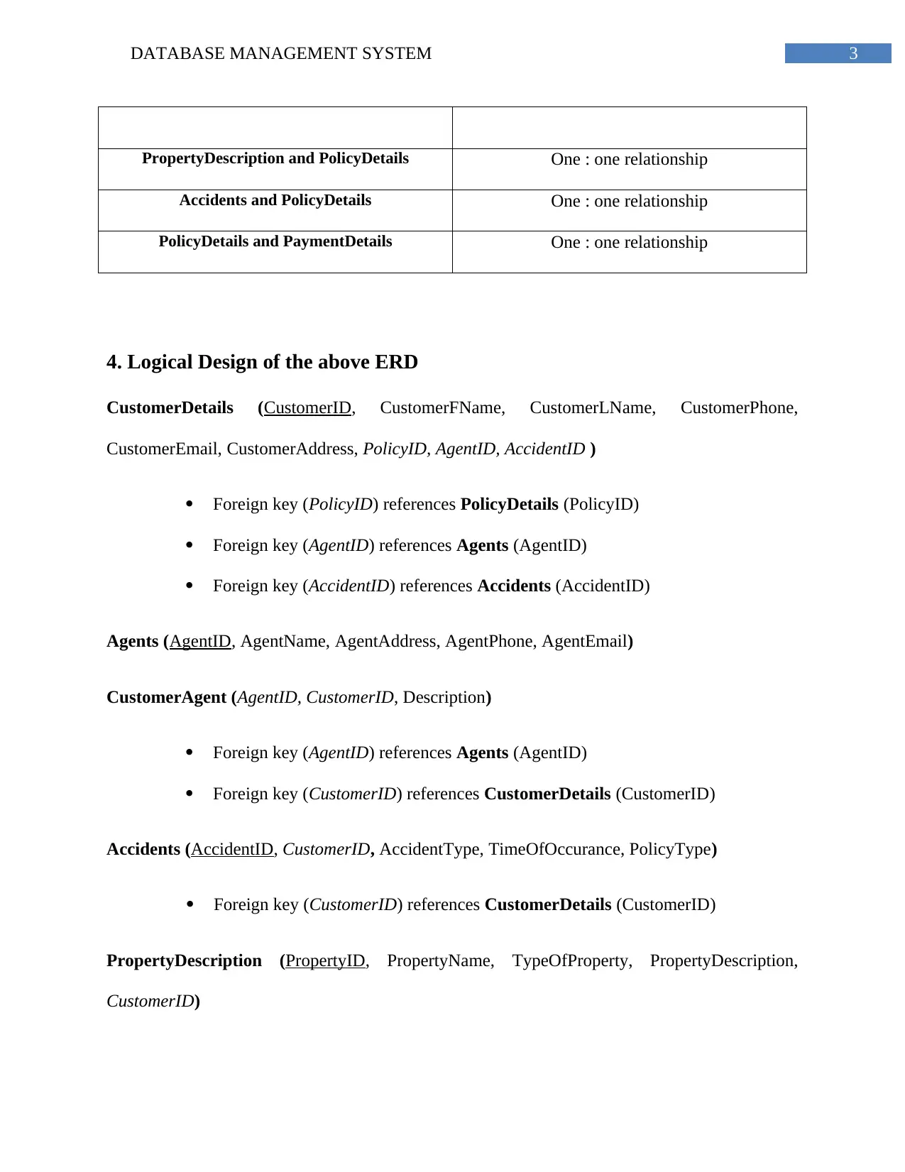
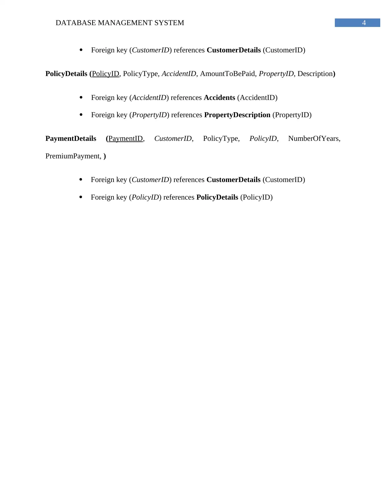
This assignment solution focuses on the design of a database management system for CQ Insurance. It begins with an Entity Relationship Diagram (ERD) illustrating the entities, attributes, and relationships within the system, including Agents, Customers, Accidents, Property Descriptions, Policy Details, and Payment Details. Assumptions about the entities and their attributes are clearly defined. The document then outlines the business rules governing the relationships between these entities, such as the one-to-many relationships between Customers and various other entities like Policies and Accidents. Following this, the logical design of the database is presented, including the table structures with attributes, primary keys, and foreign keys, ensuring data integrity and efficient retrieval. Finally, a bibliography of relevant sources is provided to support the design choices and methodologies employed. This assignment provides a comprehensive overview of database design principles and their application in a real-world scenario.
Document Page
Running head: DATABASE MANAGEMENT SYSTEM
Database Management System
Name of Student-
Name of University-
Author’s Note-
tabler-icon-diamond-filled.svg

Paraphrase This Document

Need a fresh take? Get an instant paraphrase of this document with our AI Paraphraser
Document Page
1DATABASE MANAGEMENT SYSTEM
1. Entity Relationship Diagram
Figure 1: ERD of CQ Insurance
2. Assumptions
For the company of CQ Insurance, there are all over seven entities that are assumed.
For entity Agents: AgentID is the unique identifier as a primary key.
CustomerAgent is another entity that has a one to one relationship with the Agents entity.
AgentID and the Customer ID is the foreign key of the table CustomerAgent.
Document Page
2DATABASE MANAGEMENT SYSTEM
The next entity of CQ Insurance is the CustomerDetails. There is all total of 9 attributes
in this entity. The unique identifier of this entity is CustomerID. There are three foreign key as
well in this entity named as PolicyID, AgentID, and AccidentID.
The entity of Accidents has AccidentID as a unique identifier, and CustomerID is the
foreign key of this entity. Five attributes are assumed in this entity.
PropertyDescription is another entity in this ERD. This entity is assumed to be a strong
entity with five attributes as assumed. The unique identifier of this entity is PropertyID with a
foreign key as CustomerID.
PolicyDetails has unique identifier, the primary key as PolicyID and has two foreign keys
assumed as AccidentID and PropertyID
The last assumed entity is the PaymentDetails entity having PaymentID as the primary
key, and PoilicyID and CustomerID as foreign key from PolicyDetails entity and
CustomerDetails entity repectively.
3. Business Rules:
Entities Assumed Relationship in between
Agents and CustomerAgent One : one relationship
Agents and CustomerDetails One : many relationship
CustomerDetails and PropertyDescription One : many relationship
CustomerDetails and Accidents One : many relationship
CustomerDetails and PolicyDetails One : many relationship
CustomerDetails and PaymentDetails One : many relationship
Document Page
3DATABASE MANAGEMENT SYSTEM
PropertyDescription and PolicyDetails One : one relationship
Accidents and PolicyDetails One : one relationship
PolicyDetails and PaymentDetails One : one relationship
4. Logical Design of the above ERD
CustomerDetails (CustomerID, CustomerFName, CustomerLName, CustomerPhone,
CustomerEmail, CustomerAddress, PolicyID, AgentID, AccidentID )
Foreign key (PolicyID) references PolicyDetails (PolicyID)
Foreign key (AgentID) references Agents (AgentID)
Foreign key (AccidentID) references Accidents (AccidentID)
Agents (AgentID, AgentName, AgentAddress, AgentPhone, AgentEmail)
CustomerAgent (AgentID, CustomerID, Description)
Foreign key (AgentID) references Agents (AgentID)
Foreign key (CustomerID) references CustomerDetails (CustomerID)
Accidents (AccidentID, CustomerID, AccidentType, TimeOfOccurance, PolicyType)
Foreign key (CustomerID) references CustomerDetails (CustomerID)
PropertyDescription (PropertyID, PropertyName, TypeOfProperty, PropertyDescription,
CustomerID)
tabler-icon-diamond-filled.svg

Paraphrase This Document

Need a fresh take? Get an instant paraphrase of this document with our AI Paraphraser
Document Page
4DATABASE MANAGEMENT SYSTEM
Foreign key (CustomerID) references CustomerDetails (CustomerID)
PolicyDetails (PolicyID, PolicyType, AccidentID, AmountToBePaid, PropertyID, Description)
Foreign key (AccidentID) references Accidents (AccidentID)
Foreign key (PropertyID) references PropertyDescription (PropertyID)
PaymentDetails (PaymentID, CustomerID, PolicyType, PolicyID, NumberOfYears,
PremiumPayment, )
Foreign key (CustomerID) references CustomerDetails (CustomerID)
Foreign key (PolicyID) references PolicyDetails (PolicyID)
Document Page
5DATABASE MANAGEMENT SYSTEM
Bibliography
Al-Masree, H.K., 2015. Extracting Entity Relationship Diagram (ERD) from relational database
schema. International Journal of Database Theory and Application, 8(3), pp.15-26.
Yang, L. and Cao, L., 2016. The Effect of MySQL Workbench in Teaching Entity-Relationship
Diagram (ERD) to Relational Schema Mapping. International Journal of Modern Education and
Computer Science, 8(7), p.1.
Kruse, S.L.K. and Wells, M.G., 2016. Optionality of ERD Relationships: Project for the
Introduction to Database Course. In Proceedings of the EDSIG Conference ISSN (Vol. 2473, p.
3857).
chevron_up_icon
1 out of 6
circle_padding
hide_on_mobile
zoom_out_icon
[object Object]