Database System Modelling for Granite Sales Company Database

Verified

Added on  2023/05/27

|8
|1098
|157
Project
AI Summary
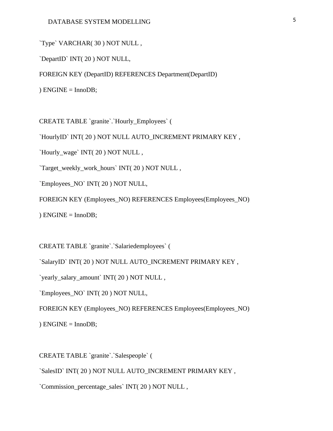
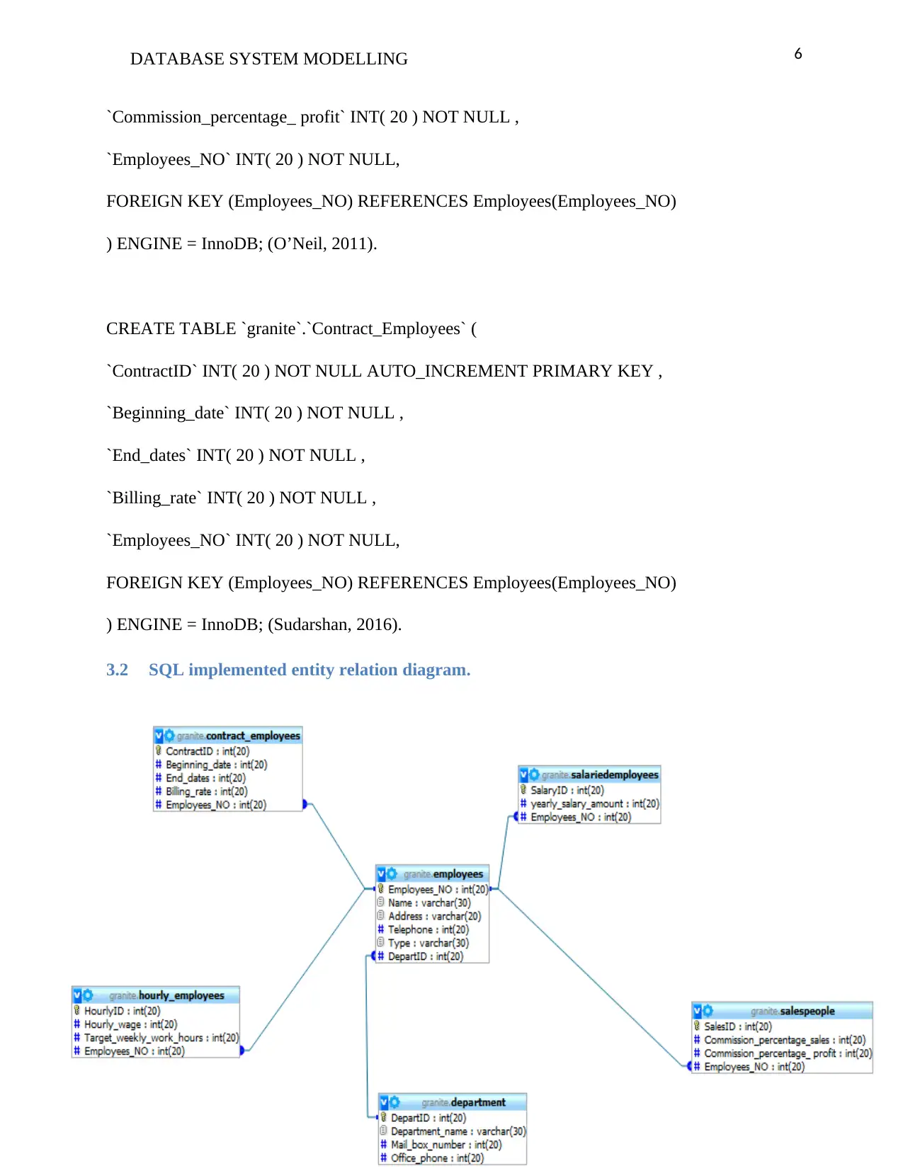
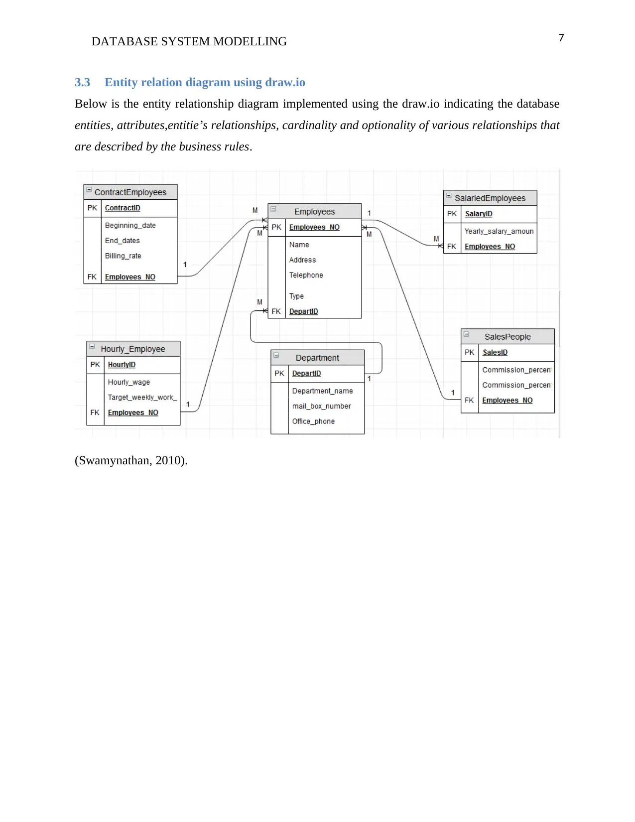
This project focuses on database system modelling for the Granite Sales Company. The assignment includes the development of business rules based on a given scenario, detailing the relationships between departments and employees. It involves creating an Entity Relationship Diagram (ERD) to visually represent the database structure, showcasing entities such as departments, employees, hourly employees, salaried employees, salespeople, and contract employees, along with their attributes and relationships. The solution presents an SQL query to implement the database, followed by an SQL-implemented ERD and another ERD created using draw.io, providing multiple perspectives on the database design. The project demonstrates the practical application of database design principles and the use of SQL for database creation and management, providing a comprehensive understanding of database modelling concepts.
Document Page
Running head: DATABASE SYSTEM MODELLING 1
Database System Modelling
Granite Sales Company Database System
[Student Name]
[University Name]
tabler-icon-diamond-filled.svg

Paraphrase This Document

Need a fresh take? Get an instant paraphrase of this document with our AI Paraphraser
Document Page
2DATABASE SYSTEM MODELLING
Table of Contents
1 Introduction.........................................................................................................................................3
2 Task 1: Possible business rules............................................................................................................3
3 Task 2: The granite sales company Entity Relationship Diagrams (ERDs).........................................4
3.1 SQL query...................................................................................................................................4
3.2 SQL implemented entity relation diagram...................................................................................6
3.3 Entity relation diagram using draw.io..........................................................................................7
4 Reference.............................................................................................................................................8
Document Page
3DATABASE SYSTEM MODELLING
1 Introduction
The granite sales company is a growing company and has a number of employees and they are
allocated n various departments however the company keeps the details of the employees and the
departments as well.
There are various employees in one department but the employees are only allocated in one
department, there are two major categories of employees who are either salaried, hourly or
contract employees.
The salaried employees can as well act as sales people who get commissions on top of their
monthly salaries and their annual salaries are recorded in the system, however the sales
commissions on sales and profits are all captured in the system.
Below are the various tables obtained from the granite sales company scenario.
i. Department(DepartID, department_name, mail_box_number, office_phone)
ii. Employees(Employees_NO,Name,address, telephone,type, DepartID)
iii. Hourly_Employees(HourlyID,hourly_wage,target_weekly_work_hours,
Employees_NO) (Kahate, 2013).
iv. Salariedemployees(SalaryID, yearly_salary_amount, Employees_NO)
v. Salespeople(SalesID, commission_percentage_sales, commission_percentage_ profit,
Employees_NO)
vi. Contract_Employees(ContractID,beginning_date,end_dates,billing_rate,
Employees_NO)
2 Task 1: Possible business rules
Below are the various business rules for the granite sales company.
i. The company can have many departments.
ii. The company can have many employees.
iii. One department can have many employees (Carlos, 2017).
iv. One employee belongs only to one department.
v. There are many types of employees.
Document Page
4DATABASE SYSTEM MODELLING
vi. Salaried employee can be salespeople.
vii. The salespeople cannot be salaried employees.
viii. Salespeople get paid on sales and profit commissions.
ix. Employees can be salespersons.
x. Employees can be hourly workers.
xi. Employees can be contract workers.
3 Task 2: The granite sales company Entity Relationship Diagrams (ERDs)
The entity relationship diagram shows how the various entities relate with each other, however in
this case the database had been implemented using the SQL query below.
3.1 SQL query
CREATE DATABASE `granite` ;
use granite;
CREATE TABLE `granite`.`Department` (
`DepartID` INT( 20 ) NOT NULL AUTO_INCREMENT PRIMARY KEY ,
`Department_name` VARCHAR( 30 ) NOT NULL ,
`Mail_box_number` INT( 20 ) NOT NULL ,
`Office_phone` INT( 20 ) NOT NULL
) ENGINE = InnoDB; (Kumar,2011).
CREATE TABLE `granite`.`Employees` (
`Employees_NO` INT( 20 ) NOT NULL AUTO_INCREMENT PRIMARY KEY ,
`Name` VARCHAR( 30 ) NOT NULL ,
`Address` VARCHAR( 20 ) NOT NULL ,
`Telephone` INT( 20 ) NOT NULL ,
tabler-icon-diamond-filled.svg

Paraphrase This Document

Need a fresh take? Get an instant paraphrase of this document with our AI Paraphraser
Document Page
5DATABASE SYSTEM MODELLING
`Type` VARCHAR( 30 ) NOT NULL ,
`DepartID` INT( 20 ) NOT NULL,
FOREIGN KEY (DepartID) REFERENCES Department(DepartID)
) ENGINE = InnoDB;
CREATE TABLE `granite`.`Hourly_Employees` (
`HourlyID` INT( 20 ) NOT NULL AUTO_INCREMENT PRIMARY KEY ,
`Hourly_wage` INT( 20 ) NOT NULL ,
`Target_weekly_work_hours` INT( 20 ) NOT NULL ,
`Employees_NO` INT( 20 ) NOT NULL,
FOREIGN KEY (Employees_NO) REFERENCES Employees(Employees_NO)
) ENGINE = InnoDB;
CREATE TABLE `granite`.`Salariedemployees` (
`SalaryID` INT( 20 ) NOT NULL AUTO_INCREMENT PRIMARY KEY ,
`yearly_salary_amount` INT( 20 ) NOT NULL ,
`Employees_NO` INT( 20 ) NOT NULL,
FOREIGN KEY (Employees_NO) REFERENCES Employees(Employees_NO)
) ENGINE = InnoDB;
CREATE TABLE `granite`.`Salespeople` (
`SalesID` INT( 20 ) NOT NULL AUTO_INCREMENT PRIMARY KEY ,
`Commission_percentage_sales` INT( 20 ) NOT NULL ,
Document Page
6DATABASE SYSTEM MODELLING
`Commission_percentage_ profit` INT( 20 ) NOT NULL ,
`Employees_NO` INT( 20 ) NOT NULL,
FOREIGN KEY (Employees_NO) REFERENCES Employees(Employees_NO)
) ENGINE = InnoDB; (O’Neil, 2011).
CREATE TABLE `granite`.`Contract_Employees` (
`ContractID` INT( 20 ) NOT NULL AUTO_INCREMENT PRIMARY KEY ,
`Beginning_date` INT( 20 ) NOT NULL ,
`End_dates` INT( 20 ) NOT NULL ,
`Billing_rate` INT( 20 ) NOT NULL ,
`Employees_NO` INT( 20 ) NOT NULL,
FOREIGN KEY (Employees_NO) REFERENCES Employees(Employees_NO)
) ENGINE = InnoDB; (Sudarshan, 2016).
3.2 SQL implemented entity relation diagram.
Document Page
7DATABASE SYSTEM MODELLING
3.3 Entity relation diagram using draw.io
Below is the entity relationship diagram implemented using the draw.io indicating the database
entities, attributes,entitie’s relationships, cardinality and optionality of various relationships that
are described by the business rules.
(Swamynathan, 2010).
tabler-icon-diamond-filled.svg

Paraphrase This Document

Need a fresh take? Get an instant paraphrase of this document with our AI Paraphraser
Document Page
8DATABASE SYSTEM MODELLING
4 Reference
Swamynathan,S.(2010). An Introduction to Database Systems. Pearson Education: New York.
Sudarshan.S.(2016). Database System Concepts. McGraw-Hill Education:India.
Kumar.S.(2011).Database Systems Concepts, Designs and Application. Pearson Education:
New York.
Carlos.C.(2017).Database Systems Design, Implementation and Management. Thomson
Learning-Course Technology: New York.
O’Neil.E.(2011). Database Principles, Programming and Performance. Harcourt Asia Pte. Ltd:
New York.
Kahate.A.(2013). Introduction to Database Management Systems.Pearson Education: New York.
chevron_up_icon
1 out of 8
circle_padding
hide_on_mobile
zoom_out_icon
[object Object]