EAC4025-N: Analysis of DC-AC Converters Design and Operation Report
VerifiedAdded on 2021/12/07
|30
|4918
|151
Report
AI Summary
This lab report, focusing on EAC4025-N, examines parametric voltage transmission and high power systems using a didactic hardware system. It covers DC to AC power transmission and high-voltage power transmission, including single HVDC converter behavior, the influence of DC voltage on AC variables, and power flow analysis with close coupling. The report explores amplitude modulation and fundamental frequency control, analyzing their impact on voltage and current characteristics. Experiments were conducted to measure amplitude modulation and determine fundamental frequencies. The report includes circuit diagrams, procedures, results, and graphical illustrations, offering a comprehensive understanding of DC-AC converter design and operation, including discussions on switching frequency, synchronous modulation, and the application of PWM for voltage amplitude adjustment. The report also references several research papers to support its findings.
Power Electronics 1
Power Electronics: EAC4025-N
Design and Operation of DC-AC Converters
by Student’s Name
Code + Course Name
Professor’s Name
University Name
City, State
Date
Power Electronics: EAC4025-N
Design and Operation of DC-AC Converters
by Student’s Name
Code + Course Name
Professor’s Name
University Name
City, State
Date
Paraphrase This Document
Need a fresh take? Get an instant paraphrase of this document with our AI Paraphraser
Power Electronics 2
Summary
This paper aims at examining the parametric voltage transmission as well as high powers in the
systems. The lab report mainly carried out via the application of makeable didactic hardware
system. This lab report mainly comprises of two key elements and aspects. The key areas
tackled in the lab report include the DC to AC power transmissions as well as the High voltage
power transmission section. The firsts of the lab work explores on different aspects such as the
single HVDC converter behaviour as well as the determination of the influence of DC voltage on
the overall AC variables. The analysis must be depicted in line with the inductive and capacitive
reactive current and supply. The first lab assignments also examines the power flow which one
depicts in line with the close coupling as well as the overall converter stations. Furthermore, the
section also demarcates on the Operation of the amplitude modulation in the circuits and the
overall effects and impacts documented as well as illustrated in the graphical illustrations. On the
other hand, the second section of this lab report depicts on the analysis of the fundamental
frequency control and this analysis poses on the DC voltage and the impacts in line with the
conversion into the alternating current. In essence, it is important to note that High-voltage
Alternating current transmission often referred to as high-voltage direct-current and this entails
the converter station as well as the overall transmission line. The analogy aims at converting the
conventional electricity as well as alternative grid.
Introduction
DC to AC Converter
Preferably, power inverters often requires makeable control amount in ensuring that the system
operates efficiently as well as safely. Subsequently, it is important to note that DC to AC
converter has five key simulations in line with the sub-system and this helps in controlling the
Power Electronics 3
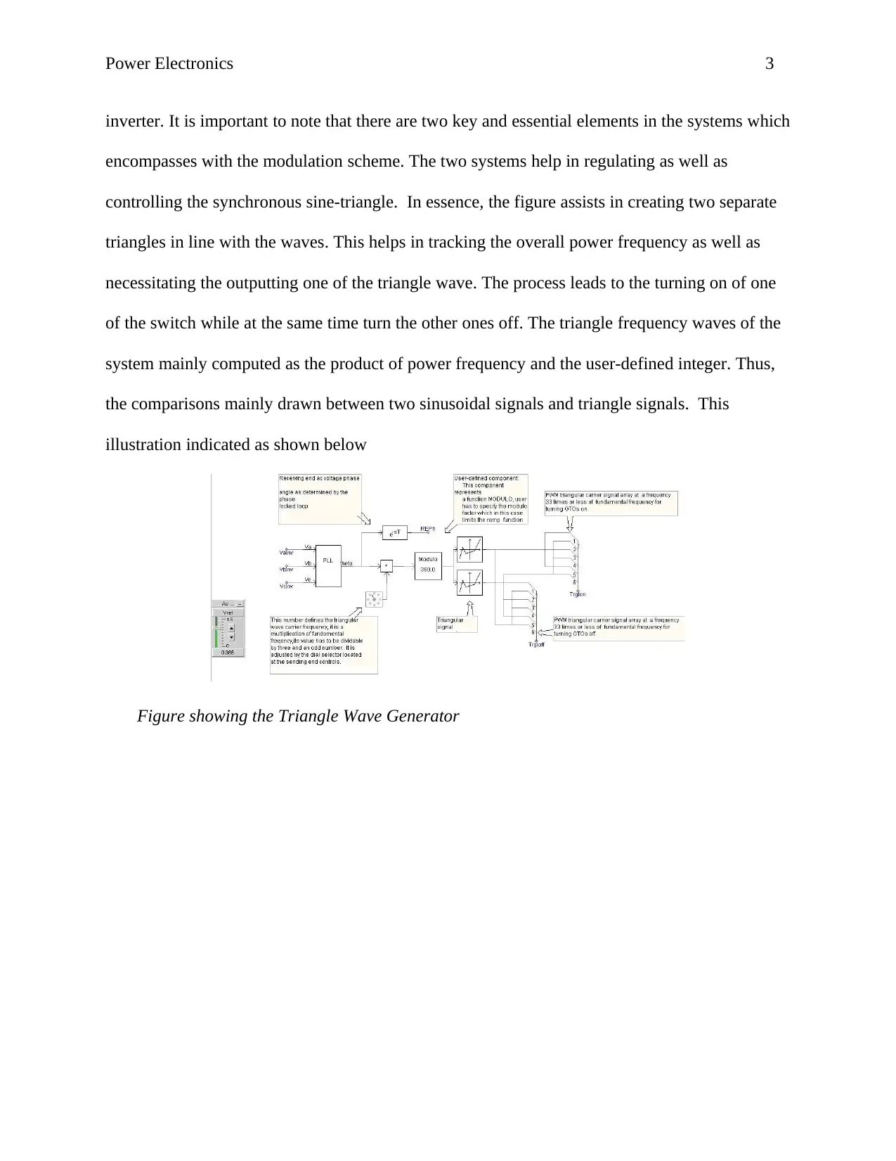
inverter. It is important to note that there are two key and essential elements in the systems which
encompasses with the modulation scheme. The two systems help in regulating as well as
controlling the synchronous sine-triangle. In essence, the figure assists in creating two separate
triangles in line with the waves. This helps in tracking the overall power frequency as well as
necessitating the outputting one of the triangle wave. The process leads to the turning on of one
of the switch while at the same time turn the other ones off. The triangle frequency waves of the
system mainly computed as the product of power frequency and the user-defined integer. Thus,
the comparisons mainly drawn between two sinusoidal signals and triangle signals. This
illustration indicated as shown below
Figure showing the Triangle Wave Generator
⊘ This is a preview!⊘
Do you want full access?
Subscribe today to unlock all pages.

Trusted by 1+ million students worldwide
Power Electronics 4
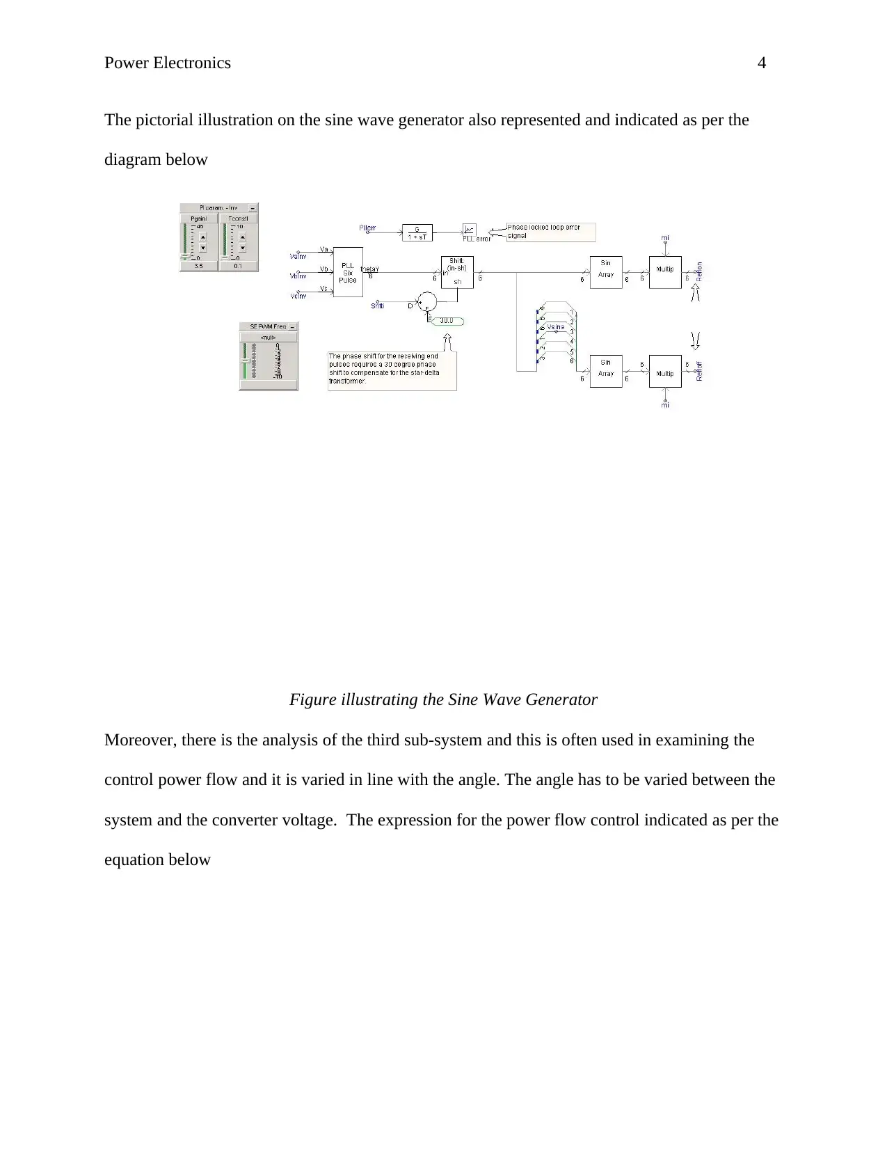
The pictorial illustration on the sine wave generator also represented and indicated as per the
diagram below
Figure illustrating the Sine Wave Generator
Moreover, there is the analysis of the third sub-system and this is often used in examining the
control power flow and it is varied in line with the angle. The angle has to be varied between the
system and the converter voltage. The expression for the power flow control indicated as per the
equation below
Paraphrase This Document
Need a fresh take? Get an instant paraphrase of this document with our AI Paraphraser

Power Electronics 5
Where
V conv is the effective converter voltage
Where
V conv is the effective converter voltage

Power Electronics 6
V sys is the system voltage
X is theline reactance
V sys is the system voltage
X is theline reactance
⊘ This is a preview!⊘
Do you want full access?
Subscribe today to unlock all pages.

Trusted by 1+ million students worldwide
Power Electronics 7
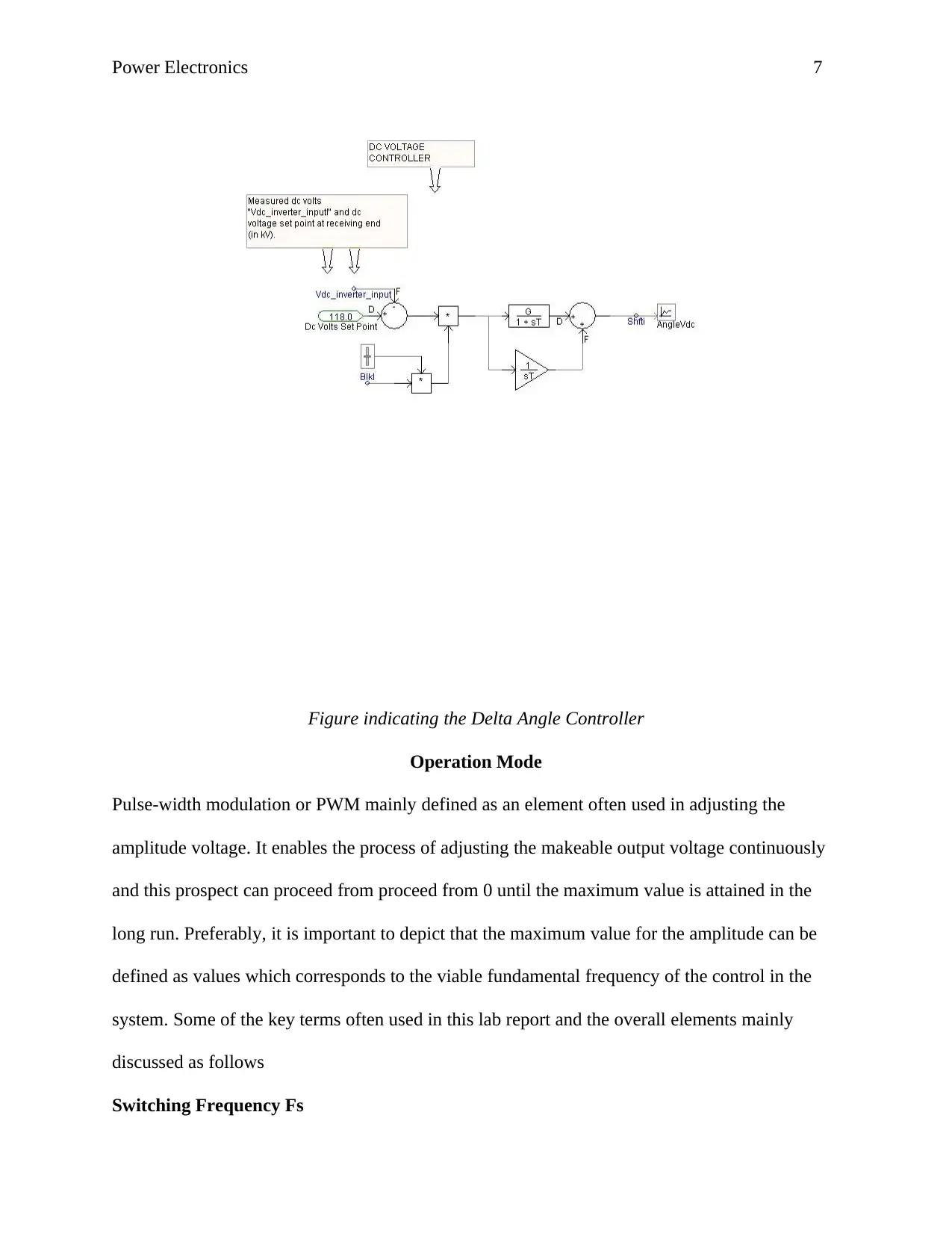
Figure indicating the Delta Angle Controller
Operation Mode
Pulse-width modulation or PWM mainly defined as an element often used in adjusting the
amplitude voltage. It enables the process of adjusting the makeable output voltage continuously
and this prospect can proceed from proceed from 0 until the maximum value is attained in the
long run. Preferably, it is important to depict that the maximum value for the amplitude can be
defined as values which corresponds to the viable fundamental frequency of the control in the
system. Some of the key terms often used in this lab report and the overall elements mainly
discussed as follows
Switching Frequency Fs
Paraphrase This Document
Need a fresh take? Get an instant paraphrase of this document with our AI Paraphraser
Power Electronics 8
This frequency refers to the one which necessitates the switching of the power semiconductor
either on or off in due course. Furthermore, it is important to note that the system has a switching
cycle. This comprises of the elements for the switch-on operation as well as switch-off operation
and this is conducted by the power of semiconductor jointly.
Switching or Cycle Count q
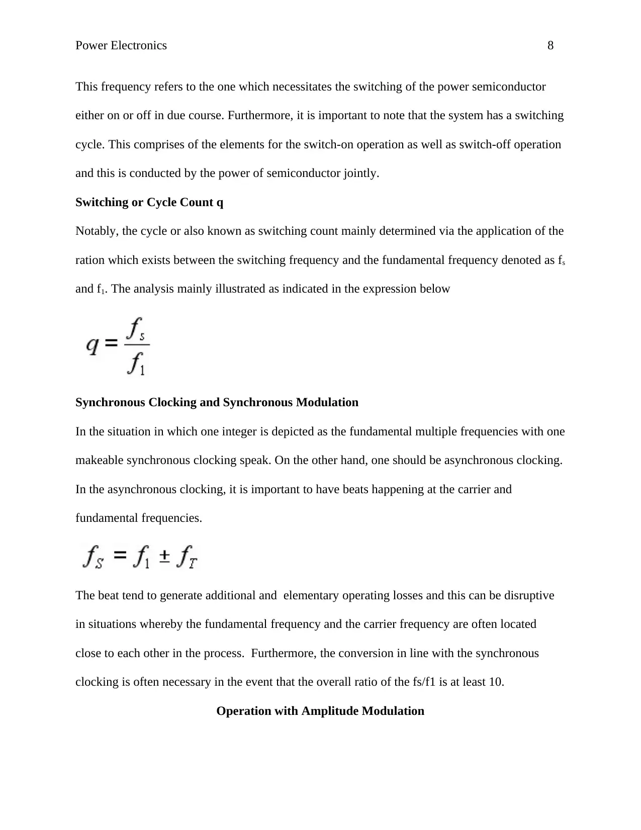
Notably, the cycle or also known as switching count mainly determined via the application of the
ration which exists between the switching frequency and the fundamental frequency denoted as fs
and f1. The analysis mainly illustrated as indicated in the expression below
Synchronous Clocking and Synchronous Modulation
In the situation in which one integer is depicted as the fundamental multiple frequencies with one
makeable synchronous clocking speak. On the other hand, one should be asynchronous clocking.
In the asynchronous clocking, it is important to have beats happening at the carrier and
fundamental frequencies.
The beat tend to generate additional and elementary operating losses and this can be disruptive
in situations whereby the fundamental frequency and the carrier frequency are often located
close to each other in the process. Furthermore, the conversion in line with the synchronous
clocking is often necessary in the event that the overall ratio of the fs/f1 is at least 10.
Operation with Amplitude Modulation
Power Electronics 9
Preferably, there was an experiment conducted on the operation with amplitude modulation and
this lab work entailed measuring the current and voltage as far as the amplitude modulation is
concerned.
Experiment Objective
The objective of this experiment was to measure amplitude modulation in line with the current as
well as the voltage in the long run.
Circuit Diagram
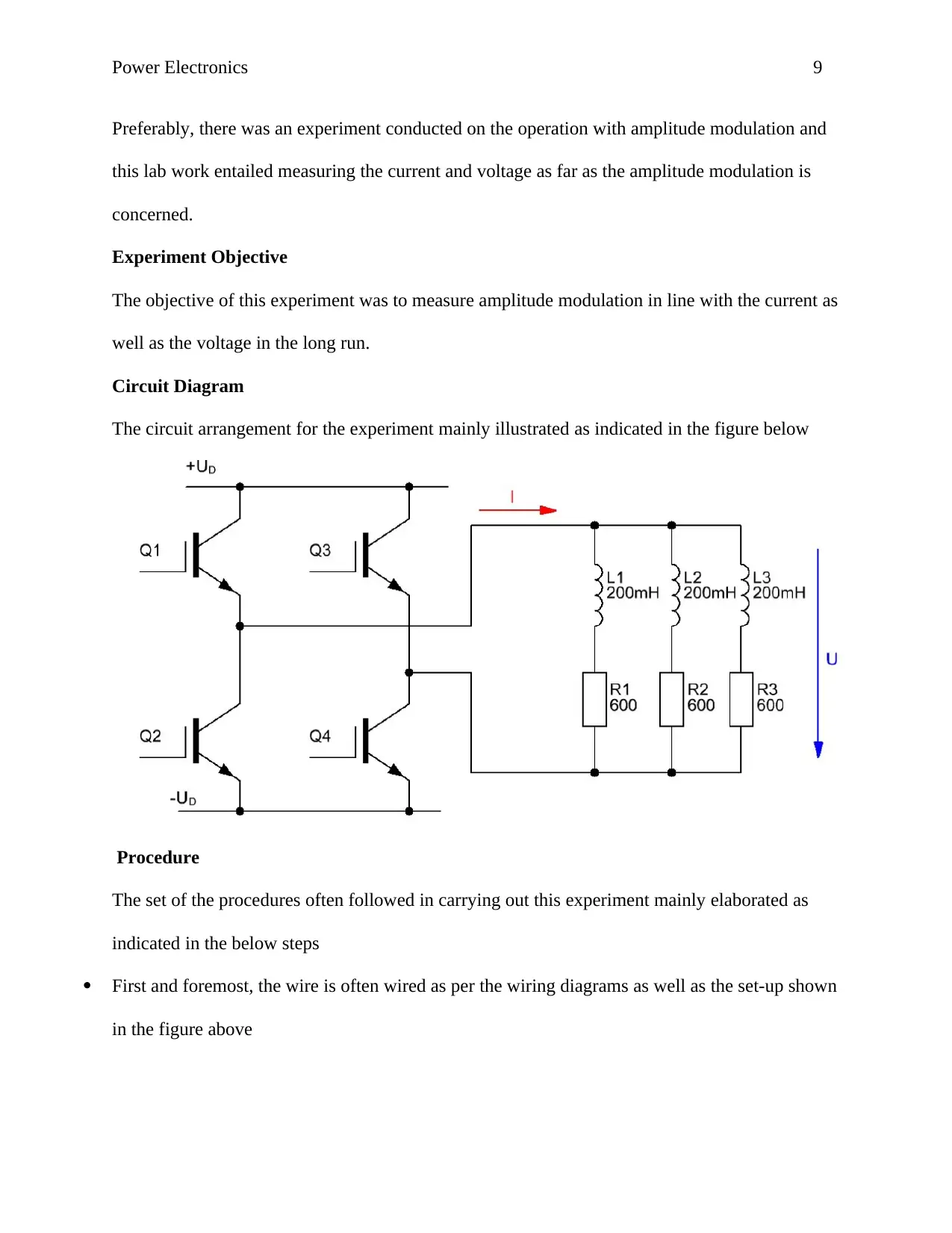
The circuit arrangement for the experiment mainly illustrated as indicated in the figure below
Procedure
The set of the procedures often followed in carrying out this experiment mainly elaborated as
indicated in the below steps
First and foremost, the wire is often wired as per the wiring diagrams as well as the set-up shown
in the figure above
⊘ This is a preview!⊘
Do you want full access?
Subscribe today to unlock all pages.

Trusted by 1+ million students worldwide
Power Electronics 10
Second, it is important to turn on the overall self-commutated converter and this is denoted as the
circuitry CO3636-3B
The third step involve turning on the transformer and this has to be done in line with the motor
protection switch
Furthermore, it is essential to open the alternating current as per the evaluation of the AC
Converter instrument
Notably, it is important to check and troubleshoot any problem which may occur in the
instrument. This analysis must be carried out as per the guidelines outlined in the software help.
Subsequently, the performance of the overall settings in line with the specified characteristics
mainly noted and demarcated as indicated in the table below
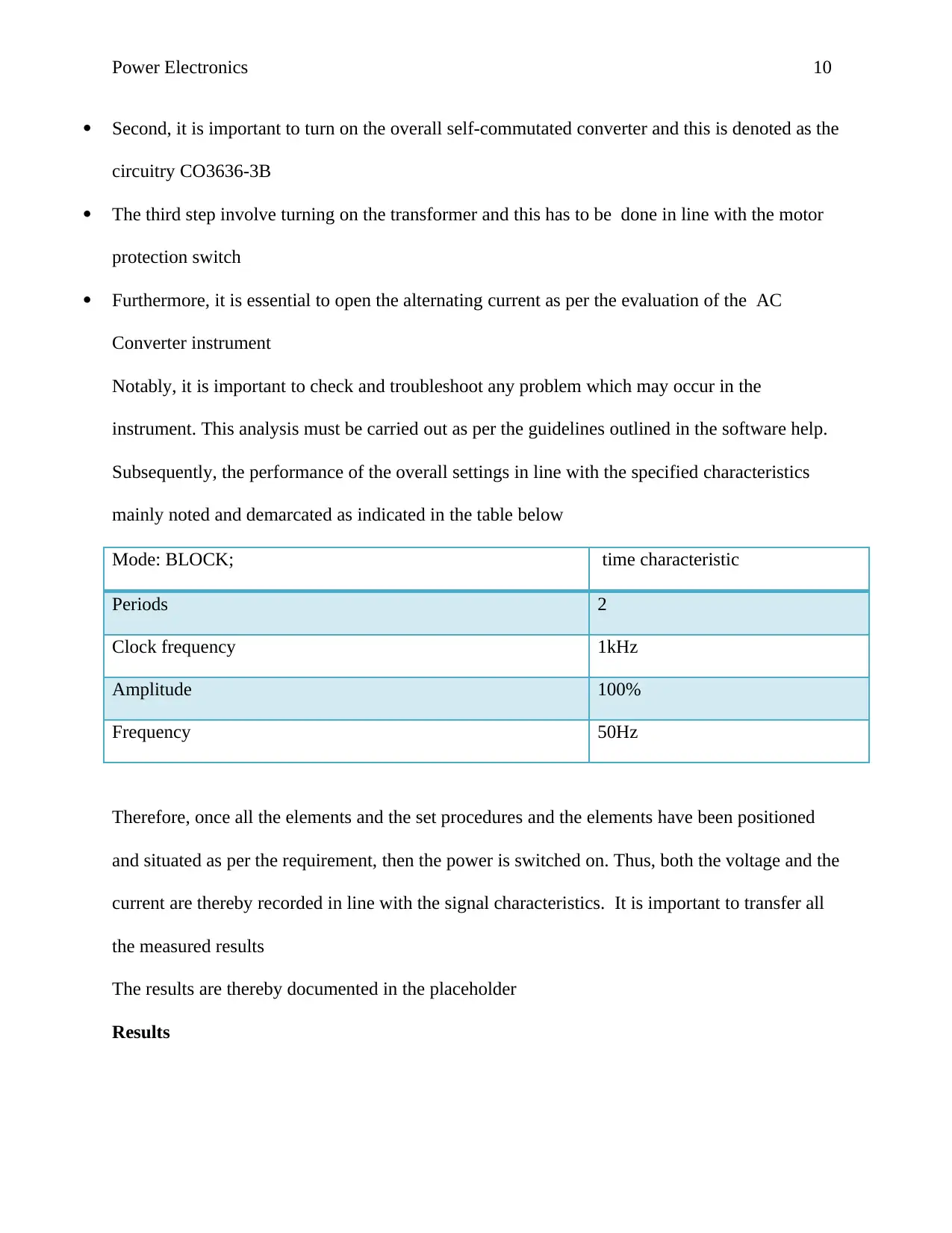
Mode: BLOCK; time characteristic
Periods 2
Clock frequency 1kHz
Amplitude 100%
Frequency 50Hz
Therefore, once all the elements and the set procedures and the elements have been positioned
and situated as per the requirement, then the power is switched on. Thus, both the voltage and the
current are thereby recorded in line with the signal characteristics. It is important to transfer all
the measured results
The results are thereby documented in the placeholder
Results
Paraphrase This Document
Need a fresh take? Get an instant paraphrase of this document with our AI Paraphraser
Power Electronics 11
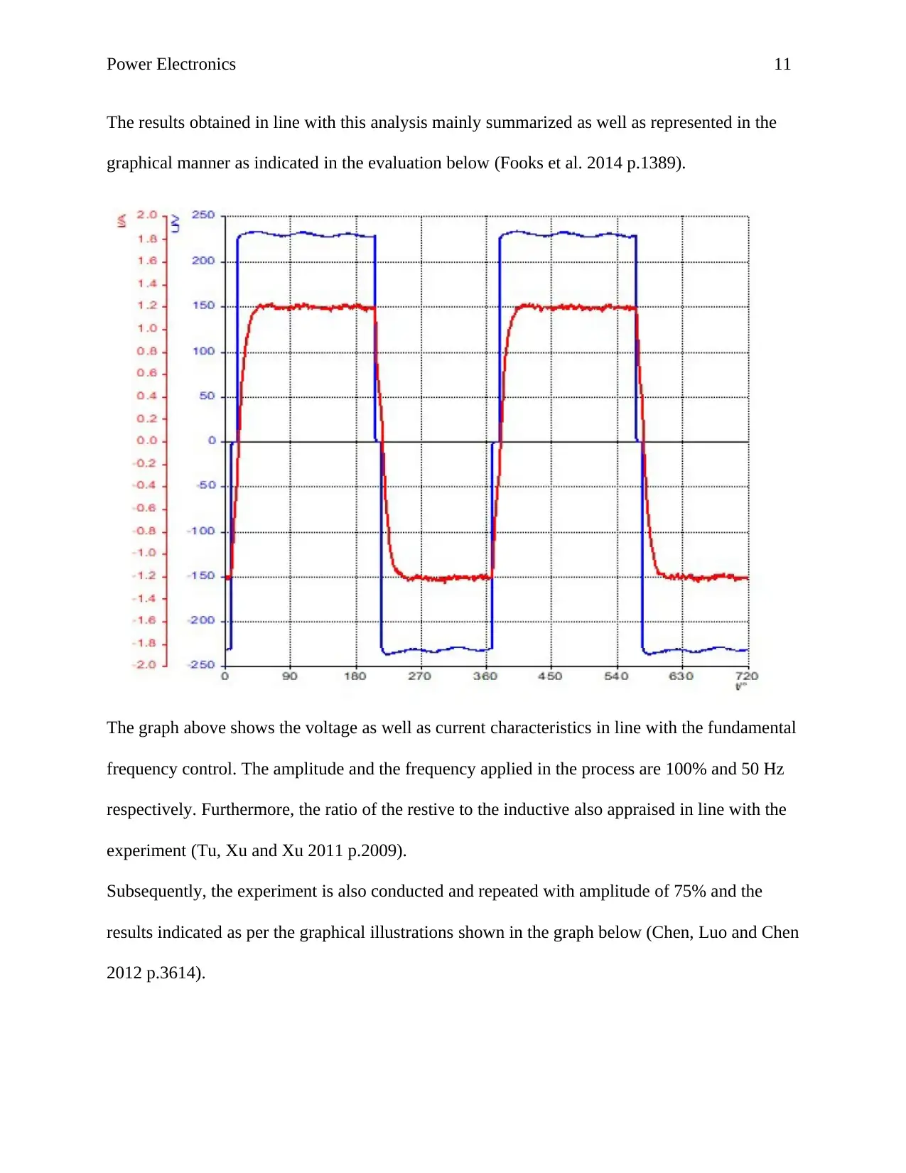
The results obtained in line with this analysis mainly summarized as well as represented in the
graphical manner as indicated in the evaluation below (Fooks et al. 2014 p.1389).
The graph above shows the voltage as well as current characteristics in line with the fundamental
frequency control. The amplitude and the frequency applied in the process are 100% and 50 Hz
respectively. Furthermore, the ratio of the restive to the inductive also appraised in line with the
experiment (Tu, Xu and Xu 2011 p.2009).
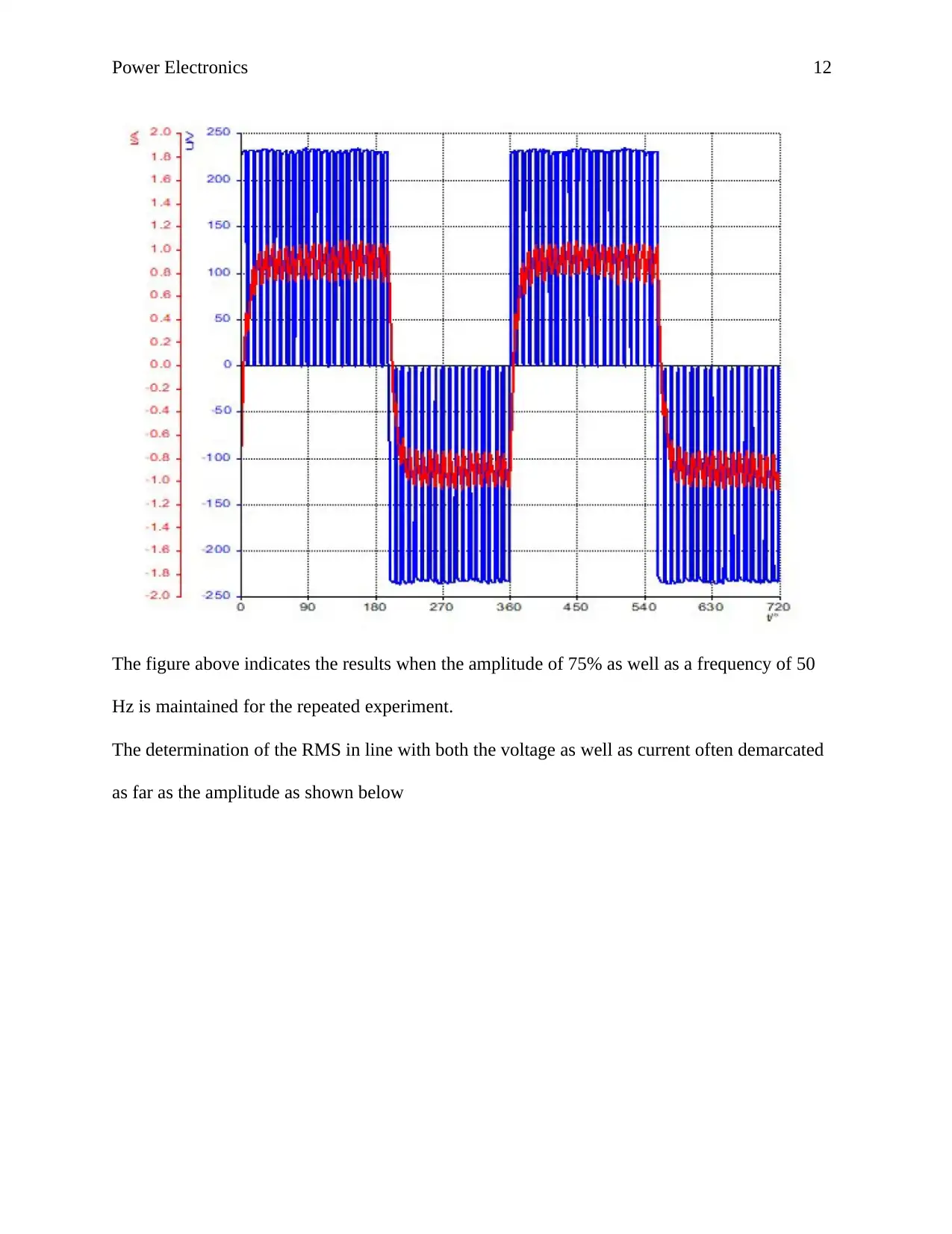
Subsequently, the experiment is also conducted and repeated with amplitude of 75% and the
results indicated as per the graphical illustrations shown in the graph below (Chen, Luo and Chen
2012 p.3614).
Power Electronics 12
The figure above indicates the results when the amplitude of 75% as well as a frequency of 50
Hz is maintained for the repeated experiment.
The determination of the RMS in line with both the voltage as well as current often demarcated
as far as the amplitude as shown below
The figure above indicates the results when the amplitude of 75% as well as a frequency of 50
Hz is maintained for the repeated experiment.
The determination of the RMS in line with both the voltage as well as current often demarcated
as far as the amplitude as shown below
⊘ This is a preview!⊘
Do you want full access?
Subscribe today to unlock all pages.

Trusted by 1+ million students worldwide
1 out of 30
Related Documents
Your All-in-One AI-Powered Toolkit for Academic Success.
+13062052269
info@desklib.com
Available 24*7 on WhatsApp / Email
![[object Object]](/_next/static/media/star-bottom.7253800d.svg)
Unlock your academic potential
Copyright © 2020–2026 A2Z Services. All Rights Reserved. Developed and managed by ZUCOL.


