Design and Fabrication of a DC to AC Inverter: A Project Report

Verified

Added on  2023/06/10

|7
|1623
|178
Project
AI Summary
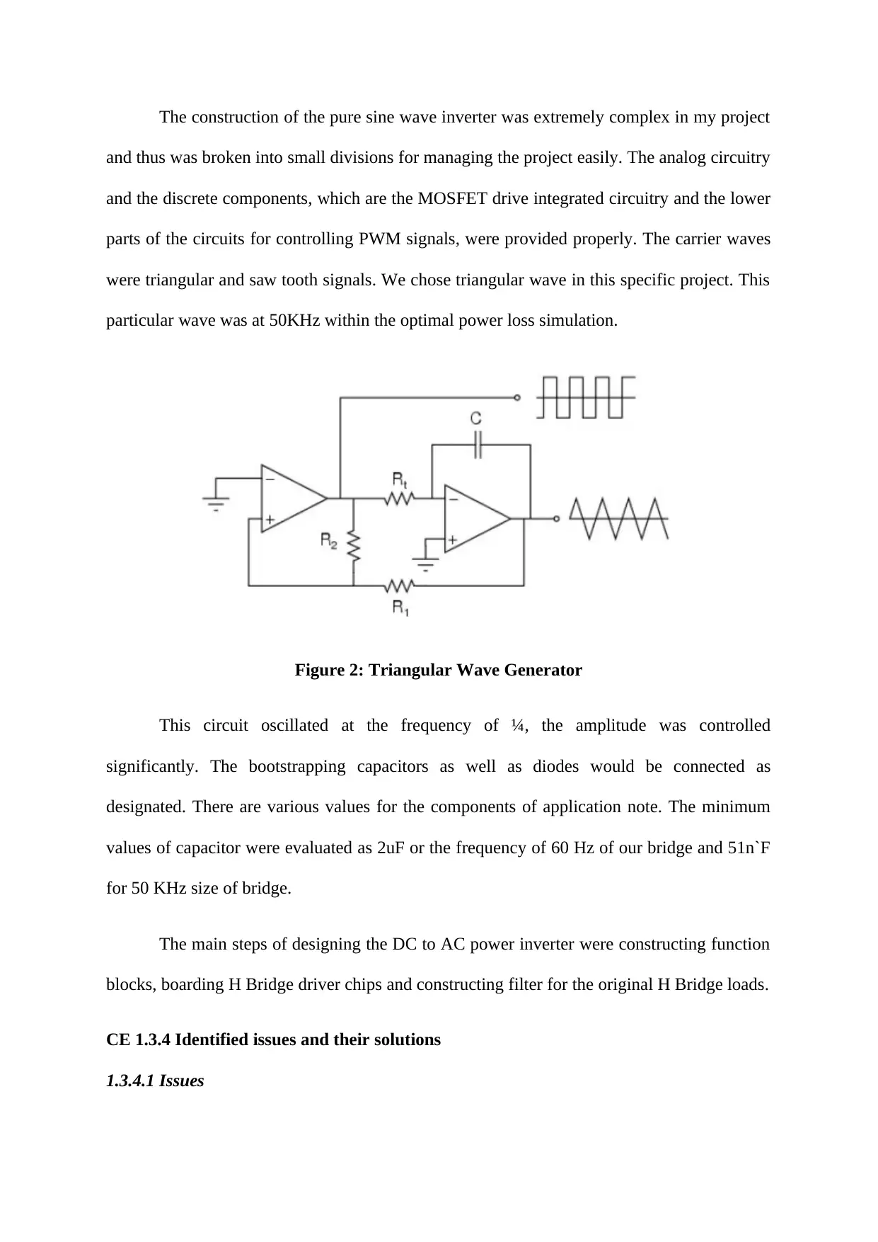
This document presents a project focused on the design and fabrication of a DC to AC inverter, detailing the conversion of low DC power voltage to high AC source voltage. The project outlines objectives such as designing and fabricating the inverter, converting low DC voltage to high DC voltage, and addresses challenges encountered during the process. The project involved electrical maintenance, installation of new electrical equipment, and planning electrical installations. Key skills applied included circuit design, electrical measurements, and interpersonal communication. The report discusses the theory behind the project, including the use of pulse width modulation and analog components for producing a clean sinusoid output. Issues such as the broader range of BM2P Series and oscillation frequency of converter voltages were identified and solutions proposed. The team planned to produce creative and innovative work by segregating responsibilities effectively.
tabler-icon-diamond-filled.svg

Contribute Materials

Your contribution can guide someone’s learning journey. Share your documents today.
Document Page
CE 1.1 Project Information
Name of the project: Design and Fabrication of DC to AC Inverter
Location of the project: Please fill
Project Duration: Please fill
Organization: Please fill
Role and Designation during the time: Team Member of the project
CE 1.2 Project Background
CE 1.2.1 Characteristics of the project
The project of Design and Fabrication of DC to AC Inverter mainly focuses on the
efficient transformation of a DC power source to the higher voltage source of AC. the
inverters are utilized for all types of applications and lower voltage DC sources like fuel cells,
solar panels and batteries, which is to be converted for the purpose of devices running off to
the AC power. The methodology, where lower voltage DC power to the higher voltage source
of DC, was eventually completed in two steps. A specific transformer was utilized for
boosting the voltage to 120 volts. We focused on the conversion of low voltage power of DC
to higher voltage source of DC.
CE 1.2.2 Objectives developed for the project
The project of Design and Fabrication of DC to AC Inverter consists of several
objectives. They are as follows:
To design and fabricate DC to AC inverter.
To convert low DC power voltage to high DC source voltage.
tabler-icon-diamond-filled.svg

Secure Best Marks with AI Grader

Need help grading? Try our AI Grader for instant feedback on your assignments.
Document Page
CE 1.2.3 My area of work
My major area of work was to convert the low DC power voltage to high DC source
voltage. I had to follow standard operating procedures for the purpose of repairing electrical
systems. My other area of work was participating in the advancement as well as usage of the
computerized maintenance management system. I even performed high voltage switching and
operated generators in support of the operations at transmission plant. I took up the research
part and documented the entire project report.
CE 1.2.4 Project Group
Figure 1: People involved in the project
CE 1.2.5 My responsibilities throughout the project
I had various important responsibilities in this project. My first and the foremost
responsibility in this particular project was to perform electrical maintenance works,
whenever needed after including necessary repairs to the high line MEP infrastructure as well
as utilities. My next responsibility was to install, alter, maintain and finally repair the
electrical wiring systems or equipments, both in the higher and lower voltages. I completed
Document Page
the installation of all the new electrical and electronic equipments as per the indication of
Transmission Company of Nigeria. I even planned for electrical installations for the
minimization of waste of materials and provided access for the future maintenance. My other
responsibilities were preparing and presenting sketches for showing the location of
equipments and wiring. I was happy to execute all the responsibilities and duties effectively
and efficiently.
CE 1.3 Distinctive Activity
CE 1.3.1 Engineering knowledge and skills applied in the project
Several electrical engineering skills and knowledge were applied in this particular
project by me. The first important skill that I have applied here is the designing of circuits. I
have a deep understanding of working procedure of circuits and even how to fix or design
them eventually. The instrumentation as well as electrical measurements was the next skill
applied by me in the project. I can also test the electric currents and the different components
reacting with one another. The interpersonal communication skill was yet another significant
skill required in this project of Design and Fabrication of DC to AC Inverter. I have even
used various programming languages for solving the equations and designing the circuits.
CE 1.3.3 Comprehending the Theory of Project
This project of Design and Fabrication of DC to AC Inverter focus in efficiently
transforming the DC power to the high voltage AC source. This is same as the power, which
is available at the outlet of electrical wall. I have used the methodology of converting lower
voltage DC power to the higher voltage source of DC. The pure sine wave inverters are
responsible for producing sine wave outputs. These outputs are identical to the specific power
coming from the electrical outlet. The AC power subsequently diminishes the audible noise
Document Page
within the devices like fluorescent lights or running inductive loads like motors, which are
much faster or even quieter for lower harmonic distortion.
Our major goal was filling the niche for lacking within the power inverters. With the
help of pulse width modulation as well as analog components, the output was a clean sinusoid
and had extremely less noise. The power inverters are typical devices that have the ability for
converting DC energy to AC electrical energy. The major purpose of the inverter of DC to
AC power has eventually taken the power of DC directly that is being supplied by the battery,
and finally transforming this voltage to the 120 volt source of AC power, which is working at
the frequency of 60 Hz.
The inverters in our project eventually allowed us in providing AC power within
several areas in which only the batteries are available and hence enabling the portability. All
of the inverters in this project differ in the outputs, hence providing several levels of
distortion and efficiency. The specific modified inverter of sine wave is responsible for
providing the cheapest as well as easiest solution to power devices, which require AC power.
There are some of the major drawbacks that every device does not work perfectly on any of
the modified sine wave. The several products like medical equipments as well as computers
are not at all resistant to signal distortion and hence should be run off a typical power source
of pure sine wave.
The switches that are utilized for implementing the H Bridge could be mechanical and
even built from the several solid state transistors. The utilization of P Channel MOSFET over
higher side and N Channel MOSFET over the lower side is much easier. The difficulty
should be overcome by the driver circuits and thus having the capability of charging external
capacitor for creating additional potential.
tabler-icon-diamond-filled.svg

Secure Best Marks with AI Grader

Need help grading? Try our AI Grader for instant feedback on your assignments.
Document Page
The construction of the pure sine wave inverter was extremely complex in my project
and thus was broken into small divisions for managing the project easily. The analog circuitry
and the discrete components, which are the MOSFET drive integrated circuitry and the lower
parts of the circuits for controlling PWM signals, were provided properly. The carrier waves
were triangular and saw tooth signals. We chose triangular wave in this specific project. This
particular wave was at 50KHz within the optimal power loss simulation.
Figure 2: Triangular Wave Generator
This circuit oscillated at the frequency of ¼, the amplitude was controlled
significantly. The bootstrapping capacitors as well as diodes would be connected as
designated. There are various values for the components of application note. The minimum
values of capacitor were evaluated as 2uF or the frequency of 60 Hz of our bridge and 51n`F
for 50 KHz size of bridge.
The main steps of designing the DC to AC power inverter were constructing function
blocks, boarding H Bridge driver chips and constructing filter for the original H Bridge loads.
CE 1.3.4 Identified issues and their solutions
1.3.4.1 Issues
Document Page
There were some of the major issues related to this project that I have faced. The first
and the foremost issue that I have faced here was the broader range of BM2P Series. This
particular series comprise of 24 models, with the internal output power transistor as well as
the most protective functionalities. The second issue that I have faced here is oscillation
frequency of converter voltages within the time of computation. All of these frequencies
solely depend on the system impedance size. The size of capacitor was obtained from the
controllable AC or DC converter and was absolutely wrong in our project. We compared this
result with the respective simulation as well as theoretical results. These issues were to be
resolved as soon as possible. Hence, we focused on the solutions of all these problems.
1.3.4.2 Solutions
I suggested some of the most relevant and significant solutions to these problems that
we have faced in the project of Design and Fabrication of DC to AC Inverter. For the first
issue of broader range of BM2P Series, I provided the suggestion that the inverter should be
tripped and it is required for pressing the trip reset button over the device for resetting it. The
BM2P series had 24 models and hence I suggested that a proper series should be selected. For
the second significant issue of oscillation frequency of converter voltages in this particular
project, I gave the suggestion that harmonic oscillator is the system, which is when displaced
from the equilibrium position, solely experiences the restoring force, absolutely proportional
to displacement. For the next important issue of simulation of
CE 1.3.5 Plan to produce creative and innovative work
Our plan was to produce creative as well as innovative work by segregating our work
eventually. We made sure that all the team members are executing their duties or
responsibilities effectively and efficiently. This type of effective plan helped us in
Document Page
understanding our flaws and errors and hence was successful in removing all the problems in
this specific project.
chevron_up_icon
1 out of 7
circle_padding
hide_on_mobile
zoom_out_icon
logo.png

Your All-in-One AI-Powered Toolkit for Academic Success.

Available 24*7 on WhatsApp / Email

[object Object]