Control Systems and Power Electronics: DC Motor and Inverter Analysis
VerifiedAdded on 2022/09/07
|13
|903
|35
Homework Assignment
AI Summary
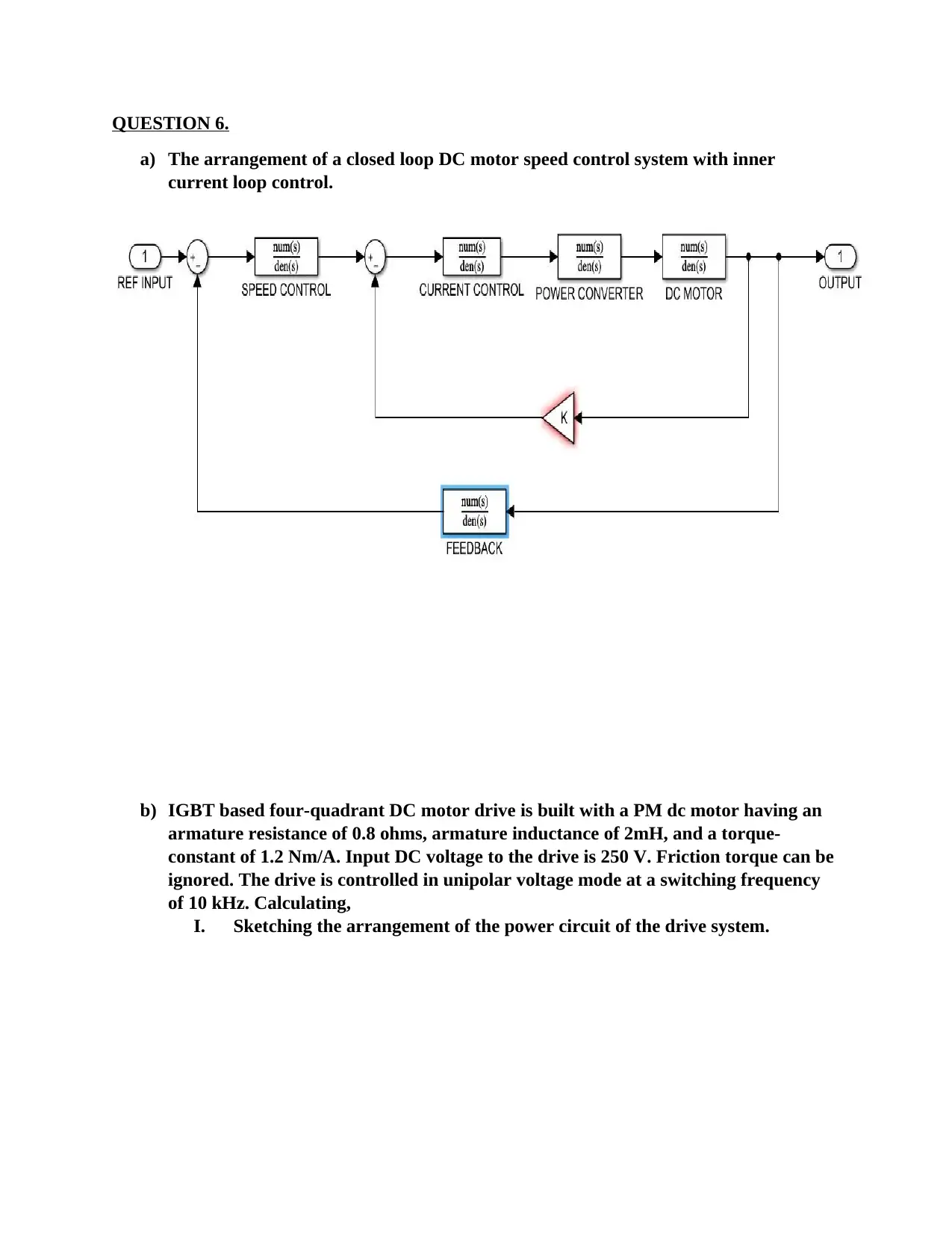
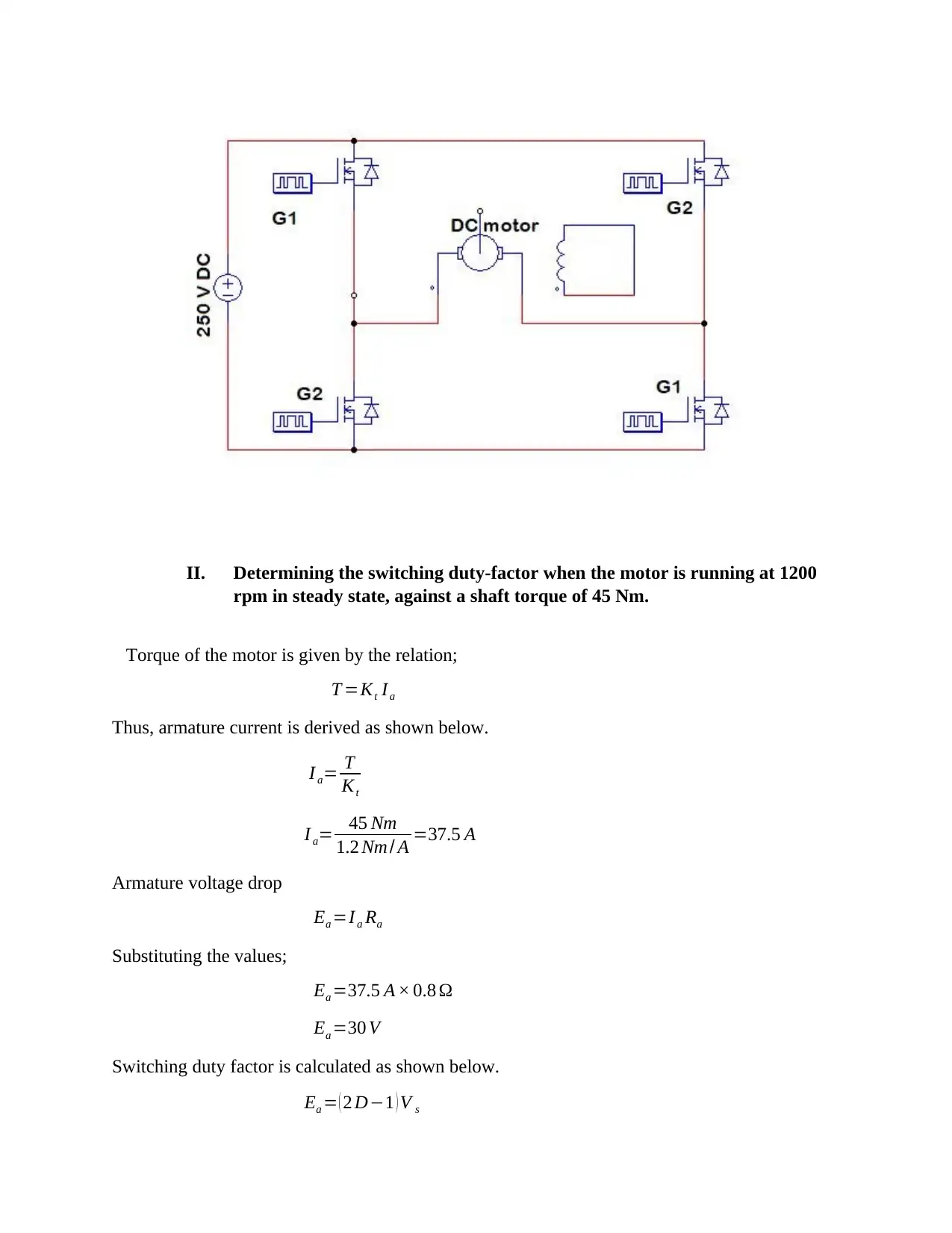
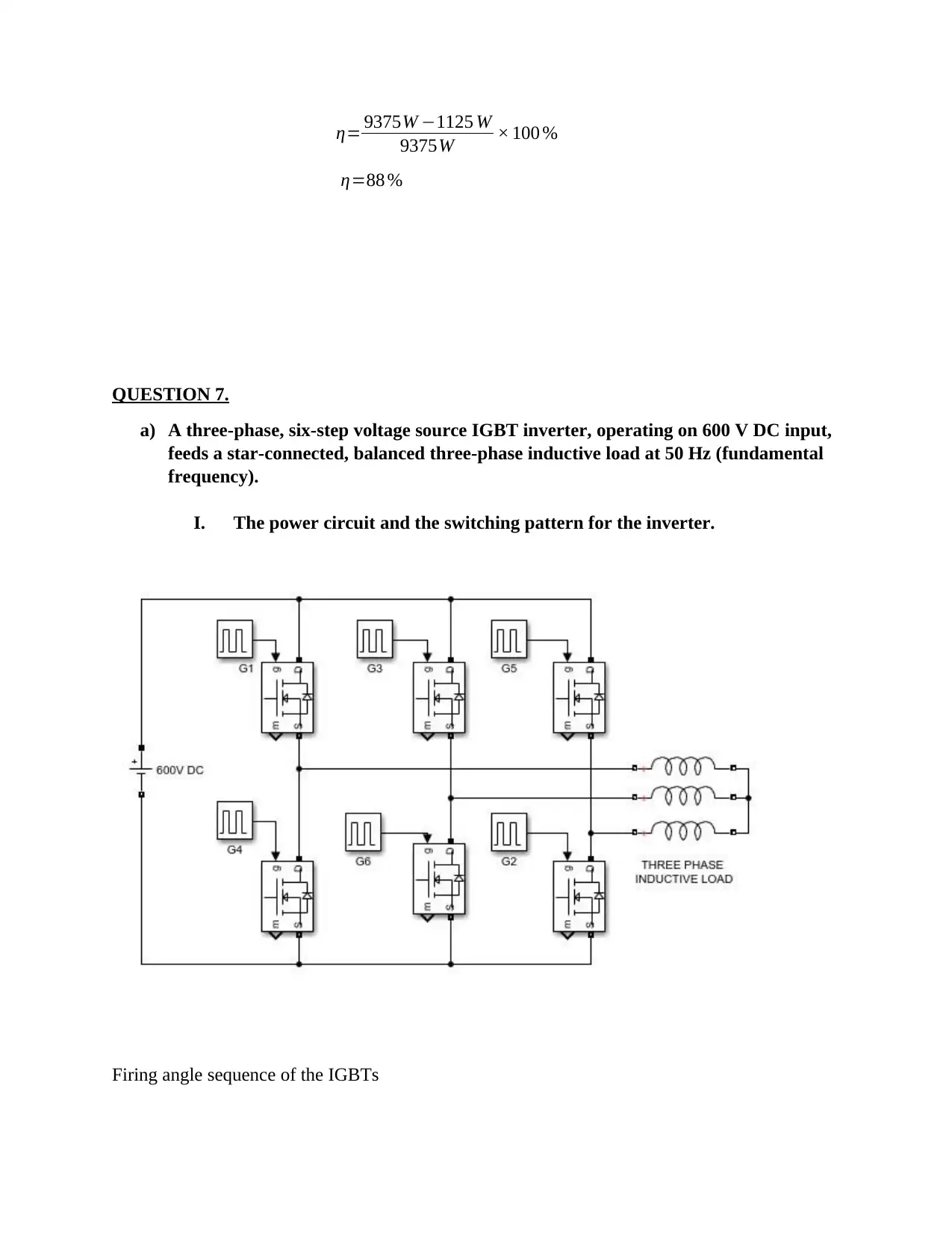
This homework assignment provides a detailed analysis of DC motor speed control systems, including the design of a four-quadrant DC motor drive with inner current loop control. It covers calculations for switching duty factor, armature current ripple, and motor efficiency. The assignment also includes an analysis of a three-phase, six-step voltage source IGBT inverter, determining RMS values of voltage and harmonics. Furthermore, it addresses a three-phase AC to DC diode converter and a three-phase induction motor variable speed drive, including slip regulation and speed ranges for constant-torque and constant-horsepower regions. The solutions involve power circuit arrangements, switching patterns, and calculations related to voltage, current, and frequency control in various electrical drive systems.
Contribute Materials
Your contribution can guide someone’s learning journey. Share your
documents today.

QUESTION 6.
a) The arrangement of a closed loop DC motor speed control system with inner
current loop control.
b) IGBT based four-quadrant DC motor drive is built with a PM dc motor having an
armature resistance of 0.8 ohms, armature inductance of 2mH, and a torque-
constant of 1.2 Nm/A. Input DC voltage to the drive is 250 V. Friction torque can be
ignored. The drive is controlled in unipolar voltage mode at a switching frequency
of 10 kHz. Calculating,
I. Sketching the arrangement of the power circuit of the drive system.
Secure Best Marks with AI Grader
Need help grading? Try our AI Grader for instant feedback on your assignments.

II. Determining the switching duty-factor when the motor is running at 1200
rpm in steady state, against a shaft torque of 45 Nm.
Torque of the motor is given by the relation;
T =Kt Ia
Thus, armature current is derived as shown below.
I a= T
Kt
I a= 45 Nm
1.2 Nm / A =37.5 A
Armature voltage drop
Ea =I a Ra
Substituting the values;
Ea =37.5 A × 0.8 Ω
Ea =30 V
Switching duty factor is calculated as shown below.
Ea = ( 2 D−1 ) V s

Where V s −¿is the source voltage.
Rearranging the equation algebraically to make D the subject;
Ea =2 D V s−V s
2 DV s=Ea +V s
Therefore, switching duty factor is
D= Ea+V s
2 V s
=30+ 250V
2 ×250 V
D=0.56
III. Finding the magnitude of the peak-peak ripple in the armature current
waveform.
One switching cycle duration is given by;
T = 1
f s
Where f s−¿is the switching frequency.
T = 1
10× 103
T =1 00 μ s
Thus, closing and opening duration for G1 is calculated as;
Closing;
T close=T × D
T close=100 μs ×0.56
T close=56 μs
Opening;
T open=100−56 μs
T open=44 μs
When G1 is closed, the potential difference across the armature inductance is;
V ind=V s−Ea

V ind=250−30 V
V ind=220 V
The volt-second accumulated by the inductance during ON state is;
V ( T ) =V ind × Tclose
V ( T ) =220 V × 56 ×10−6 ms
V ( T ) =12.32× 10⁻³ Vs
Ripple current is calculated as;
∆ I= V ( T )
La
Where La−¿is the armature inductance.
∆ I= 12.32× 10⁻³ Vs
2 ×10⁻³ H
Thus, ripple current is;
∆ I=6.16 A
IV. Finding the efficiency of the motor drive system.
Rated output power of the motor is given by;
Prated=V s I a
Substituting the values;
Prated =250 V ×37.5 A
Prated=9375 W
Power losses in the armature resistance;
Ploss=Ra I a
2
Substituting the values;
Ploss=0.8Ω× 37.52
Ploss=1125 W
Efficiency of the machine;
η= Prated−Ploss
Prated
×100 %
Replacing with the values;
Secure Best Marks with AI Grader
Need help grading? Try our AI Grader for instant feedback on your assignments.

η= 9375W −1125 W
9375W × 100 %
η=88 %
QUESTION 7.
a) A three-phase, six-step voltage source IGBT inverter, operating on 600 V DC input,
feeds a star-connected, balanced three-phase inductive load at 50 Hz (fundamental
frequency).
I. The power circuit and the switching pattern for the inverter.
Firing angle sequence of the IGBTs

G5 G6 G6 G1 G1 G2 G2 G3 G3 G4 G4 G5 G5 G6
-60 60 120 180 240 300 360 420
Conducting Conductin
g
Conducting Conductin
g
Conducting Conductin
g
Conducting
Firing G1 G2 G3 G4 G5 G6
II. Finding the RMS values of the fundamental component of line voltage at
the load.
Phase voltage in a six step operation is given by;
V an ( t ) = ∑
n=1,5,7
∞ 4 V DC
3 nπ {1+cos ( nπ
3 )sin (nωt ) }
For fundamental component, n=1
V an ( t ) = 4 V DC
3 π {1+cos ( π
3 )sin (ωt ) }
Where,
ω=2 πf
ω=2 π × 50 Hz
ω=100 π
And
t= 1
f
Substituting in the equation;
V an ( t ) = 4 V DC
3 π {1+cos ( π
3 )sin (2 π ) }
Inserting the values;

V an ( t ) = 4 ×600
3 π {1+cos ( π
3 )sin (2 π) }
V an ( t ) =254.6 V
RMS value;
V RMS=V an ( t )
√2
V RMS= 254.6V
√2
V RMS=180 V
III. Finding the RMS values and the frequencies of the 2 lowest order
harmonics present in the line voltage.
The second and third harmonics are found when n=5∧7
V RMS= ∑
n=,5,7
∞ 2 √ 2V DC
3 nπ {1+ cos ( nπ
3 ) sin (2 n π ) }
Thus at n=5
V RMS= 2 √ 2 V DC
15 π {1+cos ( 5 π
3 ) sin (10 π ) }
V RMS= 2 √2 ×600
15 π {1+cos (5 π
3 )sin (10 π ) }
V RMS=36 V
The frequency is
f 5=50 Hz ×5
f 5=25 0 Hz
For n=7
V RMS= 2 √2 ×600
21 π {1+cos (7 π
3 )sin (14 π) }
Paraphrase This Document
Need a fresh take? Get an instant paraphrase of this document with our AI Paraphraser

V RMS=25.7 V
The frequency is
f 5=50 Hz ×7
f 5=3 50 Hz
b) A three-phase full bridge AC to DC diode converter, operating on 400 V, 50 Hz,
three-phase AC input, delivers 10 kW of power to an inductive load at the output.
You may assume that the load current is continuous and ripple free.
Determining,
I. Mean value of output DC voltage.
V RMS=400 V
Peak to peak voltage is found as;
V P−P =V RMS × √ 2
V P−P =400 V × √ 2
V P−P =565.7 V
Phase voltage
V ∅ =V P−P
√3
Replacing the values;
V ∅ =565.7 V
√3
V ∅ =326.6V
The average DC voltage output is;
V DC= {3 √ 3
π }V ∅
V DC= { 3 √ 3
π } 326.6 V
V DC=540.19 V

II. Peak-peak ripple in output DC voltage.
The voltage relationship of the system is given by;
V RMS(Ripple )
2=V RMS
2−V DC
2
Where
V RMS=V ∅
√2
V RMS= 326.6V
√ 2
V RMS=230.94 V
Thus, the peak-peak ripple DC output voltage is;
V RMS(ripple)= √ 540.192 −230.94 V 2
V RMS(ripple)=488 V
III. RMS value of the fundamental component of line current at the input.
The current in the circuit can be found using;
I a= Power
V DC
Where
Power=10 kW
Thus,
I a= 10× 1 03 W
540.19V
I a=18.51 A
The fundamental component of line current input is given by;

I ¿= √6
π I a
Substituting the values;
I ¿= √6
π × 18.51 A
I ¿=14.4 A
QUESTION 8.
a) A 3-phase, 4-pole, 50 Hz, 400 V cage rotor induction motor is used in a variable
speed drive with 10% initial boosting. At rated voltage and frequency the motor-
load system runs at 1440 rpm. Load torque can be assumed as constant for all
speeds. Determining the voltage and frequency combination required to operate the
drive at 350 rpm.
The motor speed without initial boost.
Speed= 100
110 ×350 RPM
Speed=318.18 RPM
The frequency required is found by;
f r= P
120 ( nsync−nm )
Where;
nsync−¿Synchronous rated speed
nm −¿Motor speed.
P−¿Number of poles.
Therefore the frequency at which the motor is operating is given by;
f r= 4
120 ( 1440−318.18 ) Hz
f r=37.4 Hz
Since speed of the motor is directly proportional to the amount of voltage applied, the
voltage is determined as shown below.
V =400 V × 318.18 RMP
1440 RPM
Secure Best Marks with AI Grader
Need help grading? Try our AI Grader for instant feedback on your assignments.

V =88.38V
b) Drawing a block diagram of the arrangement of a closed loop 3-phase induction
motor variable speed drive incorporating slip regulation.
b) Drawing a block diagram of the arrangement of a closed loop 3-phase induction
motor variable speed drive incorporating slip regulation.

c) A 4 pole, 50 HZ, 3-phase cage rotor induction motor has full load slip of 4% and
pull out slip of 10%. Calculating the ranges of speed for the constant-torque,
constant horsepower and high-speed regions of operation. Assume 4 times rated
speed as the maximum allowable speed.
The synchronous speed of the induction motor is given by;
nsync=120 f e
P
Where f e−¿is the electrical frequency, 50 Hz.
P−¿Number of poles.
Therefore,
nsync=120 × 50
4 RPM
nsync=1500 RPM
The minimum motor speed occurring at pull out slip of 10 % is given by;
nm = ( 1−s ) nsync
nm = ( 1−0.1 ) 1500 RPM
nm =1350 RPM
Maximum speed occurring at full load slip of 4% is given by;
nm = ( 1−s ) nsync
nm = ( 1−0.04 ) 1500 RPM
nm =1440 RPM

Maximum allowable speed of the motor is 4 times the rated speed.
nmax=4 ×1350 RPM
nmax =5400 RPM
nmax=4 ×1350 RPM
nmax =5400 RPM
1 out of 13

Your All-in-One AI-Powered Toolkit for Academic Success.
+13062052269
info@desklib.com
Available 24*7 on WhatsApp / Email
Unlock your academic potential
© 2024 | Zucol Services PVT LTD | All rights reserved.