Project on DC Motor Speed Control Using Pulse Width Modulation

Verified

Added on  2023/06/12

|8
|1815
|465
Project
AI Summary
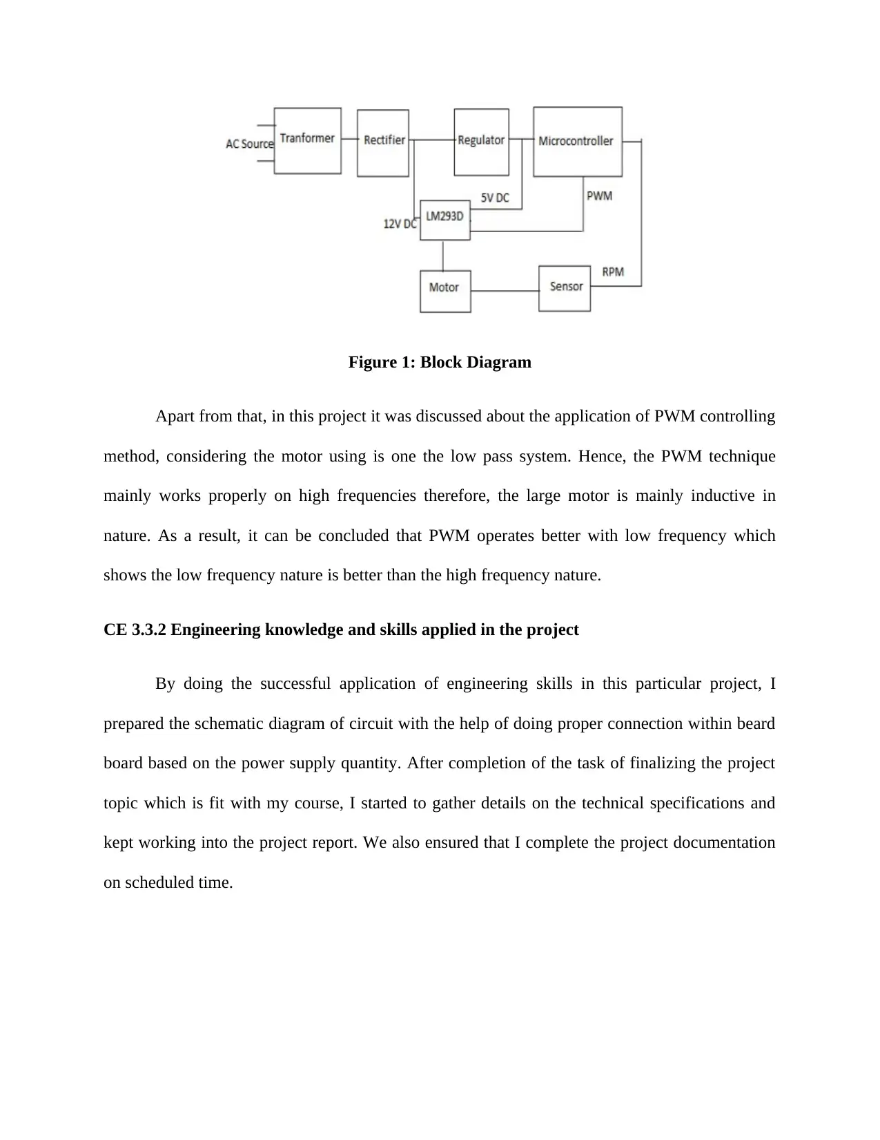
This project report details the implementation of Pulse Width Modulation (PWM) techniques for controlling the speed of DC motors. The project explores both electrical and mechanical methods for speed control, emphasizing the benefits of PWM for its low power loss in switching devices. An AT89S52 Microcontroller is used for power generation via PWM, where average power delivery is proportional to the modulation duty cycle. The project objectives include offering a simple and efficient control technique, operating the motor using pulse waves, designing hardware and software for speed control, and preparing a system for constant speed under varying loads. The contributor's role involved studying DC motors, justifying the use of PWM, and preparing the project thesis. Key activities included understanding the theory behind PWM, applying engineering skills to create schematic diagrams, identifying and solving issues related to power supply and energy wastage, and contributing to collaborative teamwork. The project reflects on the load characteristics and the use of PWM for modulating the DC motor based on IC and rectifier circuit characteristics.
Document Page
CE 3.1 Project Information
Name of the project: Speed controlling techniques of DC motors using Pulse Width
Modulation (PWM) technique
Location of the project: [PLEASE FILL]
Project Duration: [PLEASE FILL]
Organization: [PLEASE FILL]
Role and Designation during the time: Associate Electrical Engineer
CE 3.2 Project Background
CE 3.2.1 Characteristics of the project
This particular project mainly discussed about various speed controlling techniques of
any DC motors with the help of both electrical and mechanical techniques. For getting any
desirable outputs, the function of speed control in DC motors becomes more important.
Moreover, in this project, for the controlling of DC Motor speed, Pulse Width Modulation
(PWM) technique is used. It also get cleared from this paper that the accurate control of any
small DC motors can be done by not including any types of complicated and costly circuit.
However, different controlling strategies were implemented with the help of output speed error
technique along with its derivative termed as feedback damping signals. The main benefit of
using PWM for speed controlling was the low percentage of power loss occurred in switching
devices. In addition to all these, in this project, AT89S52 Microcontroller was implemented to do
the generation of power with the help of Pulse Width Modulation. The main principle works in
this project mentioned about average power delivery which gets directly proportional with
tabler-icon-diamond-filled.svg

Paraphrase This Document

Need a fresh take? Get an instant paraphrase of this document with our AI Paraphraser
Document Page
modulation duty cycle. Furthermore, due to high modulation rate, it becomes easy to smooth the
pulse train with the help of passive electronic filters and also facilitate to recover any average
type analogue waves.
CE 3.2.2 Objectives developed for the project
In terms of initiating this project successful and the proper implementation of different speed
controlling techniques of DC Motors, I have used Pulse Width Modulation (PWM) technique
because of its minimal power loss. However, below are some objectives that can set for the
appropriate implementation of this project is discussed below:
To offer a simple and efficient technique for the controlling of DC motors speed with the
help of Pulse Width Modulation (PWM) technique
To operate the motor using pulse wave, based on microcontroller and IC circuit
characteristics.
To do the better designing and proper implementation of both hardware and software for
doing speed control of DC Motor and the occurrence of any overload condition
To prepare a system used for DC Motor speed controlling depending on constant speed
with respect of load condition
To design and implement of a proper microcontroller based closed loop DC motor speed
controller which helps to operate the DC Motor’s speed with the help of DC chopper
along with PWM technique
To represent a signal depending on the output of motor speed controller for the reduction
of total load of current.
Document Page
CE 3.2.3 My area of work
As I was appointed as an associate electrical engineer and I was also just pass-out intern
in this project. I had only theoretical concept of electrical with no practical problems and
handling of different situation. Therefore, as an Intern, initially, I was asked to view the whole
project which helps to gain the in-depth knowledge regarding this project work. After initial
some days, I was assigned to study all types of available DC Motors and to select an appropriate
motor for this project. To select the required DC motor, I had used Flux Control Method,
Armature Voltage Control Method and the Armature Resistance Control based on difference in
field excitation along with the terminal voltage variation. In addition to DC motor selection, I
was asked for preparing the justification report of using PWM technique in this project which
was selected for its power adjusting technique based on 0% to 100% duty cycle. Apart from the
technical work, I was also asked to prepare detailed thesis report of the whole project along with
all specification and calculation work.
CE 3.2.4 Project Group
Document Page
CE 3.2.5 My responsibilities throughout the project
In the whole project work, the prime work undertaken by me was to check and
understand all areas of this particular project and to prepare a rough work of this. All the rough
work needed to be finalized by the project supervisor based on that the thesis paper will be done.
To write the thesis paper, I was also needed to do all types of calculation regarding IR sensor,
preparation of block diagram, proper understanding of the scope of this study. In addition to this,
I also undergone with different available methodologies related to this project work and based on
the pre-determined parameters of, I have selected the implementation of AT89S52
microcontroller using closed loop DC motor speed controller. Apart from all these, I also
performed different team building work and team recreation work under the supervisor guidance
that helps to create a team bonding and proper atmosphere to work within a team.
CE 3.3 Distinctive Activity
CE 3.3.1 Comprehending the theory of the project
Based on the theory of Electric Current, it discussed about the process of using Pulse
Width Modulation (PWM) technique that helps to control the speed of motors. For the
generation of pulse wave form in this project, the variable-voltage Dc power source is used. To
understand the whole process flow in this project, I prepared a block diagram which represents
the whole project structure:
tabler-icon-diamond-filled.svg

Paraphrase This Document

Need a fresh take? Get an instant paraphrase of this document with our AI Paraphraser
Document Page
Figure 1: Block Diagram
Apart from that, in this project it was discussed about the application of PWM controlling
method, considering the motor using is one the low pass system. Hence, the PWM technique
mainly works properly on high frequencies therefore, the large motor is mainly inductive in
nature. As a result, it can be concluded that PWM operates better with low frequency which
shows the low frequency nature is better than the high frequency nature.
CE 3.3.2 Engineering knowledge and skills applied in the project
By doing the successful application of engineering skills in this particular project, I
prepared the schematic diagram of circuit with the help of doing proper connection within beard
board based on the power supply quantity. After completion of the task of finalizing the project
topic which is fit with my course, I started to gather details on the technical specifications and
kept working into the project report. We also ensured that I complete the project documentation
on scheduled time.
Document Page
CE 3.3.3 Accomplishment and task performed
I realized based on the study that selection of proper DC motor is most critical task. I had
started the analysis of the DC motor and found that series would motor controlled with the PWM
technique. In this case, duration of pulse is main factor to control speed. I realized that
characteristics of DC motor such as torque and speed as critical characteristics to be taken into
my considerations.
Figure 2: Armature of DC permanent magnet motor
CE 3.3.4 Identified issues and their solutions
To continue this project work, I along with all team members faced two serious technical
challenges which are discussed below:
a. Due to the constant power supply to any device is wasteful because of energy wasted at
times of using resistor to limit the current flow passed to the attached motor. In addition, if the
load quantity changed during the uses of resistor, the quantity of current used by that particular
Document Page
device will get re-distributed above new created load. Due to the whole process, it requires
constant adjustment of resistor in circuit which is not ideal for any project. As the energy
consumption of any resistor is based on the motor size.
b. Apart from that, according to the above mentioned issue, at times of turning motor it
needs less energy for the maintenance of this spinning resulting of the wastage of extra supplied
energy.
The implemented solutions in this project based on above mentioned problems are mainly
based on using of Pulse Width Modulation (PWM) technique. Moreover, with the successful
implementation of PWM technique, it provides the way to modulate both on/off time of power
supply. It also allows us to supply full voltage to any motor at initial starting. It will also get the
motor will be sufficient with power which kept the motor in full spin rather than getting dead
stop end.
CE 3.3.5 Plan to produce creative and innovative work
In order to create this particular project, it discussed about the creation of DC Motors
using different speed controlling techniques. Regarding this project innovative work, it also
discussed about the types of IR sensors, IC, LCD display which are used to create the motor
driving pin and the rectifier schematic. Apart from that, with the help of used 555 IC, along with
the pulse width modulation, all pulse generation, pulse position modulation, precision timing and
sequential timing process are done to get the successful result of the whole project work.
CE 3.3.6 Collaborative work
This particular project also reflects the good example of a collaborative work done in this
project. As I was new in the system, I was needed to get the proper guidance in every step of this
tabler-icon-diamond-filled.svg

Paraphrase This Document

Need a fresh take? Get an instant paraphrase of this document with our AI Paraphraser
Document Page
project work. During site visit, I roamed in the whole areas of functional module and if needed I
also communicate with the project supervisor and note the down all points that was needed to
discuss all these with the concerned supervisor.
CE 3.4 Project Review
3.4.1 Project Overview
This particular project discussed about the load characteristics as well as speed
controlling technique based on DC motor. Another important point discussed in this project is
PWM technique which is used to do the modulating of the DC motor depending on the
characteristics of IC and rectifier circuit.
3.4.2 My contribution
I was assigned as an Intern Associate in this particular project and I successfully
accomplished all works which leads the proper implementation of whole project. I also prepared
the block diagram of whole project based on the scope study. Apart from that, I also studied the
power supply output after doing the testing of CRO set with respect to the per-determined
verified results.
chevron_up_icon
1 out of 8
circle_padding
hide_on_mobile
zoom_out_icon
[object Object]