D.C. Power Supplies: Analysis, Design & Simulation in Digital Circuits

Verified

Added on  2022/09/08

|14
|1135
|17
Homework Assignment
AI Summary
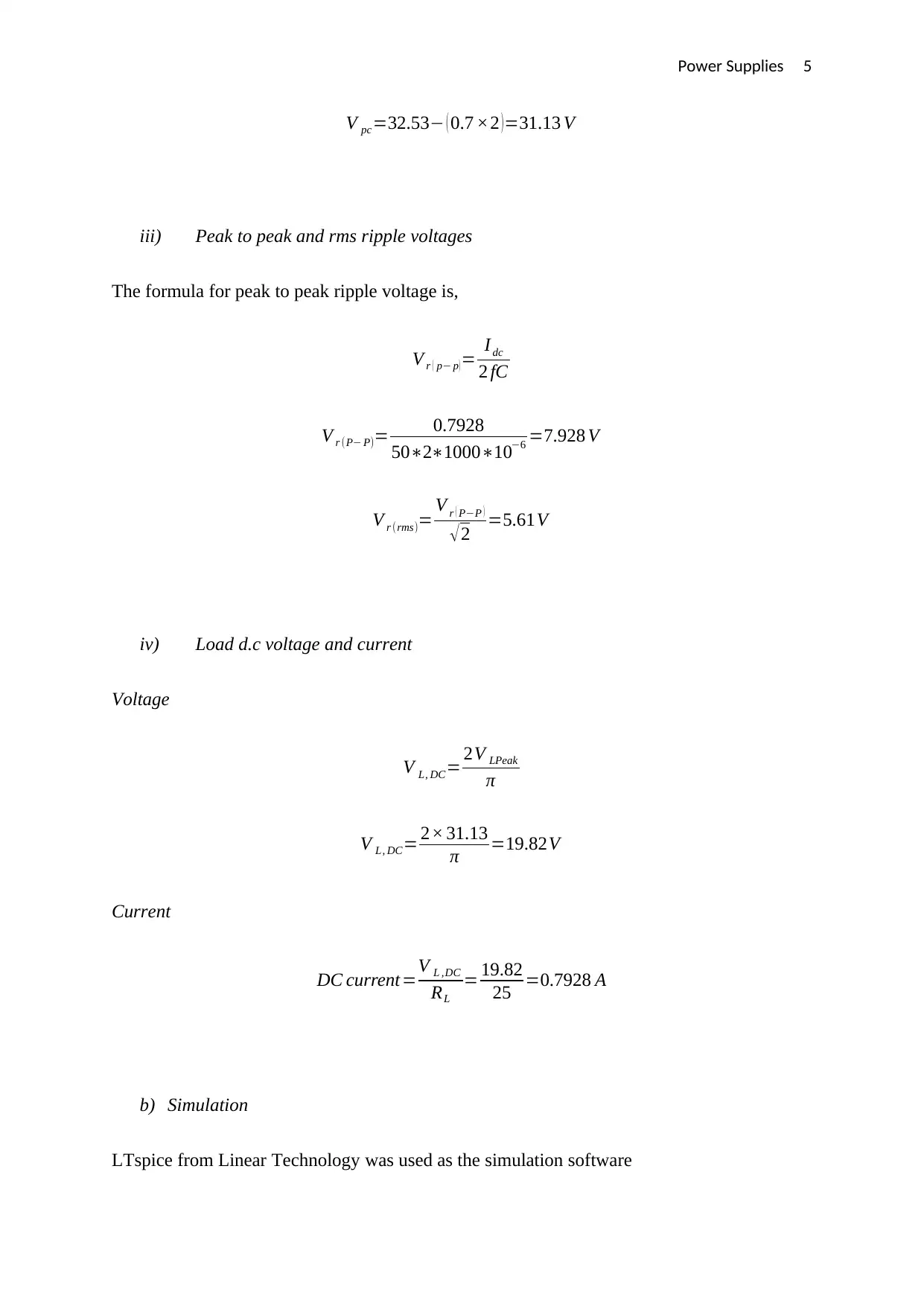
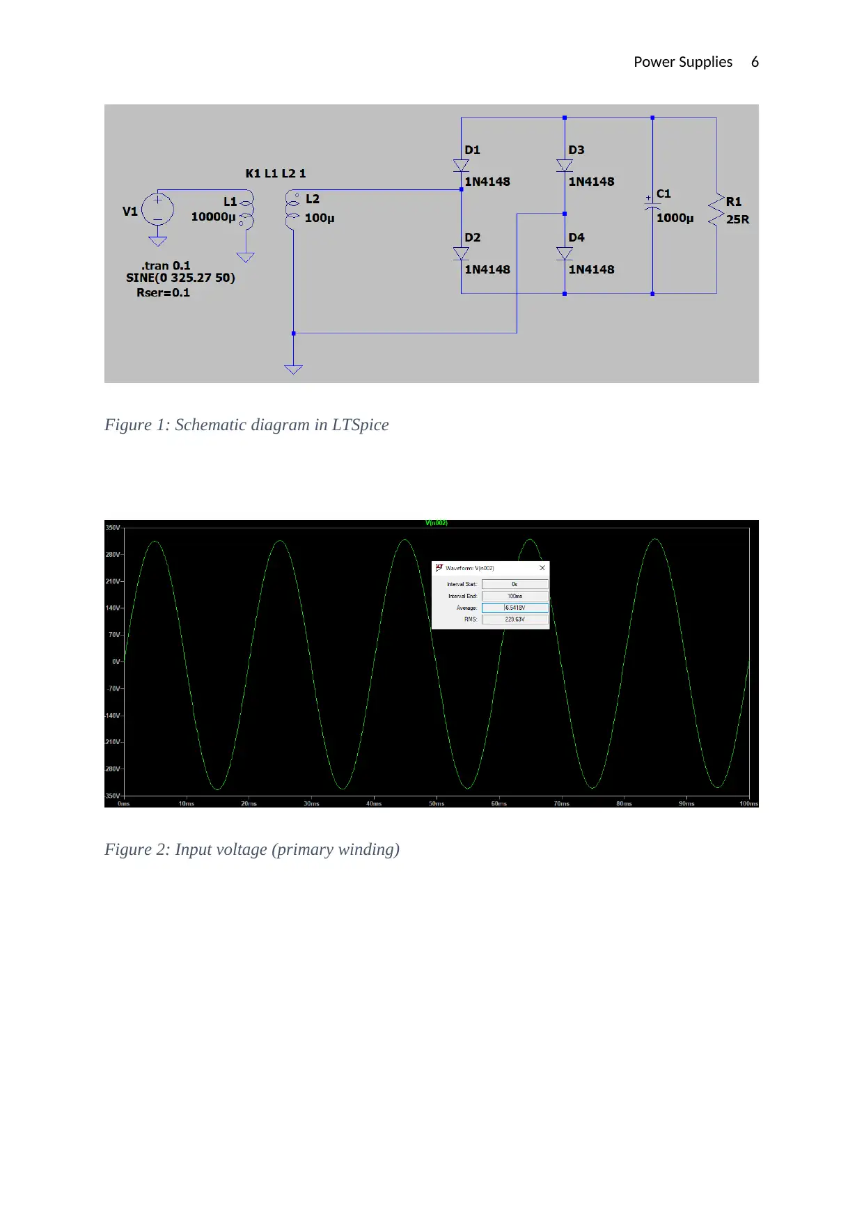
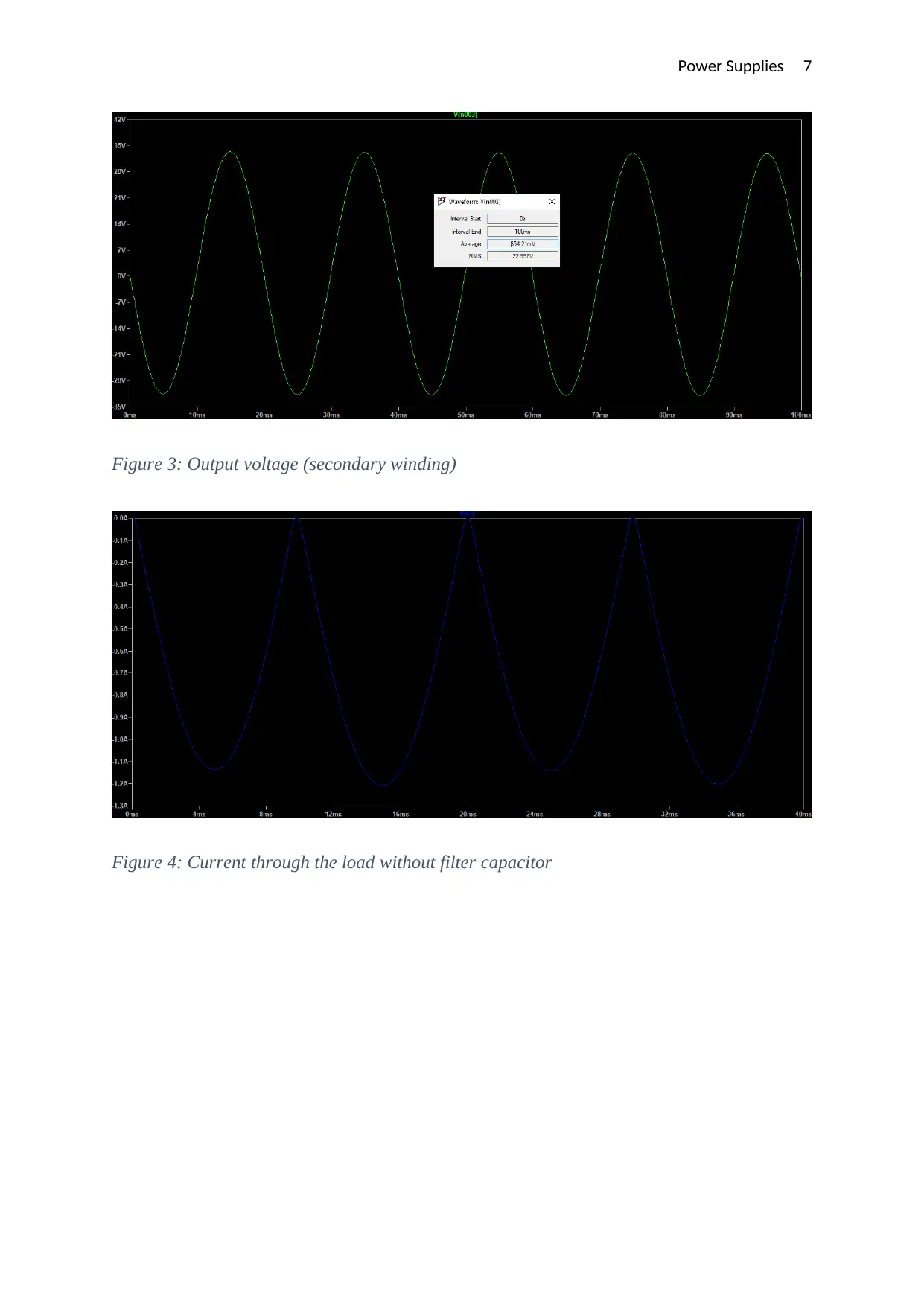
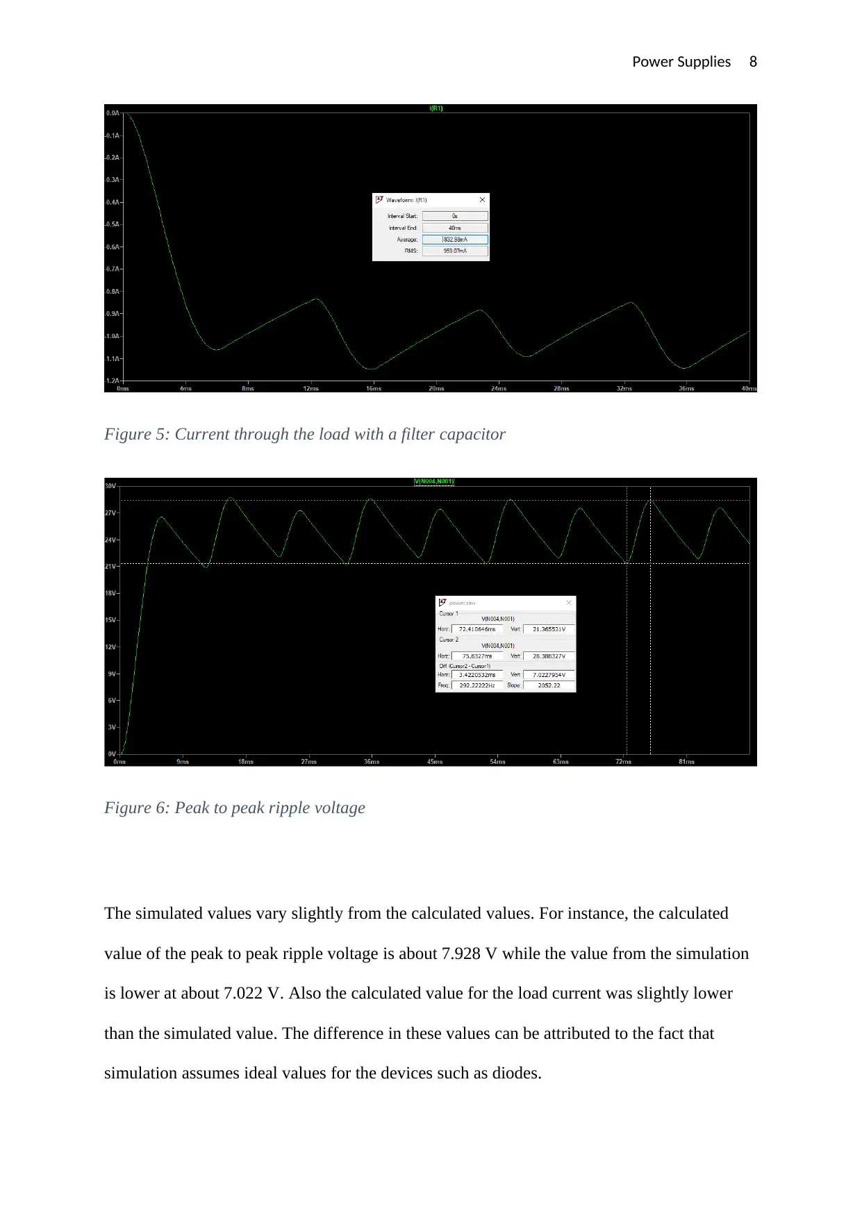
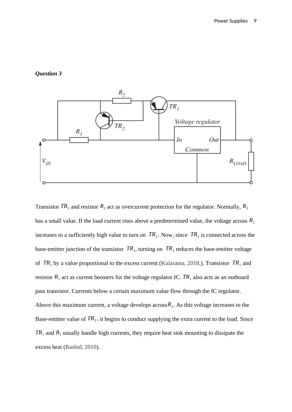
This assignment provides solutions related to D.C. power supplies, covering topics such as rectifier circuit operation, ripple voltage calculation, and the role of filter capacitors. It includes a detailed analysis of a bridge rectifier circuit, with calculations for peak voltage, ripple voltage, and load current, supplemented by LTspice simulations to validate the results. The assignment also discusses overcurrent protection mechanisms using transistors and resistors, as well as the advantages and disadvantages of switch-mode power supplies compared to linear regulated supplies. The final question focuses on designing a regulated power supply, considering input voltage requirements, diode voltage drops, and transformer turns ratio, while also addressing heat dissipation considerations for IC regulators. Desklib offers a wide range of study resources, including past papers and solved assignments, to support students in their academic endeavors.
Document Page
Power Supplies 1
MODULE TITLE: DIGITAL & ANALOGUE DEVICES & CIRCUITS
TOPIC TITLE: D.C. POWER SUPPLIES’
Student’s Name
Professor’s Name
Date
tabler-icon-diamond-filled.svg

Paraphrase This Document

Need a fresh take? Get an instant paraphrase of this document with our AI Paraphraser
Document Page
Power Supplies 2
Question 1
a) Sketches
Document Page
Power Supplies 3
b) Operation of the circuit
During the positive half cycle, the diodes D1 and D3 are active. The current therefore flows
throughD1, through the load and through D3 back to the supply. The total voltage drop across
the diodes is equivalent to twice that of a single diode. For silicon diodes, this would be about
1.4 volts. During the positive half-cycle, D2 and D4 are not conducting hence the voltage
drop across them is zero. During the negative half-cycle, D1 and D3 are off while D4 and D2
Document Page
Power Supplies 4
conduct in that order. The current flows throughD4, the load and finally through D2 back to
the source. The total voltage drop is the same as for that during the positive half-cycle. The
DC smoothing capacitor charges when current is flowing in either of the two half-cycles. The
energy stored by the capacitor is then fed into the load when the output voltage of the rectifier
falls below that of the capacitor during the cycle. This makes the DC output smoother.
Question 2
a)
Given that,
supply voltage ,V s=230 V rms
frequency , f =50 Hz
load RL=25 Ω
Capacitance , C=1000 μF
Transformer turns ratio=10 :1
i) Rms and peak voltage across transformer secondary winding
rms voltage ,V rms=230
10 =23 V
peak voltage= 2V rms
peak voltage , V p= 2 ×23=32.53 V
ii) Peak voltage across the capacitor
Assuming a drop of 0.7 V per diode,
tabler-icon-diamond-filled.svg

Paraphrase This Document

Need a fresh take? Get an instant paraphrase of this document with our AI Paraphraser
Document Page
Power Supplies 5
V pc=32.53 ( 0.7 ×2 )=31.13 V
iii) Peak to peak and rms ripple voltages
The formula for peak to peak ripple voltage is,
V r ( p p )= I dc
2 fC
V r (P P)= 0.7928
5021000106 =7.928 V
V r (rms)= V r ( PP )
2 =5.61V
iv) Load d.c voltage and current
Voltage
V L, DC= 2V LPeak
π
V L, DC= 2× 31.13
π =19.82V
Current
DC current=V L ,DC
RL
= 19.82
25 =0.7928 A
b) Simulation
LTspice from Linear Technology was used as the simulation software
Document Page
Power Supplies 6
Figure 1: Schematic diagram in LTSpice
Figure 2: Input voltage (primary winding)
Document Page
Power Supplies 7
Figure 3: Output voltage (secondary winding)
Figure 4: Current through the load without filter capacitor
tabler-icon-diamond-filled.svg

Paraphrase This Document

Need a fresh take? Get an instant paraphrase of this document with our AI Paraphraser
Document Page
Power Supplies 8
Figure 5: Current through the load with a filter capacitor
Figure 6: Peak to peak ripple voltage
The simulated values vary slightly from the calculated values. For instance, the calculated
value of the peak to peak ripple voltage is about 7.928 V while the value from the simulation
is lower at about 7.022 V. Also the calculated value for the load current was slightly lower
than the simulated value. The difference in these values can be attributed to the fact that
simulation assumes ideal values for the devices such as diodes.
Document Page
Power Supplies 9
Question 3
Transistor TR2 and resistor R2 act as overcurrent protection for the regulator. Normally, R2
has a small value. If the load current rises above a predetermined value, the voltage across R2
increases to a sufficiently high value to turn on TR2 . Now, since TR2 is connected across the
base-emitter junction of the transistor TR1, turning on TR2 reduces the base-emitter voltage
of TR1 by a value proportional to the excess current (Kularatna, 2018,). Transistor TR1 and
resistor R1 act as current boosters for the voltage regulator IC. TR1 also acts as an outboard
pass transistor. Currents below a certain maximum value flow through the IC regulator.
Above this maximum current, a voltage develops acrossR1. As this voltage increases to the
Base-emitter value of TR1 , it begins to conduct supplying the extra current to the load. Since
TR1 and R1 usually handle high currents, they require heat sink mounting to dissipate the
excess heat (Rashid, 2010).
Document Page
Power Supplies 10
Question 4
Advantages
i) Switch mode power supplies have higher efficiencies compared to linear regulated
supplies. This is because the series switching element is always either on or off.
This translates to very low energy dissipation hence high efficiencies (usually as
high as 90 %) (Billings & Morey, 2010)
ii) Switch mode power supplies are also smaller compared to series regulators due to
their high efficiencies and low power dissipation which reduces heat sink size
(Pollefliet, 2018).
iii) A switch mode supply is also more flexible as more than one output voltage levels
can be obtained (Lee, 2017).
Disadvantages
i) Compared to linear regulated supplies, the design and construction of switch mode
supplies is complex and involving. Ensuring the design meets EMI regulations is
particularly challenging (Brown, 2012).
ii) Switching power supplies are prone to electromagnetic interference as a result of
the high-frequency switching element which introduces high-frequency noise in
the output voltage. Often, EMI filters and RF shielding is necessary to limit
interference with other devices (Ott, 2011).
iii) The extra shielding and filtering requirements can increase the cost making it less
economical for low power applications (Ott, 2011).
Question 5
tabler-icon-diamond-filled.svg

Paraphrase This Document

Need a fresh take? Get an instant paraphrase of this document with our AI Paraphraser
Document Page
Power Supplies 11
Regulated power supply design
Input requirements
Mains supply voltage ¿ 230 V ±10 %=230 ± 23V
Therefore, the mains voltage ranges from a minimum of 207 V to a maximum of 253 V
Mains frequency ¿ 50 Hz
Output requirements
Output voltage ¿ 12V
Output current ¿ 2 A
Design
Silicon diodes with a junction drop of 0.7 V will be used.
For a bridge rectifier, at any given time two diodes are conducting with a total voltage drop
of,
V drop =0.7 ×2=1.4 V
Therefore, the transformer turns ratio must be chosen taking into account this drop.
The peak output voltage is given by,
V p= V DC π
2
V p= 12 π
2
V p=18.85 V
Document Page
Power Supplies 12
Taking into account the diode voltage drops, the peak voltage at the secondary winding of the
transformer is,
V s =V p +V drop
V s =18.85+1.4
V s =20.25
The required transformer turns ratio is given by,
n=230 ± 23 V
20.25V
Since this is a regulated power supply, the input voltage to the regulator should always be
greater than 12 volts. This means that the turns ratio should be chosen based on the minimum
supply voltage,
n=23023 V
20.25 V =10.22
Therefore, the appropriate turns ratio is 10 :1. This ensures the transformer secondary voltage
is always slightly greater than the required peak secondary voltage.
The maximum load current is2 A. Commercial IC regulators operating in this range require
heat sinks for heat dissipation (Kularatna, 2018).
chevron_up_icon
1 out of 14
circle_padding
hide_on_mobile
zoom_out_icon
[object Object]