Deep Beams: Comprehensive Analysis of Behavior and Properties
VerifiedAdded on 2020/05/11
|21
|3330
|260
Report
AI Summary
This report provides a comprehensive analysis of deep beams, exploring their behavior, properties, and strength. It delves into the characteristics of deep beams, contrasting them with ordinary beams, and examines the impact of span-to-depth ratios. The report discusses the application of deep beams in various structures, including high-rise buildings and transfer girders, and highlights the complexities in their analysis. It covers essential concepts like the strut and tie model, the behavior of continuous deep beams, and the effects of web openings on shear strength. Furthermore, it details different modes of failure, including flexural, shear, and combined failures, along with local and compression failures. The report also provides insights into the design considerations and the importance of reinforcement in ensuring structural integrity and ductility.
Running Head: Deep Beams 1
Behaviour of Deep Beams
Name:
Course:
Institution:
Date:
Behaviour of Deep Beams
Name:
Course:
Institution:
Date:
Paraphrase This Document
Need a fresh take? Get an instant paraphrase of this document with our AI Paraphraser
Deep Beams 2
Table of Contents
Abstract............................................................................................................................................3
Introduction......................................................................................................................................4
Properties, Strength and Behaviour.................................................................................................8
Strut and Tie.................................................................................................................................8
Continuous Deep Beams............................................................................................................10
Deep Beams with Web openings...............................................................................................12
Modes of failure.............................................................................................................................16
Flexural Failure..........................................................................................................................16
Shear Failure..............................................................................................................................16
Combined Shear and Flexural Failure.......................................................................................17
Local Failure..............................................................................................................................18
Compression Failure..................................................................................................................19
References......................................................................................................................................20
Deep Beams 3
Abstract
Deep beams exhibit different properties from the ordinary beams. Their depth is significantly
larger than their span. This paper reports on the behaviour of deep beams. Basically, deep beams
can either be simply supported or continuous. . The analysis of deep beams is complex since the
assumption of plane area remaining plane does not hold. Linear elastic method of analysis is not
applicable in these types of beams. However ,rational methods been developed so that designers
can come up with acceptable designs Such as the strut and tie model and the softened truss
model. Development of flexure cracking in deep beams tends to be little. When a deep beam is
loaded, shear cracks occur immediately. The cracks depict a truss mode behaviour. Previous tests
show that the diagonal cracks tend to form at a load that is nearly half of the ultimate load.
Flexural cracks continue to form as the amount of load is increased. As the flexure reinforcement
yields, significant deflection starts occurring. The deflection leads to rotation of the joints of the
‘truss’ which leads to the failure of the concrete compression struts
⊘ This is a preview!⊘
Do you want full access?
Subscribe today to unlock all pages.
Trusted by 1+ million students worldwide
Deep Beams 4
Introduction
Beams are defined as a horizontal structural member that primarily carry axial loadings. Beams
experience axial, torsional and beam loadings (Rossman & Dym, 2008). Beams are classified
depending on their mode of support. Support can be a fixed, roller or pin. A simply supported
beam is one in which the transverse member lies on singular support at each end. Beams
extending beyond the their support are known as an overhanging beam, while the beams that
have more than two supports are known as continuous beams. Lastly, a beam that has one end
fixed and the other free is known as a cantilever beam (Mubeen, 2011). Loading imposed on a
beam can either be a point load or distributed load. Point loads are applied at a definite point on
the beam. Distributed load is applied continuously along the beam and can either be a varying or
uniform.
Deep Beams are defined as those beams whose depth is significantly large compared with the
length of the span. For a continuous beam, if the ratio of the span to depth is below 2.5 it is
regarded to be a deep beam. In the case of simply supported beam, a span depth ratio of less than
2 represents a deep beam. However, it is important to note that there is no proven precise point at
which beam behaviour changes from the ordinary to deep beam behaviour but design purposes,
that point can be taken to be when the span depth ratio is around 2.5 (Kong & Chemrouk, 2002).
They have application in foundations, high-rise building, and offshore structure. These type of
structures are found in transfer girders and load bearing walls. In certain types of building
systems, the transfer girder is subjected to large amounts of stress hence the section is designed
with a much larger depth. Typical examples of deep beams include floor slabs exposed to lateral
loadings and beams with short spans that are expected to sustain heaver loading.
Paraphrase This Document
Need a fresh take? Get an instant paraphrase of this document with our AI Paraphraser
Deep Beams 5
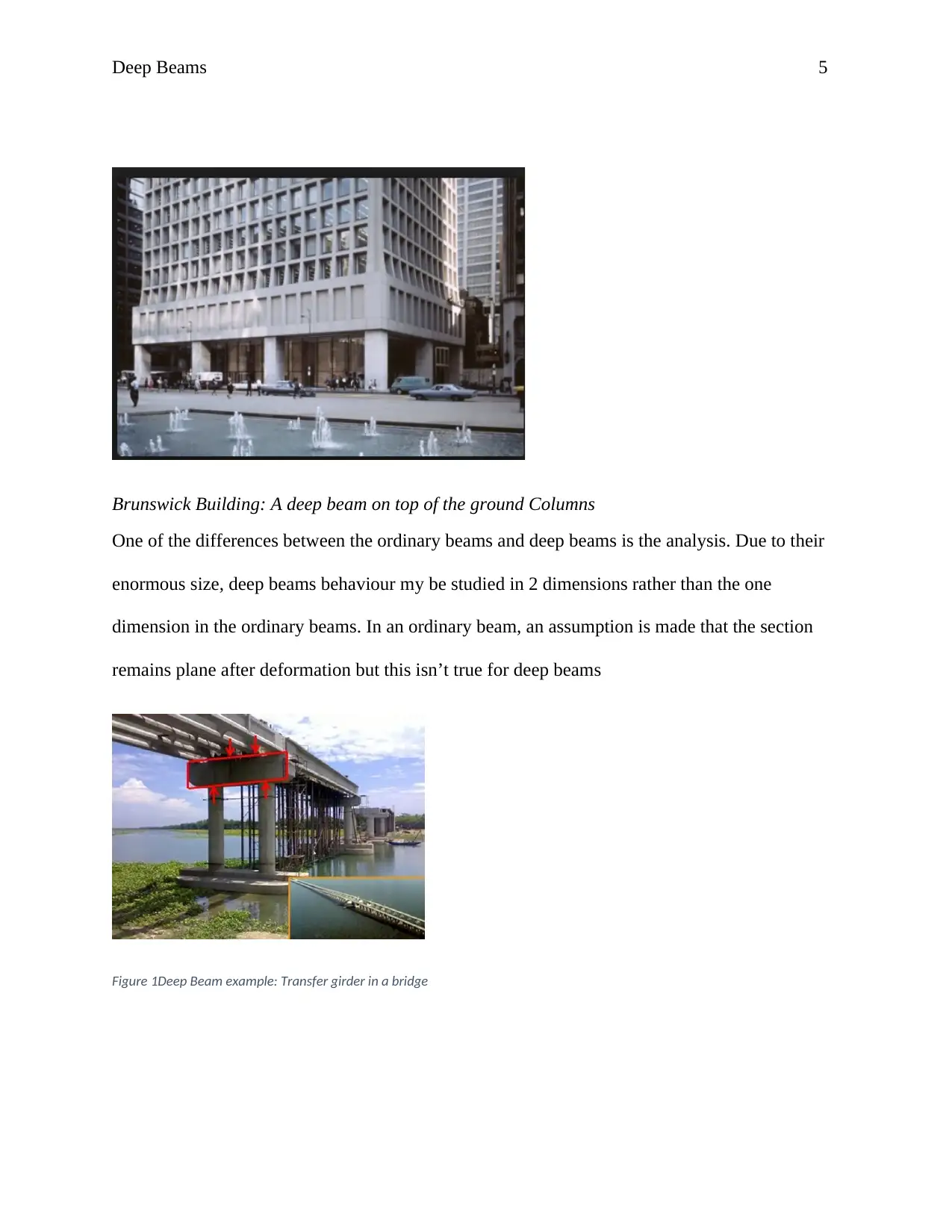
Brunswick Building: A deep beam on top of the ground Columns
One of the differences between the ordinary beams and deep beams is the analysis. Due to their
enormous size, deep beams behaviour my be studied in 2 dimensions rather than the one
dimension in the ordinary beams. In an ordinary beam, an assumption is made that the section
remains plane after deformation but this isn’t true for deep beams
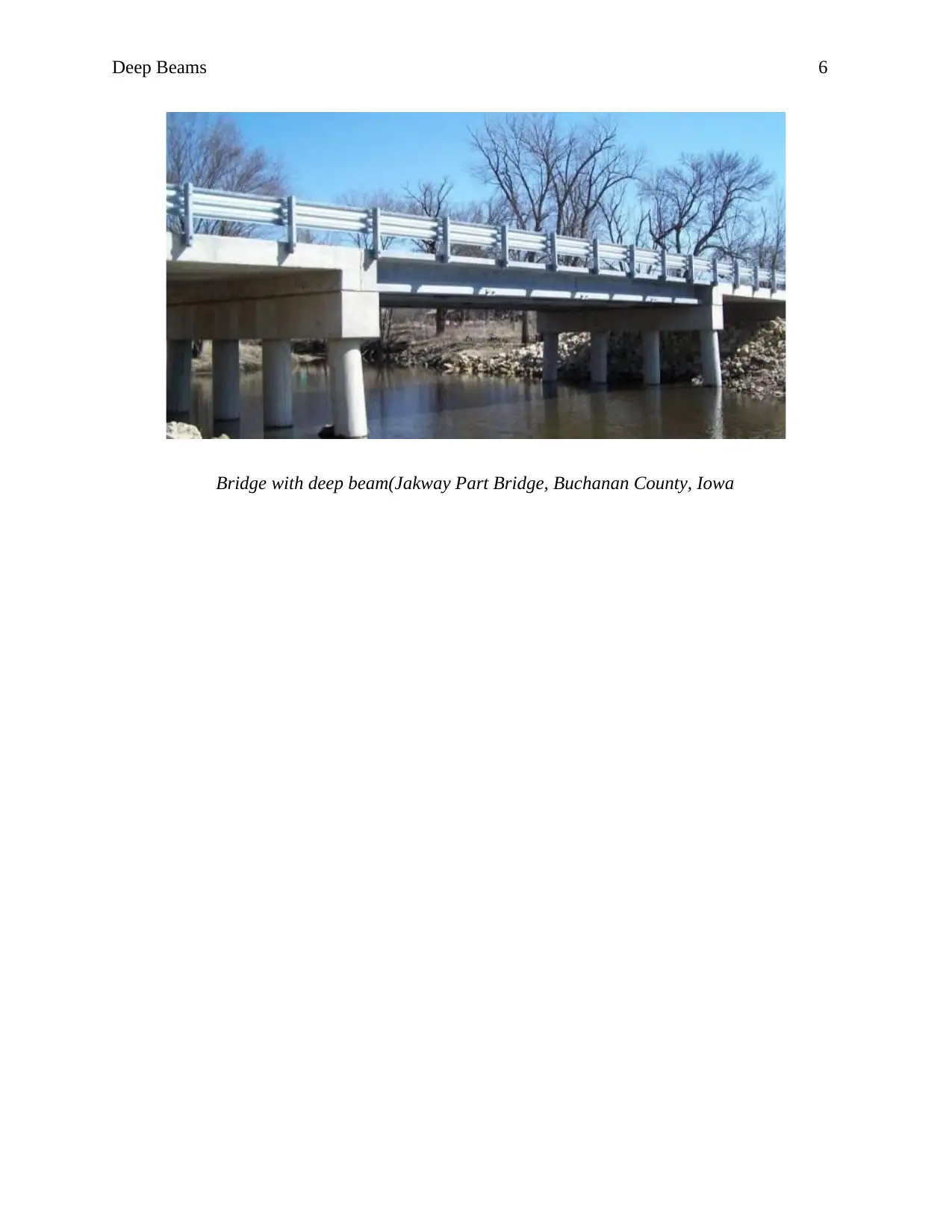
Figure 1Deep Beam example: Transfer girder in a bridge
Brunswick Building: A deep beam on top of the ground Columns
One of the differences between the ordinary beams and deep beams is the analysis. Due to their
enormous size, deep beams behaviour my be studied in 2 dimensions rather than the one
dimension in the ordinary beams. In an ordinary beam, an assumption is made that the section
remains plane after deformation but this isn’t true for deep beams
Figure 1Deep Beam example: Transfer girder in a bridge
Deep Beams 6
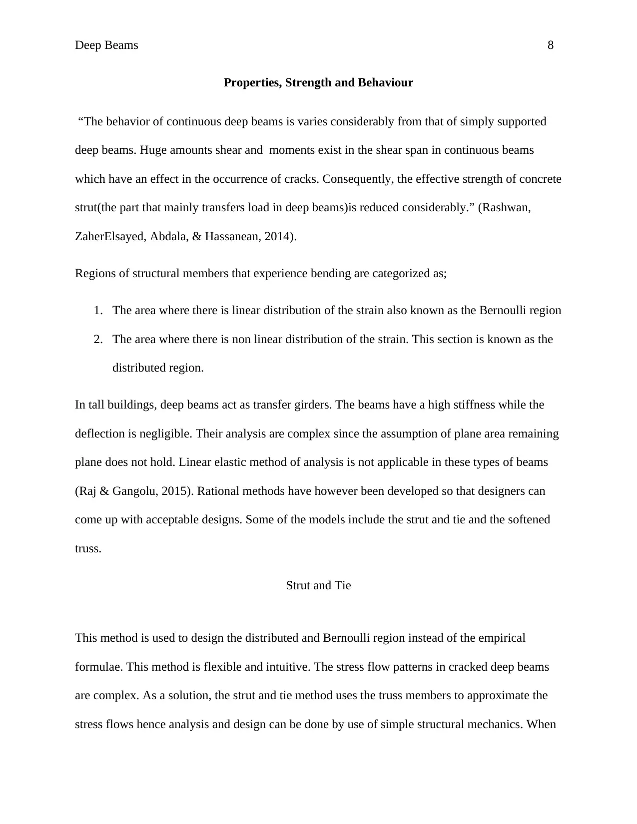
Bridge with deep beam(Jakway Part Bridge, Buchanan County, Iowa
Bridge with deep beam(Jakway Part Bridge, Buchanan County, Iowa
⊘ This is a preview!⊘
Do you want full access?
Subscribe today to unlock all pages.
Trusted by 1+ million students worldwide

Deep Beams 7
Paraphrase This Document
Need a fresh take? Get an instant paraphrase of this document with our AI Paraphraser
Deep Beams 8
Properties, Strength and Behaviour
“The behavior of continuous deep beams is varies considerably from that of simply supported
deep beams. Huge amounts shear and moments exist in the shear span in continuous beams
which have an effect in the occurrence of cracks. Consequently, the effective strength of concrete
strut(the part that mainly transfers load in deep beams)is reduced considerably.” (Rashwan,
ZaherElsayed, Abdala, & Hassanean, 2014).
Regions of structural members that experience bending are categorized as;
1. The area where there is linear distribution of the strain also known as the Bernoulli region
2. The area where there is non linear distribution of the strain. This section is known as the
distributed region.
In tall buildings, deep beams act as transfer girders. The beams have a high stiffness while the
deflection is negligible. Their analysis are complex since the assumption of plane area remaining
plane does not hold. Linear elastic method of analysis is not applicable in these types of beams
(Raj & Gangolu, 2015). Rational methods have however been developed so that designers can
come up with acceptable designs. Some of the models include the strut and tie and the softened
truss.
Strut and Tie
This method is used to design the distributed and Bernoulli region instead of the empirical
formulae. This method is flexible and intuitive. The stress flow patterns in cracked deep beams
are complex. As a solution, the strut and tie method uses the truss members to approximate the
stress flows hence analysis and design can be done by use of simple structural mechanics. When
Deep Beams 9
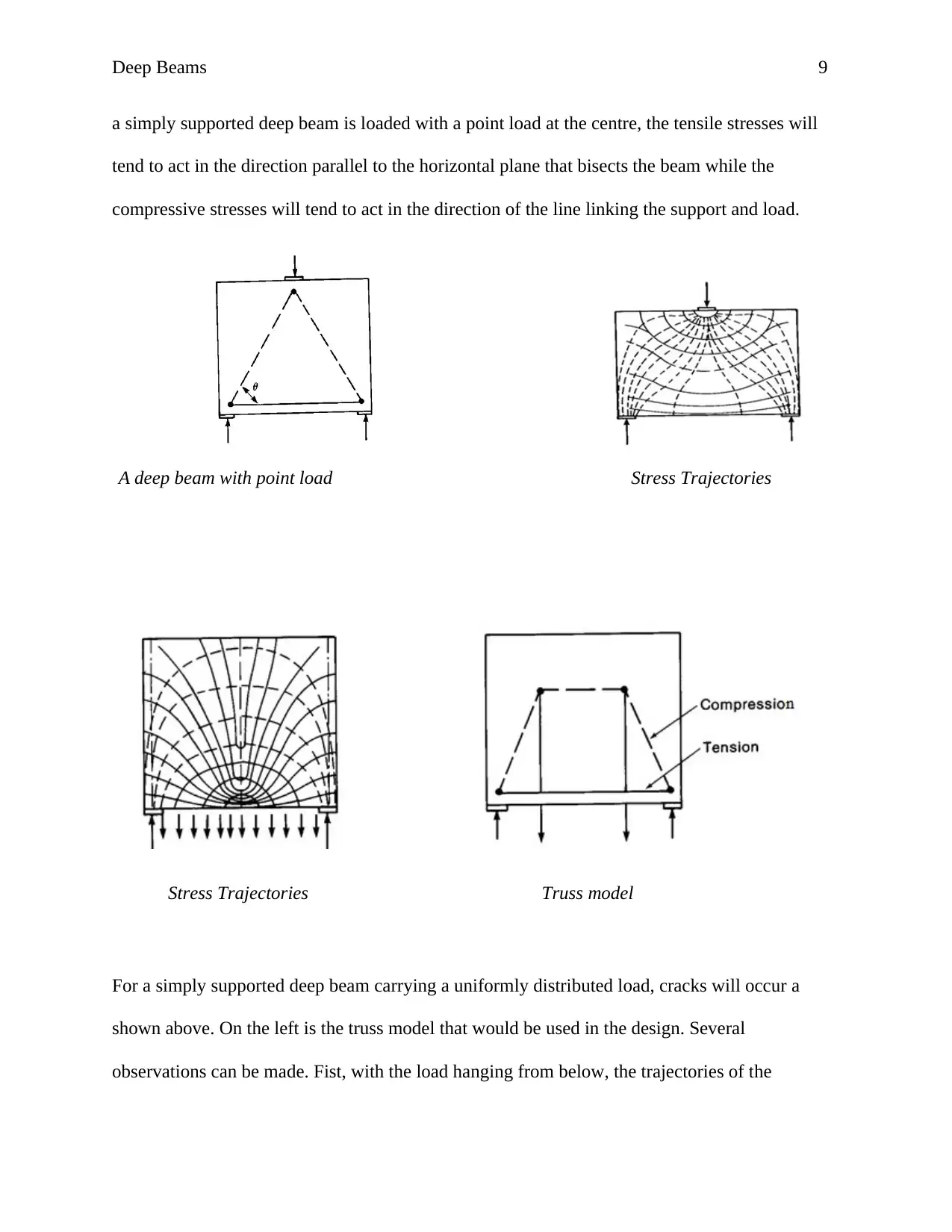
a simply supported deep beam is loaded with a point load at the centre, the tensile stresses will
tend to act in the direction parallel to the horizontal plane that bisects the beam while the
compressive stresses will tend to act in the direction of the line linking the support and load.
A deep beam with point load Stress Trajectories
Stress Trajectories Truss model
For a simply supported deep beam carrying a uniformly distributed load, cracks will occur a
shown above. On the left is the truss model that would be used in the design. Several
observations can be made. Fist, with the load hanging from below, the trajectories of the
⊘ This is a preview!⊘
Do you want full access?
Subscribe today to unlock all pages.
Trusted by 1+ million students worldwide
Deep Beams 10
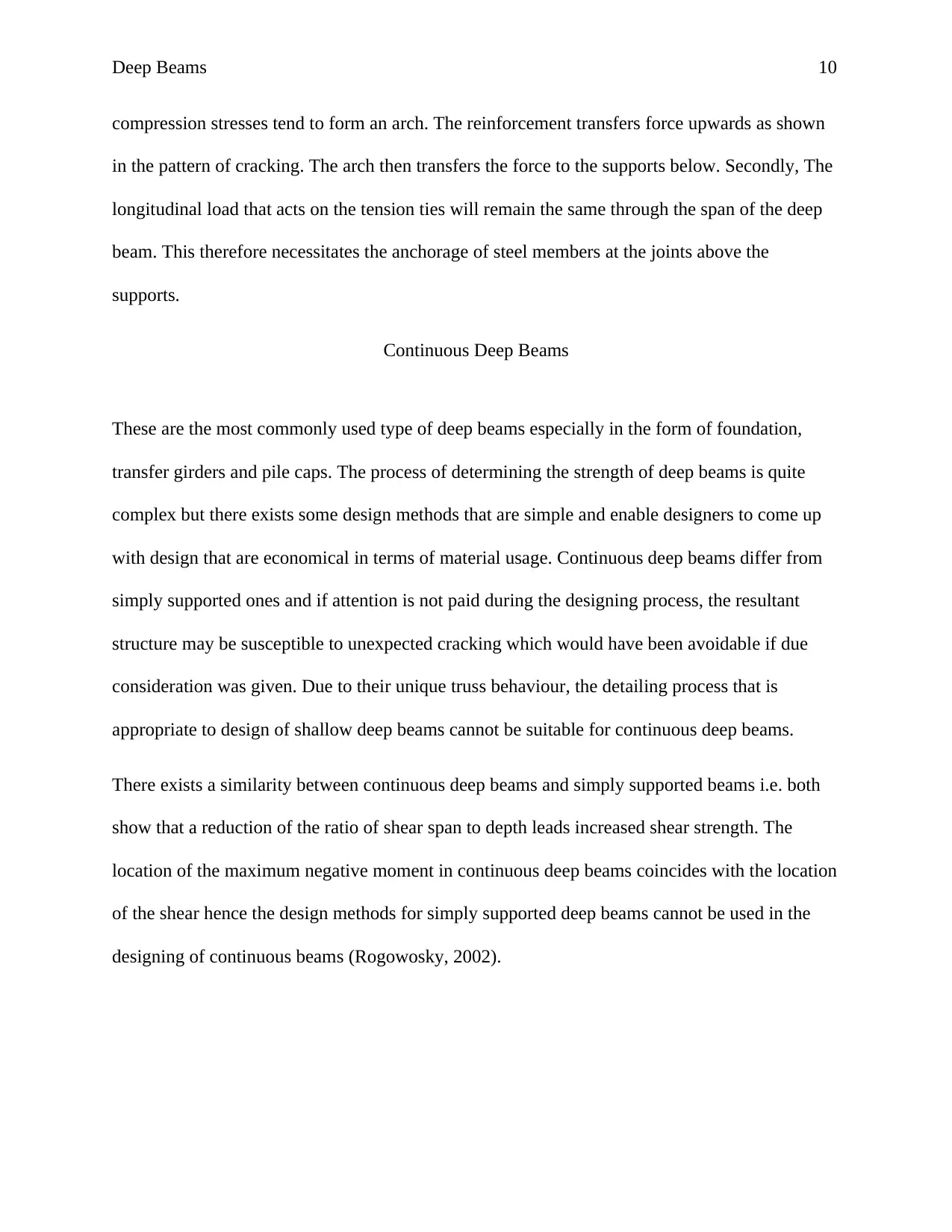
compression stresses tend to form an arch. The reinforcement transfers force upwards as shown
in the pattern of cracking. The arch then transfers the force to the supports below. Secondly, The
longitudinal load that acts on the tension ties will remain the same through the span of the deep
beam. This therefore necessitates the anchorage of steel members at the joints above the
supports.
Continuous Deep Beams
These are the most commonly used type of deep beams especially in the form of foundation,
transfer girders and pile caps. The process of determining the strength of deep beams is quite
complex but there exists some design methods that are simple and enable designers to come up
with design that are economical in terms of material usage. Continuous deep beams differ from
simply supported ones and if attention is not paid during the designing process, the resultant
structure may be susceptible to unexpected cracking which would have been avoidable if due
consideration was given. Due to their unique truss behaviour, the detailing process that is
appropriate to design of shallow deep beams cannot be suitable for continuous deep beams.
There exists a similarity between continuous deep beams and simply supported beams i.e. both
show that a reduction of the ratio of shear span to depth leads increased shear strength. The
location of the maximum negative moment in continuous deep beams coincides with the location
of the shear hence the design methods for simply supported deep beams cannot be used in the
designing of continuous beams (Rogowosky, 2002).
Paraphrase This Document
Need a fresh take? Get an instant paraphrase of this document with our AI Paraphraser
Deep Beams 11
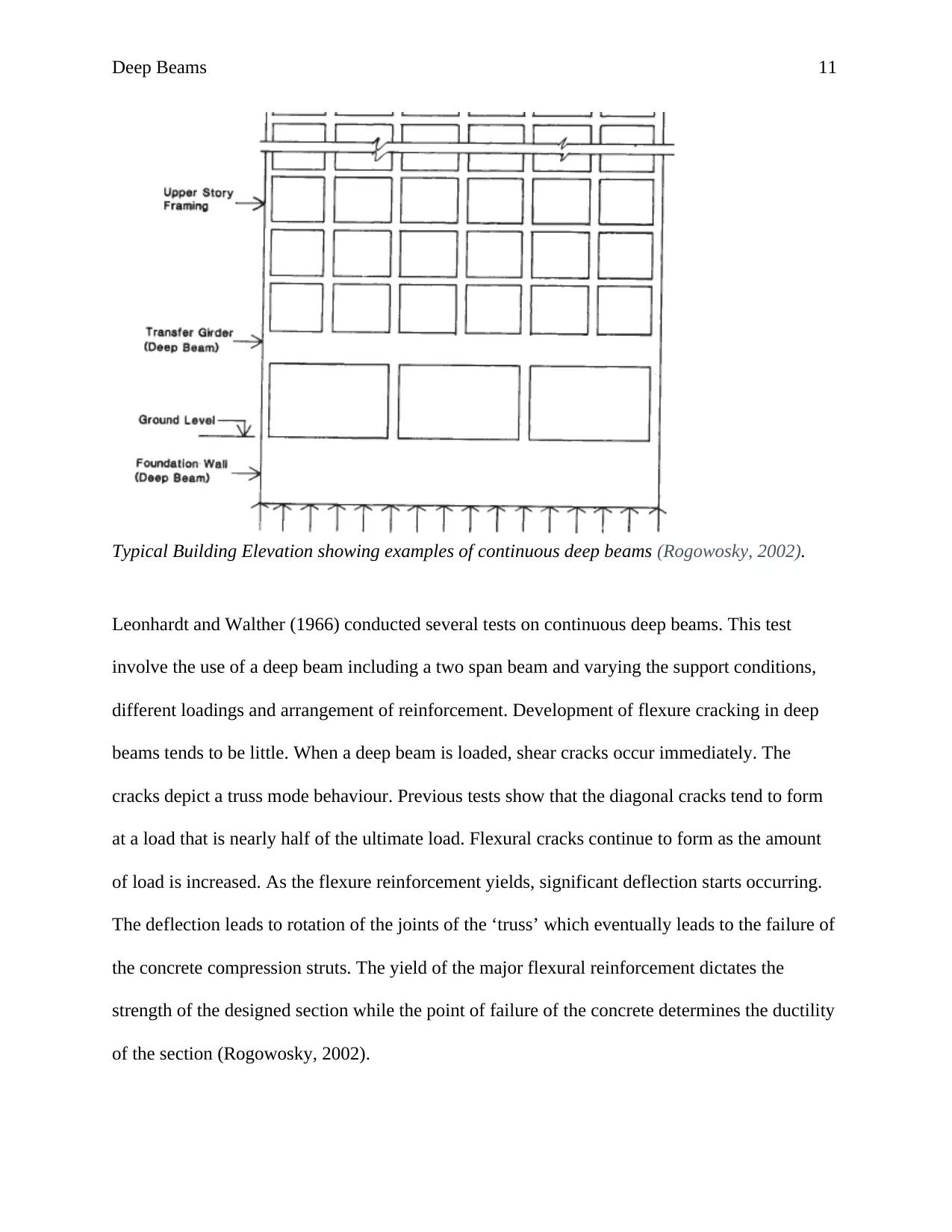
Typical Building Elevation showing examples of continuous deep beams (Rogowosky, 2002).
Leonhardt and Walther (1966) conducted several tests on continuous deep beams. This test
involve the use of a deep beam including a two span beam and varying the support conditions,
different loadings and arrangement of reinforcement. Development of flexure cracking in deep
beams tends to be little. When a deep beam is loaded, shear cracks occur immediately. The
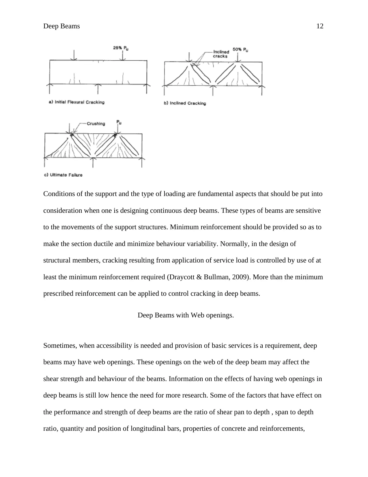
cracks depict a truss mode behaviour. Previous tests show that the diagonal cracks tend to form
at a load that is nearly half of the ultimate load. Flexural cracks continue to form as the amount
of load is increased. As the flexure reinforcement yields, significant deflection starts occurring.
The deflection leads to rotation of the joints of the ‘truss’ which eventually leads to the failure of
the concrete compression struts. The yield of the major flexural reinforcement dictates the
strength of the designed section while the point of failure of the concrete determines the ductility
of the section (Rogowosky, 2002).
Typical Building Elevation showing examples of continuous deep beams (Rogowosky, 2002).
Leonhardt and Walther (1966) conducted several tests on continuous deep beams. This test
involve the use of a deep beam including a two span beam and varying the support conditions,
different loadings and arrangement of reinforcement. Development of flexure cracking in deep
beams tends to be little. When a deep beam is loaded, shear cracks occur immediately. The
cracks depict a truss mode behaviour. Previous tests show that the diagonal cracks tend to form
at a load that is nearly half of the ultimate load. Flexural cracks continue to form as the amount
of load is increased. As the flexure reinforcement yields, significant deflection starts occurring.
The deflection leads to rotation of the joints of the ‘truss’ which eventually leads to the failure of
the concrete compression struts. The yield of the major flexural reinforcement dictates the
strength of the designed section while the point of failure of the concrete determines the ductility
of the section (Rogowosky, 2002).
Deep Beams 12
Conditions of the support and the type of loading are fundamental aspects that should be put into
consideration when one is designing continuous deep beams. These types of beams are sensitive
to the movements of the support structures. Minimum reinforcement should be provided so as to
make the section ductile and minimize behaviour variability. Normally, in the design of
structural members, cracking resulting from application of service load is controlled by use of at
least the minimum reinforcement required (Draycott & Bullman, 2009). More than the minimum
prescribed reinforcement can be applied to control cracking in deep beams.
Deep Beams with Web openings.
Sometimes, when accessibility is needed and provision of basic services is a requirement, deep
beams may have web openings. These openings on the web of the deep beam may affect the
shear strength and behaviour of the beams. Information on the effects of having web openings in
deep beams is still low hence the need for more research. Some of the factors that have effect on
the performance and strength of deep beams are the ratio of shear pan to depth , span to depth
ratio, quantity and position of longitudinal bars, properties of concrete and reinforcements,
⊘ This is a preview!⊘
Do you want full access?
Subscribe today to unlock all pages.
Trusted by 1+ million students worldwide
1 out of 21
Related Documents


Your All-in-One AI-Powered Toolkit for Academic Success.
+13062052269
info@desklib.com
Available 24*7 on WhatsApp / Email
![[object Object]](/_next/static/media/star-bottom.7253800d.svg)
Unlock your academic potential
Copyright © 2020–2026 A2Z Services. All Rights Reserved. Developed and managed by ZUCOL.