Design & Analysis of Radio Over Fiber System for Hospital - CIS117-6

Verified

Added on  2023/06/10

|16
|2190
|65
Project
AI Summary
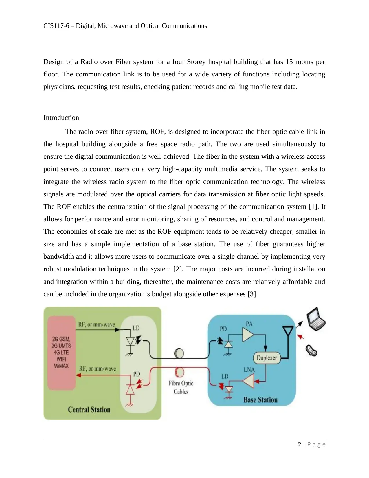
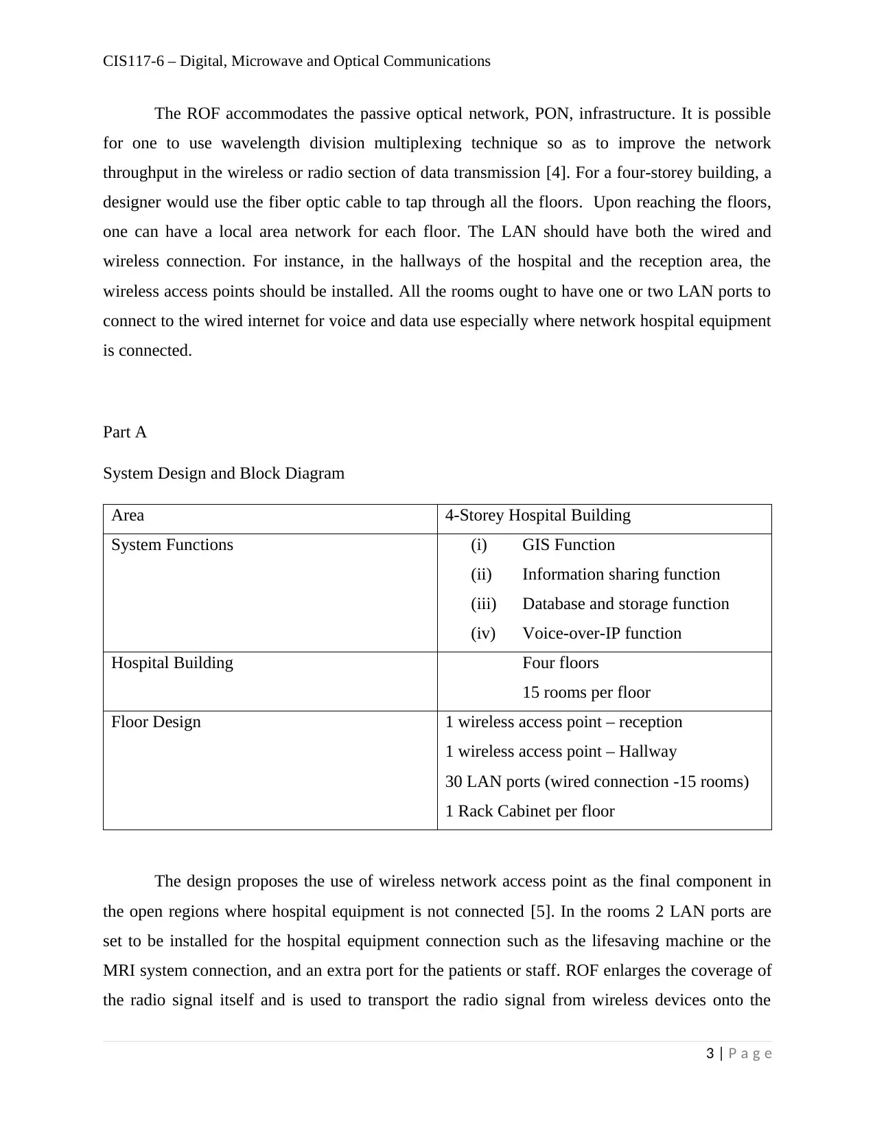
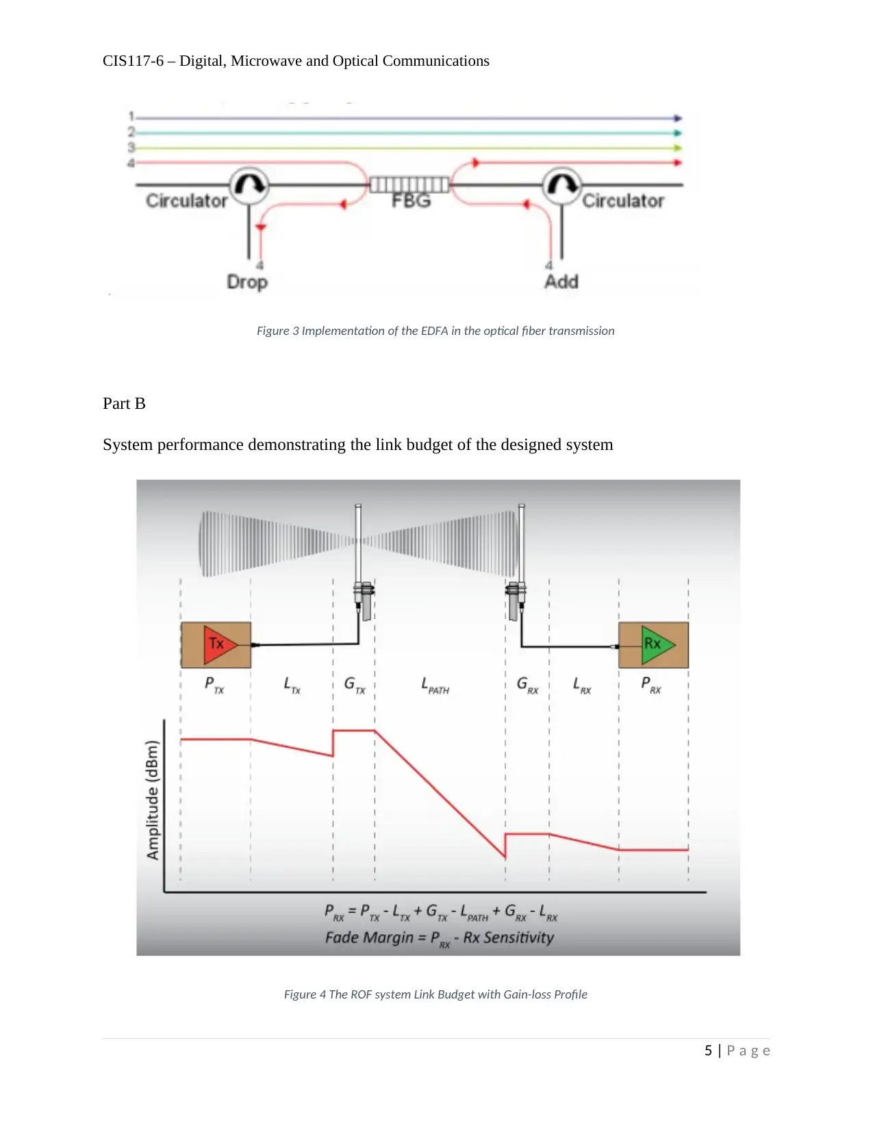
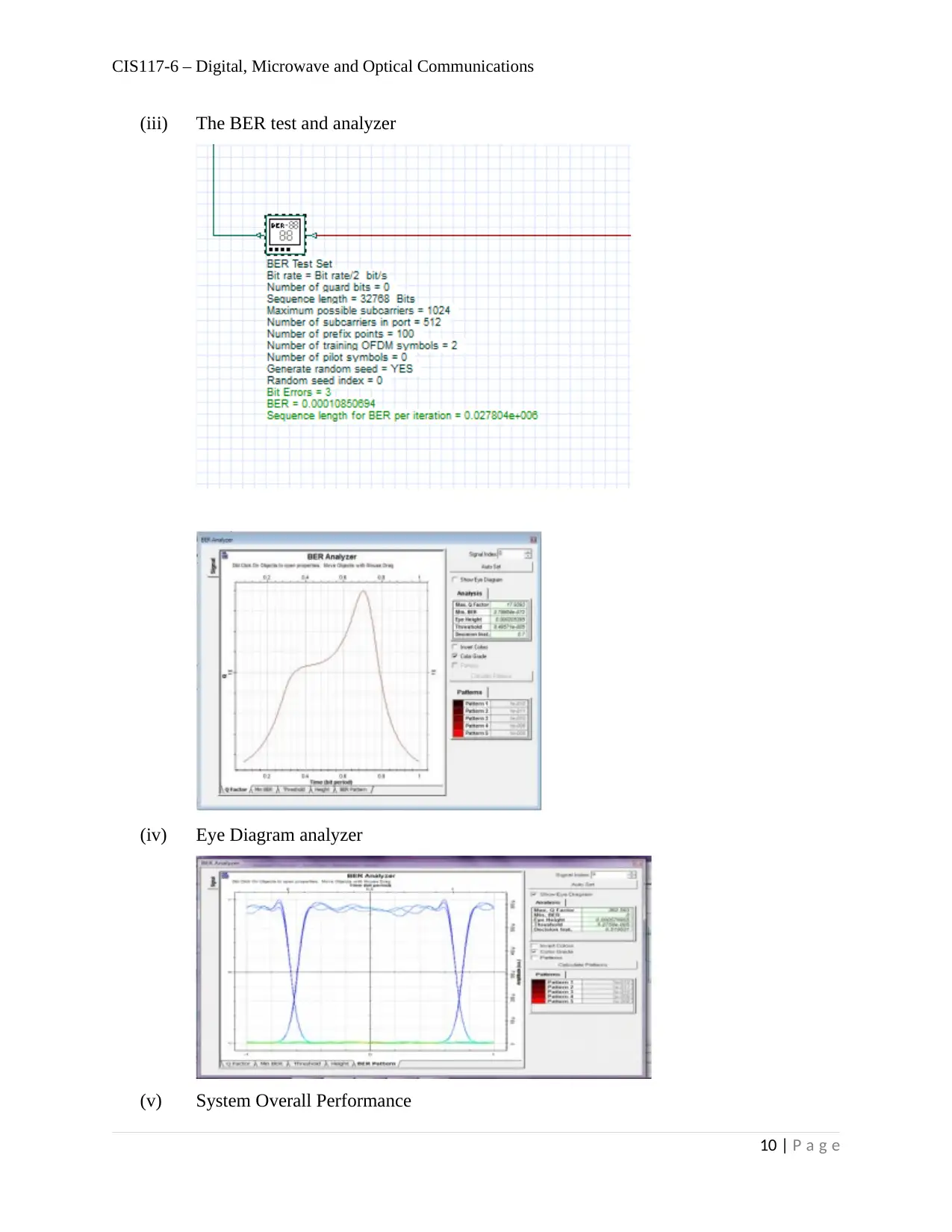
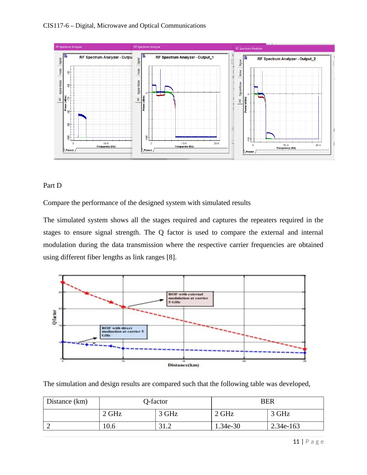
This document presents a Radio over Fiber (ROF) system design for a four-story hospital building, intended to support various communication functions such as locating physicians, accessing test results, and handling mobile test data. The design incorporates fiber optic cables and free-space radio paths, integrating wireless radio systems with fiber optic communication technology. It details the system architecture, including wireless access points, LAN ports, and rack cabinets per floor. The project includes a link budget analysis, Optiwave simulation, and performance comparison between designed and simulated results. The simulation uses LEDs, multimode fiber optic cables, and Mach-Zender modulators, with Wavelength Division Multiplexing (WDM) and Erbium-Doped Fiber Amplifiers (EDFA) to enhance signal strength. The analysis also covers the maximum number of channels the system can accommodate and compares Q-factors and Bit Error Rates (BER) under different conditions.
tabler-icon-diamond-filled.svg

Contribute Materials

Your contribution can guide someone’s learning journey. Share your documents today.
Document Page
Assignment Title:
Radio Over Fiber Systems
tabler-icon-diamond-filled.svg

Secure Best Marks with AI Grader

Need help grading? Try our AI Grader for instant feedback on your assignments.
Document Page
CIS117-6 – Digital, Microwave and Optical Communications
Design of a Radio over Fiber system for a four Storey hospital building that has 15 rooms per
floor. The communication link is to be used for a wide variety of functions including locating
physicians, requesting test results, checking patient records and calling mobile test data.
Introduction
The radio over fiber system, ROF, is designed to incorporate the fiber optic cable link in
the hospital building alongside a free space radio path. The two are used simultaneously to
ensure the digital communication is well-achieved. The fiber in the system with a wireless access
point serves to connect users on a very high-capacity multimedia service. The system seeks to
integrate the wireless radio system to the fiber optic communication technology. The wireless
signals are modulated over the optical carriers for data transmission at fiber optic light speeds.
The ROF enables the centralization of the signal processing of the communication system [1]. It
allows for performance and error monitoring, sharing of resources, and control and management.
The economies of scale are met as the ROF equipment tends to be relatively cheaper, smaller in
size and has a simple implementation of a base station. The use of fiber guarantees higher
bandwidth and it allows more users to communicate over a single channel by implementing very
robust modulation techniques in the system [2]. The major costs are incurred during installation
and integration within a building, thereafter, the maintenance costs are relatively affordable and
can be included in the organization’s budget alongside other expenses [3].
2 | P a g e
Document Page
CIS117-6 – Digital, Microwave and Optical Communications
The ROF accommodates the passive optical network, PON, infrastructure. It is possible
for one to use wavelength division multiplexing technique so as to improve the network
throughput in the wireless or radio section of data transmission [4]. For a four-storey building, a
designer would use the fiber optic cable to tap through all the floors. Upon reaching the floors,
one can have a local area network for each floor. The LAN should have both the wired and
wireless connection. For instance, in the hallways of the hospital and the reception area, the
wireless access points should be installed. All the rooms ought to have one or two LAN ports to
connect to the wired internet for voice and data use especially where network hospital equipment
is connected.
Part A
System Design and Block Diagram
Area 4-Storey Hospital Building
System Functions (i) GIS Function
(ii) Information sharing function
(iii) Database and storage function
(iv) Voice-over-IP function
Hospital Building Four floors
15 rooms per floor
Floor Design 1 wireless access point – reception
1 wireless access point – Hallway
30 LAN ports (wired connection -15 rooms)
1 Rack Cabinet per floor
The design proposes the use of wireless network access point as the final component in
the open regions where hospital equipment is not connected [5]. In the rooms 2 LAN ports are
set to be installed for the hospital equipment connection such as the lifesaving machine or the
MRI system connection, and an extra port for the patients or staff. ROF enlarges the coverage of
the radio signal itself and is used to transport the radio signal from wireless devices onto the
3 | P a g e
Document Page
CIS117-6 – Digital, Microwave and Optical Communications
optical carrier for further distribution to other remote sections [6]. The optical fiber acts as a
repeater as the connection is moved from one floor to another [7]. The design block diagram is as
illustrated below,
Figure 1 Block Diagram of System Architecture of ROF in hospital implementation
Figure 2 The multiplexing and Demultiplexing using WDM Technique for the ROF system
4 | P a g e
tabler-icon-diamond-filled.svg

Secure Best Marks with AI Grader

Need help grading? Try our AI Grader for instant feedback on your assignments.
Document Page
CIS117-6 – Digital, Microwave and Optical Communications
Figure 3 Implementation of the EDFA in the optical fiber transmission
Part B
System performance demonstrating the link budget of the designed system
Figure 4 The ROF system Link Budget with Gain-loss Profile
5 | P a g e
Document Page
CIS117-6 – Digital, Microwave and Optical Communications
Table 1 Link Budget outline for the ROF system Design
dBm
RF320 Radio (Both ends RF output power 5W 37
Sensitivity 0.25microV -119
SINAD 12dB
operating frequency 170MHz
Omnidirectional antenna FG1683
Gain 3 dBd
5.15
dBi
VSWR 2:01
Elevation of Transmitting Antenna 30 m
Transmission line at Transmitter pm31332 Surge Suppression kit 0.5dB loss
Receiver 0.5dB loss
OFDM 1Gbps
Distance between floors 4m
floor Hallway length 1000m
Part C
System implementation on Optiwave and performance analysis
The system is simulated on the Optisystem simulator using two LEDs as the transmission
distance is on a short range and multimode fiber optic cables are implemented. The Mach-Zender
modulator is used to capture the incoming signals from the pseudo-random bit sequence. The
NRX signals are mixed with the message signal before being modulated. The input comprises of
6 | P a g e
Document Page
CIS117-6 – Digital, Microwave and Optical Communications
4 inputs from the 4 floors and the signals are modulated despite being at different wavelengths.
The difference in wavelength enables the transmission over multimode fiber within the hospital.
7 | P a g e
tabler-icon-diamond-filled.svg

Paraphrase This Document

Need a fresh take? Get an instant paraphrase of this document with our AI Paraphraser
Document Page
CIS117-6 – Digital, Microwave and Optical Communications
When the system needs to communicate with the extranet or the internet, a single mode fiber is
used and hence the message signals are multiplexed for transmission. The multiplexing is done
using the Wavelength Division Multiplexing technique and amplified to give the signals a huge
initial boost using the EDFA. A repeater is added by using the OADM for each floor at the
inception connection point of every floor. This ensures that despite the distance a room is from
the base station, the connection is still very strong and speed are more or less constant on every
floor. When a repeater is not implemented, the signal weakens and some rooms have very slow
speeds of connection unlike others.
(i) RF Spectrum Analyzer
8 | P a g e
Document Page
CIS117-6 – Digital, Microwave and Optical Communications
(ii) The transmitted signal with noise
9 | P a g e
Document Page
CIS117-6 – Digital, Microwave and Optical Communications
(iii) The BER test and analyzer
(iv) Eye Diagram analyzer
(v) System Overall Performance
10 | P a g e
tabler-icon-diamond-filled.svg

Secure Best Marks with AI Grader

Need help grading? Try our AI Grader for instant feedback on your assignments.
Document Page
CIS117-6 – Digital, Microwave and Optical Communications
Part D
Compare the performance of the designed system with simulated results
The simulated system shows all the stages required and captures the repeaters required in the
stages to ensure signal strength. The Q factor is used to compare the external and internal
modulation during the data transmission where the respective carrier frequencies are obtained
using different fiber lengths as link ranges [8].
The simulation and design results are compared such that the following table was developed,
Distance (km) Q-factor BER
2 GHz 3 GHz 2 GHz 3 GHz
2 10.6 31.2 1.34e-30 2.34e-163
11 | P a g e
Document Page
CIS117-6 – Digital, Microwave and Optical Communications
4 8.7 18.7 3.6e-22 4.02e-79
6 6.8 12.6 7.4e-16 2.9e-43
8 6.4 9.5 4.5e-22 3.05e-79
10 4.8 7.8 6.5e-9 3.56e-18
The simulation uses the lasers that are turned on for data transmission purposes and the
noise for the photodiodes that tend to receive an optical signal from another laser by
incorporating the ambient noise in addition of noise conversions. The interference and other
instances of loss are well curbed in the simulation and some may not have been well factored in
during the design. The design captures the key losses during transmission and the simulation
takes into consideration more details on the loss factors and ensures that the designer has
indicated values in all the instances [9].
The eye diagram analyzer block of the Optisystem software displays multiple traces of a
modulated signal to produce an eye diagram. In downstream eye diagram we have calculate Bit
error rate (BER) & Received optical power (dBm). In telecommunication, an eye pattern, also
known as an eye diagram is an oscilloscope display in which a digital data signal from a receiver
is respectively sampled and applied to the vertical input. While the data rate is used to trigger the
horizontal sweep. It is so called because, for several types of coding the pattern looks like a
series of eyes between a pair of rails. In downstream when bit error rate -4 dB than received
optical power is -21 dBm.
The Erbium doped fiber amplifier is used in amplification of the optical signals during
transmission over a number of kilometers from the source point. They are quite useful as
repeaters in the long-distance communication and depicts a fiber loss of up to 0.2dB per km. The
optical spectrum analyzer depicts the signals presented at the receiver.
12 | P a g e
Document Page
CIS117-6 – Digital, Microwave and Optical Communications
The NRZ coding is used in the design of the ROF on Optisystem software. It tends
to suffers some form of non-linearities during the assimilation of the sine wave generator input
[10]. The RZ coding tends to suffer dispersion for the shorter pulse widths. During modulation,
the coding techniques demonstrate a very high-power regime which is needed in the transmission
of messages from the hospital equipment with the source as plain data, video, or voice [11].
Part E
Maximum number of channels that the system can accommodate. Demonstrate the solution on
Optiwave.
For the uplink transmission,
f max
n2
f 3 2 f mn
n2 1
1 n2 I 3 [ f max
f max f min ]
13 | P a g e
tabler-icon-diamond-filled.svg

Paraphrase This Document

Need a fresh take? Get an instant paraphrase of this document with our AI Paraphraser
Document Page
CIS117-6 – Digital, Microwave and Optical Communications
ARFCN=8 channels for radio communication
With connection to fiber, the channels still remain as 8 but the multiplexing improves the output.
References
14 | P a g e
Document Page
CIS117-6 – Digital, Microwave and Optical Communications
[1] I. B. F. S. M. C. A. C. H. S. Y. G. G. A.Pizzinat, "Low Cost Transparent Radio-over-Fibre
System for UWB Based Home Network," European Conference on Optical
Communications , pp. 21-25, 2008.
[2] H. A.-R. S. M. F. a. R. N. S. R. Abdollahi, "All Photonic Analogue to Digital and Digital to
Analogue Conversion Techniques," Radio over Fibre (RoF) Technique, pp. 1-2, 7 January
2010.
[3] I. B. S. C. H. S. M. C. A. Y. G. P. G. A.Pizzinat, "Ultra Wide Band Home Networks by
Means of a Low Cost Radio-over-MultiMode-Fibre Transparent System," Network and
Optical Communications , pp. 1-3, 2008.
[4] S. K. H. Al Raweshidi, "Radio over Fiber Technologies for Mobile Communication
Network," Artech House, London, 2002.
[5] S. G. A. A. B. N. S. F. I. G. D. H. S. C. A. S. J. C. M. C. Y. G. S.Paquelet,
"RNRT/BILBAO project: first results on Ultra Wide Band over fiber," International UWB
Workshop , 2007.
[6] Xiaolong Li, "Simulink-based Simulation of Quadrature Amplitude Modulation (QAM)
System," Proceedings of IAJC-IJME .
[7] M. A. S. P. B. M.Huchard, "Ultra Broad Band Wireless Home Network based on 60GHz
WPANs cells interconnected via RoF," Invited paper IEEE Journal of Lightwave
Technology, 2010.
[8] M. Mohammad, A. Shehad, A. Kadhim, R. A. Qusay and M. S. Lateef, "Design and
Simulation of External Modulation Technique Based on ROF communication System,"
International Journal of Engineering Sciences and Research Technology, vol. 6, no. 7, pp.
702-709, 2017.
[9] Y. (. Yang, "Investigation on Digitized RF Transport over Fiber," Phd Thesis, pp. 34-67,
2011.
[10] N. Hamim and M. I. Sevia, "Modeling and Performance Analysis of WCDMA Radio over
Fiber System," Asia Pacific Conference on Applied Electromagnetic proceedings,
Photonics Technology Center, Malaysia, 2007.
[11] S. Shweta and K. Vanita, "Performance Evaluation of Digital Modulation Techniques for
WCDMA using Radio over Fiber," IJECT, vol. 2, no. 3, 2011.
15 | P a g e
Document Page
CIS117-6 – Digital, Microwave and Optical Communications
16 | P a g e
chevron_up_icon
1 out of 16
circle_padding
hide_on_mobile
zoom_out_icon
logo.png

Your All-in-One AI-Powered Toolkit for Academic Success.

Available 24*7 on WhatsApp / Email

[object Object]