Design and Construction Review: Reciprocating Engine Analysis

Verified

Added on  2020/03/04

|4
|766
|339
Report
AI Summary
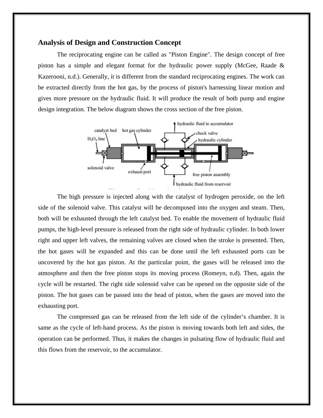
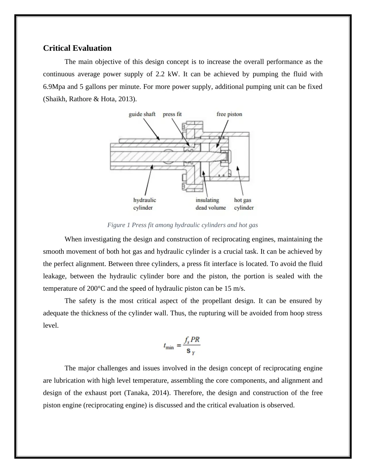
This report provides an analysis of the design and construction of reciprocating engines, specifically focusing on the 'free piston' engine concept. The report discusses the engine's operational principles, highlighting its unique approach to hydraulic power generation through the direct harnessing of the piston's linear motion. The design integrates a pump and engine, extracting work from hot gas to pressurize hydraulic fluid. The report details the engine's operational cycle, including the role of solenoid valves, catalyst beds, and the expansion of hot gases. Furthermore, it evaluates the design concept, emphasizing the objective of achieving a continuous average power supply of 2.2 kW. Critical aspects of the design, such as the press fit interface between hydraulic cylinders and hot gas cylinders, along with safety considerations like cylinder wall thickness, are also addressed. The report concludes by acknowledging challenges in lubrication, component assembly, and exhaust port design. The document references several sources to support the analysis.
Document Page
Review on Design &
Construction of
Reciprocating Engine
tabler-icon-diamond-filled.svg

Paraphrase This Document

Need a fresh take? Get an instant paraphrase of this document with our AI Paraphraser
Document Page
Analysis of Design and Construction Concept
The reciprocating engine can be called as "Piston Engine". The design concept of free
piston has a simple and elegant format for the hydraulic power supply (McGee, Raade &
Kazerooni, n.d.). Generally, it is different from the standard reciprocating engines. The work can
be extracted directly from the hot gas, by the process of piston's harnessing linear motion and
gives more pressure on the hydraulic fluid. It will produce the result of both pump and engine
design integration. The below diagram shows the cross section of the free piston.
The high pressure is injected along with the catalyst of hydrogen peroxide, on the left
side of the solenoid valve. This catalyst will be decomposed into the oxygen and steam. Then,
both will be exhausted through the left catalyst bed. To enable the movement of hydraulic fluid
pumps, the high-level pressure is released from the right side of hydraulic cylinder. In both lower
right and upper left valves, the remaining valves are closed when the stroke is presented. Then,
the hot gases will be expanded and this can be done until the left exhausted ports can be
uncovered by the hot gas piston. At the particular point, the gases will be released into the
atmosphere and then the free piston stops its moving process (Romeyn, n.d). Then, again the
cycle will be restarted. The right side solenoid valve can be opened on the opposite side of the
piston. The hot gases can be passed into the head of piston, when the gases are moved into the
exhausting port.
The compressed gas can be released from the left side of the cylinder’s chamber. It is
same as the cycle of left-hand process. As the piston is moving towards both left and sides, the
operation can be performed. Thus, it makes the changes in pulsating flow of hydraulic fluid and
this flows from the reservoir, to the accumulator.
Document Page
Critical Evaluation
The main objective of this design concept is to increase the overall performance as the
continuous average power supply of 2.2 kW. It can be achieved by pumping the fluid with
6.9Mpa and 5 gallons per minute. For more power supply, additional pumping unit can be fixed
(Shaikh, Rathore & Hota, 2013).
Figure 1 Press fit among hydraulic cylinders and hot gas
When investigating the design and construction of reciprocating engines, maintaining the
smooth movement of both hot gas and hydraulic cylinder is a crucial task. It can be achieved by
the perfect alignment. Between three cylinders, a press fit interface is located. To avoid the fluid
leakage, between the hydraulic cylinder bore and the piston, the portion is sealed with the
temperature of 200°C and the speed of hydraulic piston can be 15 m/s.
The safety is the most critical aspect of the propellant design. It can be ensured by
adequate the thickness of the cylinder wall. Thus, the rupturing will be avoided from hoop stress
level.
The major challenges and issues involved in the design concept of reciprocating engine
are lubrication with high level temperature, assembling the core components, and alignment and
design of the exhaust port (Tanaka, 2014). Therefore, the design and construction of the free
piston engine (reciprocating engine) is discussed and the critical evaluation is observed.
Document Page
References
McGee, T., Raade, J., & Kazerooni, H. Monopropellant-Driven Free Piston Hydraulic Pump for
Mobile Robotic Systems. Journal Of Dynamic Systems, Measurement, And Control, 126(1),
75. http://dx.doi.org/10.1115/1.1649972
Romeyn, A. http://www.asasi.org/papers/2004/Romeyn_Propulsion%20Failure_ISASI04.pdf.
Retrieved 12 August 2017, from http://www.asasi.org/papers/2004/Romeyn_Propulsion
%20Failure_ISASI04.pdf
Shaikh, D., Rathore, M., & Hota, P. (2013). Magnetic Repulsion Piston Engine. International
Journal Of Science And Research (IJSR). Retrieved from
https://www.ijsr.net/archive/v4i12/NOV151877.pdf
Tanaka, J. (2014). DESIGN OF PISTON RING SURFACE TREATMENT FOR REDUCING
LUBRICATING OIL CONSUMPTION. MM Science Journal, 2014(04), 533-536.
http://dx.doi.org/10.17973/mmsj.2014_12_201420
chevron_up_icon
1 out of 4
circle_padding
hide_on_mobile
zoom_out_icon
[object Object]