Design & Fabrication of 3-Phase Induction Motor with Microcontroller
VerifiedAdded on 2023/06/10
|8
|1832
|205
Project
AI Summary
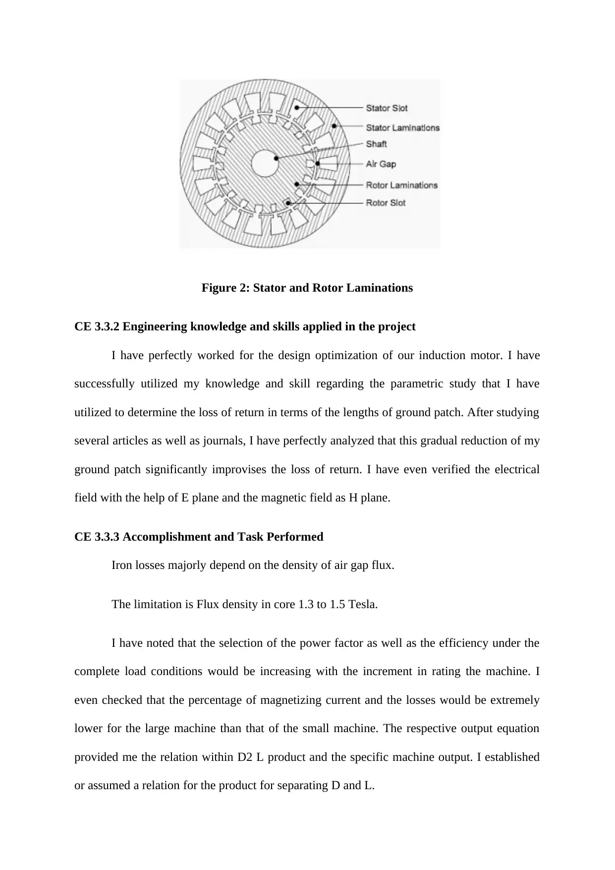
This project documents the design and fabrication of a three-phase squirrel cage induction motor with a microcontroller, undertaken to address a specific equipment compatibility issue. The project outlines the background, objectives, and the engineer's responsibilities, including parameter identification, time domain analysis, and prototype development. Key activities included understanding the theory of induction motors, applying engineering knowledge for design optimization, and addressing issues related to power quality through grounding, bonding, and proper wiring. The project successfully designed and fabricated a functional three-phase induction motor, demonstrating the application of theoretical knowledge and practical skills in electrical engineering. Desklib offers a variety of solved assignments and project reports for students.

CE 3.1 Project Information
Name of the project: Design and Fabrication of Three Phase Induction Motor with
Microcontroller
Location of the project: Doha- Qatar
Project Duration: One month
Organization: Q-Kitchen
Role and Designation during the time: Maintenance Engineer
CE 3.2 Project Background
CE 3.2.1 Characteristics of the project
The significant idea of this project came up into my mind when I received by mistake
from one of our suppliers a machine of Dough Mixer that was ordered according to the
American standard 3Phase 220Volt while the Standard in the middle east is 3Phase 380-
415Volt.when I claimed from the supplier to change the motor they refused to because this is
not considered a warranty claim and we have to be charged 2000€ ex-work Italy. Then I
decided to gather all of my engineering knowledge and background to solve that problem and
to design and fabricate a new motor locally that can be operated with the available power.
The three phase induction motors are the AC electrical motors, where the respective electric
current is needed in the rotor for producing torque and is thus obtained by the help of
electromagnetic inductions. There are specifically two types of rotors in induction motor.
They are either squirrel cage type or the wound type. After dismantling the existing motor I
discovered that it was Squirrel then I decided to use the same. During the project, I have
successfully designed as well as fabricated the three phase induction motor with a specific
Paraphrase This Document
Need a fresh take? Get an instant paraphrase of this document with our AI Paraphraser

microcontroller. I have designed the three phase squirrel cage induction motors since these
are reliable, rugged and economical. I have used the variable frequency drives or VFDs in
this the variable speed services. I have worked in the region of 380 to 415 three phase voltage
and the frequency was 50 Hz. I have utilized 4 wires in this project since I did not include any
ground wire. I have also utilized the C/F plug type here to properly execute the project.
Therefore, I have investigated and finally documented the project report regarding the
squirrel case induction motor that I have designed with the microcontroller.
CE 3.2.2 Objectives developed for the project
The three phase induction motors are the typical AC motors that are solely utilized as
the prime movers within every aspect. I have used power controls, beater, mixing hook,
fixing guard, control panel, mixer blades and handle tilts within the design of Dough mixer
machine. While designing this three phase induction motor, I have developed some of the
major objectives. They are as follows:
To propose a design of the three phase induction motor.
To use a squirrel cage induction motor for my project.
To make the difference from the DC machine in terms of commutator, stator, air gap
and constant speed.
To use microcontroller for designing and fabricating the three phase induction motor.
To set up the experiment for designing induction motor.
To compare and analyze the experimental results with the previous researches for
obtaining better solution.
CE 3.2.3 My area of work
While working on the project of designing and fabrication of the three phase squirrel
cage induction motor with the help of microcontroller, I had to clear all the doubts related to

Team Leader
Chief Electrical
Engineer
Maintenance
Engineer (Me)
Draftsman
this induction motor. For this purpose, I investigated about the past experiments of induction
motors for making a significant difference from the DC machine in respect to laminated
stator and commutator. I made sure that the speed was kept absolutely constant. I have further
understood and applied the skill and knowledge related to induction motor. Moreover, I have
also developed the entire set up to conduct a proper experiment for the performance analysis
of three phase induction motor. Finally, I have also proposed a significant preliminary
designing of my induction motor before the development of the prototype model.
CE 3.2.4 Project Group
Figure 1: People involved in the project
CE 3.2.5 My responsibilities throughout the project
In this project, I undertook the core responsibility of recognizing the several
parameters needed to develop our prototype model of the squirrel cage induction motor. I
have even properly conducted the perfect analysis of time domain with the help of CST
Microwave Studio. Moreover, for the purpose of conducting the significant numerical
⊘ This is a preview!⊘
Do you want full access?
Subscribe today to unlock all pages.

Trusted by 1+ million students worldwide

analysis of my microcontroller, I have utilized proper theories and practical experiments.
After getting the optimum result from my analysis, I have developed and fabricated the
designed prototype model of three phase induction motor with the help of the Printed Circuit
Board. I have even ensured the operational functionality and efficiency of the designed
model. I have even compared and analyzed the experimental data and results obtained from
my previous researches. I also assisted in the preparation of equipment procurement plan and
then reviewed the implementation so that I can ensure it being available all the time.
Moreover, I even had to coordinate the project with the respective internal team or sub
contractor in respect to material specification, material quality and time schedule.
CE 3.3 Distinctive Activity
CE 3.3.1 Comprehending the Theory of Project
Rotor can be defined as the rotating portion of a three phase induction motor. This
rotor even comprises of the collection of the slotted silicon steel laminations that are pressed
altogether for the purpose of forming a proper cylindrical magnetic circuit as well as the
electrical circuit. The squirrel cage rotor comprises of the collection of aluminium or copper
bars that are installed to the respective slots that are linked to the end ring at every end of this
rotor. The major reason to design a three phase induction motor is obtaining the entire
physical dimension of each and every part of the machine.
Paraphrase This Document
Need a fresh take? Get an instant paraphrase of this document with our AI Paraphraser

Figure 2: Stator and Rotor Laminations
CE 3.3.2 Engineering knowledge and skills applied in the project
I have perfectly worked for the design optimization of our induction motor. I have
successfully utilized my knowledge and skill regarding the parametric study that I have
utilized to determine the loss of return in terms of the lengths of ground patch. After studying
several articles as well as journals, I have perfectly analyzed that this gradual reduction of my
ground patch significantly improvises the loss of return. I have even verified the electrical
field with the help of E plane and the magnetic field as H plane.
CE 3.3.3 Accomplishment and Task Performed
Iron losses majorly depend on the density of air gap flux.
The limitation is Flux density in core 1.3 to 1.5 Tesla.
I have noted that the selection of the power factor as well as the efficiency under the
complete load conditions would be increasing with the increment in rating the machine. I
even checked that the percentage of magnetizing current and the losses would be extremely
lower for the large machine than that of the small machine. The respective output equation
provided me the relation within D2 L product and the specific machine output. I established
or assumed a relation for the product for separating D and L.

Flux within the stator core section Φc = ½ Φ
The area of the stator core Ac = Φ/2Bc
The area of the stator core Ac = Li x dcs.
Therefore, the core depth = Ac / Li
With the help of the design data that I have obtained, I calculated the outer diameter
of the stator
Do = D + 2hss = 2 dcs where hss is the stator slot height.
CE 3.3.4 Identified issues and their solutions
3.3.4.1 Issues
The first issue that I had faced here was the issue related to power quality. The well-
known use of the electronic equipment such as the equipments of information technology was
the main issue that I had faced here. The PLC or the programmable logic controllers and the
ASD or the adjustable speed drives were the two examples of our power electronics and
hence leading to the entire alteration of the nature of electric load. All of these loads were the
major causers and the major reasons of the issues that are related to the power quality. For the
cause of the non linearity, the typical loads, which had caused several disturbances in the
waveform of voltages, were faced by me.
3.3.4.2 Solutions
For solving each and every above mentioned problem, I suggested some of the easiest
solutions. For the first significant issue of power quality, I provided the suggestion of
grounding and bonding. Grounding can be defined as one of the most significant aspects of
electrical systems. The specific safety ground is responsible for protecting the electrical
⊘ This is a preview!⊘
Do you want full access?
Subscribe today to unlock all pages.

Trusted by 1+ million students worldwide

systems and the equipments from all the super imposed voltages that are caused by the
lightning or the accidental contacts with the high voltage systems. For the next issue, I gave
the suggestion of proper wiring. The total equipment inspection was the most crucial factor to
ensure proper wirings in the facility. The entire electrical system should be eventually
checked for all the missing, loose and the improper links in the panels as well as the
equipments.
CE 3.3.5 Plan to produce creative and innovative work
My major and significant plan was producing the most innovative as well as creative
works by efficiently working together. I even divided the entire works perfectly and each and
every task was being eventually executed perfectly.
CE 3.3.6 Collaborative Work
I have successfully worked with my project members and project leader for efficiently
and successfully completing the development of the squirrel cage three phase For the issues
faced in this project during the process of fabrication, I have discussed the same with my
project team for solving these issues with higher efficiencies.
CE 3.4 Project Review
CE 3.4.1 Project Overview
I was effectively simulating and optimizing the designing to develop the respective
prototype model. With the prototype induction motor model, I ensured that the operation
capability was done within proper range. Therefore, I was successful in designing a three
phase induction motor with microcontroller.
Paraphrase This Document
Need a fresh take? Get an instant paraphrase of this document with our AI Paraphraser

CE 3.4.2 My Contribution to work
I have successfully applied the method of impedance matching, which has enabled me
to enhance the efficiency of bandwidth of the induction motor model. I have applied my
knowledge for concrete slabs to design as well as fabricate the three phase induction motor
with the help of microcontroller.
I have successfully applied the method of impedance matching, which has enabled me
to enhance the efficiency of bandwidth of the induction motor model. I have applied my
knowledge for concrete slabs to design as well as fabricate the three phase induction motor
with the help of microcontroller.
1 out of 8
Related Documents

Your All-in-One AI-Powered Toolkit for Academic Success.
+13062052269
info@desklib.com
Available 24*7 on WhatsApp / Email
Unlock your academic potential
Copyright © 2020–2025 A2Z Services. All Rights Reserved. Developed and managed by ZUCOL.