Mechanical Design and Mechanics of a Lower Half Body Prosthesis
VerifiedAdded on 2023/06/09
|29
|5360
|109
Report
AI Summary
This report details the design and fabrication of a Lower Half Body Prosthesis, focusing on creating a simple, low-cost solution that facilitates a full gait cycle with minimal difficulty for the user. The design integrates modular sensors and controllers, emphasizing simplicity, durability, and ease of maintenance. It combines the mechanical structure of the prosthesis with a smart control computerized system to enable dynamic mobility. The design incorporates engineering principles, including the Lagrangian ODE expression for analyzing the prosthesis's dynamics. The report discusses the requirements and specifications of the prosthesis, highlighting its potential contribution to the smart prosthetic industry. It also covers aspects like mechanical design features, degrees of freedom, dynamics modeling, and considerations for inclination angles, supported by figures, tables, and appendices with decision matrices, supplier lists, calculations, and software-based numerical analysis.
Design and Mechanics of Lower Half Body Prosthesis
Name
Institution
Name
Institution
Paraphrase This Document
Need a fresh take? Get an instant paraphrase of this document with our AI Paraphraser
Design of a Lower Half Body Prosthesis 2
Executive Summary
This report details the design and fabrication of a Lower Half Body Prosthesis based on the
design of a simple and low cost lower half body prosthesis that will guarantee the user the
assistance of walking a full gait cycle with little to no difficulty. The design will utilize modular
sensors and distinctive controllers that follow recent developments in innovation to ensure the
new design remains simple to streamline maintenance and enable sturdiness.The design was
achieved through combining the design of the mechanical structure of the prosthesis with the
smart control computerized system, allowing the development of a dynamic prosthetic medical
device for easy mobility. The design employs engineering principles from literature including the
Lagrangian ODE expression which uses the approach of considering energy equations in order to
identify the dynamics of the prosthesis. The report also explores the requirements and the
specifications of the prosthesis. The design will have simple mechanics in its design including
distinctive controllers positively contribute to the foreseeable future in the smart prosthetic
industry. The theory behind the development of the Lower Half Body Prosthesis is to provide the
user the assistance of walking a full gait cycle with little to no difficulty.
Design of a Lower Half Body Prosthesis 3
Table of Contents
Table of Figures...........................................................................................................................................4
Introduction.................................................................................................................................................5
Problem Statement.................................................................................................................................5
Objectives................................................................................................................................................6
Design Solution........................................................................................................................................6
Literature Review........................................................................................................................................7
Mechanical Design.......................................................................................................................................8
Design Features.......................................................................................................................................8
Mechanical System................................................................................................................................13
Degrees of Freedom (DOF)....................................................................................................................17
Dynamics...............................................................................................................................................18
Deriving the Dynamic Model using the Lagrangian Formulation.......................................................19
Discussion..................................................................................................................................................21
Assumptions..........................................................................................................................................21
Modeling of the Inclination Angle.........................................................................................................22
Conclusion.................................................................................................................................................24
Recommendations.....................................................................................................................................25
Bibliography...............................................................................................................................................27
Appendices................................................................................................................................................29
Decision Matrices..................................................................................................................................29
List of Suppliers.....................................................................................................................................29
Calculations...........................................................................................................................................29
Numerical Analysis – Software Based....................................................................................................29
Gantt chart............................................................................................................................................29
Part and Assembly Drawings.................................................................................................................29
⊘ This is a preview!⊘
Do you want full access?
Subscribe today to unlock all pages.
Trusted by 1+ million students worldwide
Design of a Lower Half Body Prosthesis 4
Table of Figures
Figure 1:Lower Half Body Prosthesis view:...............................................................................................10
Figure 2 Prosthetic limbs and how it will operate.....................................................................................12
Figure 3 Front view of prosthesis to show the different components like screws, bearings, and parts....13
Figure 4 Assembly of prosthesis................................................................................................................14
Figure 5 The hinge joint mechanics of the limbs......................................................................................16
Figure 6 A simplified model of the lower limb of a human........................................................................21
Figure 7 The free body diagram of the human lower limb........................................................................22
Figure 8 Motion of the legs while taking a stride.......................................................................................23
Figure 9 Inclination of the foot, thigh and shank angles............................................................................24
Figure 10Correlation between joint angles and inclination angles of different segments.........................25
Paraphrase This Document
Need a fresh take? Get an instant paraphrase of this document with our AI Paraphraser
Design of a Lower Half Body Prosthesis 5
Design of Artificial Limbs
Introduction
Prior to the development of efficient tools that aid patients with lost lower limbs, people
only had the option of wheelchairs, walkers, crutches, and wooden pen legs in the event that they
have lower half body amputation or paralysis. Nonetheless, in today’s contemporary world, there
are numerous options available for patients with lost lower limbs including motorized limb
prosthetic giving these victims a good chance of restoring full mobility regardless of their
circumstance.
Problem Statement
The lower limb as a whole systems contributes significantly to how the body functions.
The legs provide support and balance whilst we walk or stand while the knees create a
connection between the lower and the upper sections of the legs as well as supporting bending
for ease of walking.
Most of the prosthetic limbs available in the market based on the microcontroller active
or semi active technology are too highly priced for the average person to be able to afford them
while not considering the doubt of the input sensory data. This thereby means that only a select
few can afford them though they are affected by input uncertainty which results in the decline of
their effectiveness (Biddiss, Beaton, and Chau, 2007, p.351). Consequently, the purpose of this
report is to expound on the design of the simple and low cost Lower Half Body Prosthesis that
comes with modular sensors, aimed at the developing world. The mechanical parts of the Lower
Half Body Prosthesis are uncomplicated to streamline maintenance and enable sturdiness.
Design of a Lower Half Body Prosthesis 6
Objectives
The medical device (Lower Half Body Prosthesis) is designed for people with either
amputated lower limbs leg or are paralyzed from the waist down such that they can used the
designed device. This trans-femoral medical Lower Half Body Prosthesis supplies the dynamic
energy at the joint of the waist rather than using up the partial energy of the patient. Such
prosthetic devices allow for the improved effectiveness and limited energy utilization when
walking, jogging, running or even standing. A majority of the present smart limbs prosthetics
depend on sensors implanted in them. Nevertheless, the Lower Half Body Prosthesis that has
been proposed obtains data from the contra-lateral device.
Design Solution
The novelty of the design and mechanics of the Lower Half Body Prosthesis with its
distinctive controller offers a likely and foreseeable future in the smart prosthetic industry. The
theory behind the development of the Lower Half Body Prosthesis is to provide the user the
assistance of walking a full gait cycle with little to no difficulty. This report combines the design
of the mechanical structure of the prosthesis with the smart control computerized system that
permits the development of a dynamic prosthetic medical device for easy mobility (Stepien,
Cavenett, Taylor, and Crotty, 2007, p.897.)
⊘ This is a preview!⊘
Do you want full access?
Subscribe today to unlock all pages.
Trusted by 1+ million students worldwide
Design of a Lower Half Body Prosthesis 7
Literature Review
(Legro, et al., 2008, p. 934) argues that the demand for medical prosthetics is always on
the rise occasioned by the high number of ex-veterans who are casualties of war, accidents from
different activities and the many recently emerging diseases that could lead to any form of
paralysis. The high numbers of UXOs (Unexploded Ordinance) tools endanger the wellbeing of
millions of inhabitants of developing regions including the Middle East, and parts of Africa.
Very many people are rendered disabled or in worse case scenarios dead due to these devices.
Focusing solely on war torn countries, it is evident that there is huge demand for medical
prosthetics. Further (Biddiss, Beaton, and Chau, 2007, p.346) paints the picture that armed
conflict has on children. The author argues that due to the fact that the bones of children take a
shorter time to grow than the adjacent tissue, the affected child may need recurred amputations
and new medical prosthetics every half year. Sadly though, the high price of these artificial limbs
keeps such children from accessing them.
According to (Shurr, Michael, and Cook, 2002, p.67) the type of material used in the
development of the Lower Half Body Prosthesis is extremely important. This is because altering
the material changes the physical properties of the entire device including the overall weight and
sturdiness. Lim adds that the outline of FEA (Finite Element Analysis) and expansion part of the
Lower Half Body Prosthesis is included. Nonetheless, Lim adds that the results of material
properties on the Lower Half Body Prosthesis system will not be included.Legro and the other
authors propose a connected wholly dynamic Lower Half Body Prosthesis ran by an electric
motor and a gear lessening mechanism. The two have tried decreasing the patient’s power cost
by supplying wholly powered trans-femoral limbs (Legro, et al., 2008, p.937). A methodology
Paraphrase This Document
Need a fresh take? Get an instant paraphrase of this document with our AI Paraphraser
Design of a Lower Half Body Prosthesis 8
on the determination of the best size of the motor for a powered medical prosthetic was also
proposed.
(Laurentis and Mavroidis, 2002, p.94) proposes that the Lower Half Body Prosthesis
ought to meet the demands of a range of different demographics. Therefore a modular
construction and the capacity to adapt to a wide range of measurements are important to attain
adaptability at such levels. According to Laurentis and Mavroidis, the research of anthropometry
centers its study on the human anatomy, where personal body height is determined in order to
calculate bone length and thus the suitable size of Lower Half Body Prosthesis for every
individual.
Mechanical Design
Design Features
The Lower Half Body Prosthesis was created in three mechanical design stages. The key
target of the Lower Half Body Prosthesis was to develop a medical prosthetic device that is
minute and non-heavy enough to be adapted by a wide array of people. Through the use of
anthropometry and the analysis of the human mechanism, the Lower Half Body Prosthesis was
developed with a broad demographic array in mind. Furthermore, the prosthetic limb was
designed with the use of aluminum grade 6061 which is very light and nimble. Aluminum was
preferred because it is both cheap and readily available, though there are lighter materials albeit
very expensive (Herr, 2009, p.21). All the mechanical elements were made of aluminum except
for the bought and already made components. The team also crafted the design to include the
femoral stump and tibial extension. The key part of the Lower Half Body Prosthesis is the tibial
section that supports the biggest loads and pressures and the waist attachment that guarantees
security, safety, and shape of the designed device. The Lower Half Body Prosthesis is developed
Design of a Lower Half Body Prosthesis 9
with great uneven cyclic impacts in mind, as well as the loads and pressures on the tibial nd
waist components that make it effective.
In addition, the Lower Half Body Prosthesis is firm for the resistance of hard and coarse
paths that the patient may find themselves in the lower limb joints are all simple parts of bearings
of high-accuracy in double parallel arrangement, giving added torsion steadiness. The ball and
hinge joints that facilitates adjusting of the limbs and different segments of the designs using an
alloy of chromium, nickel, and stainless steel. The Lower Half Body Prosthesis is designed with
a 70kg person in mind (Herr, 2009, p.21).
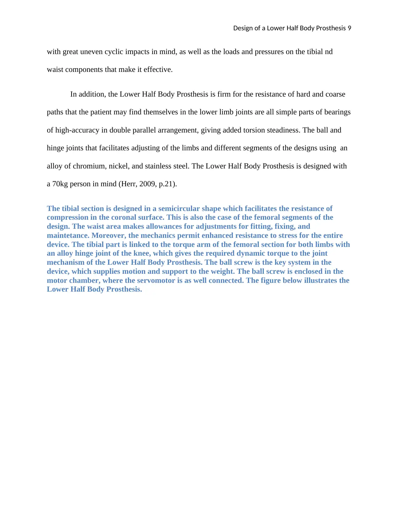
The tibial section is designed in a semicircular shape which facilitates the resistance of
compression in the coronal surface. This is also the case of the femoral segments of the
design. The waist area makes allowances for adjustments for fitting, fixing, and
maintetance. Moreover, the mechanics permit enhanced resistance to stress for the entire
device. The tibial part is linked to the torque arm of the femoral section for both limbs with
an alloy hinge joint of the knee, which gives the required dynamic torque to the joint
mechanism of the Lower Half Body Prosthesis. The ball screw is the key system in the
device, which supplies motion and support to the weight. The ball screw is enclosed in the
motor chamber, where the servomotor is as well connected. The figure below illustrates the
Lower Half Body Prosthesis.
with great uneven cyclic impacts in mind, as well as the loads and pressures on the tibial nd
waist components that make it effective.
In addition, the Lower Half Body Prosthesis is firm for the resistance of hard and coarse
paths that the patient may find themselves in the lower limb joints are all simple parts of bearings
of high-accuracy in double parallel arrangement, giving added torsion steadiness. The ball and
hinge joints that facilitates adjusting of the limbs and different segments of the designs using an
alloy of chromium, nickel, and stainless steel. The Lower Half Body Prosthesis is designed with
a 70kg person in mind (Herr, 2009, p.21).
The tibial section is designed in a semicircular shape which facilitates the resistance of
compression in the coronal surface. This is also the case of the femoral segments of the
design. The waist area makes allowances for adjustments for fitting, fixing, and
maintetance. Moreover, the mechanics permit enhanced resistance to stress for the entire
device. The tibial part is linked to the torque arm of the femoral section for both limbs with
an alloy hinge joint of the knee, which gives the required dynamic torque to the joint
mechanism of the Lower Half Body Prosthesis. The ball screw is the key system in the
device, which supplies motion and support to the weight. The ball screw is enclosed in the
motor chamber, where the servomotor is as well connected. The figure below illustrates the
Lower Half Body Prosthesis.
⊘ This is a preview!⊘
Do you want full access?
Subscribe today to unlock all pages.
Trusted by 1+ million students worldwide
Design of a Lower Half Body Prosthesis 10
Figure 1:Lower Half Body Prosthesis view:
The device is compact and light aiding in easy mobility of the user.
Figure 1:Lower Half Body Prosthesis view:
The device is compact and light aiding in easy mobility of the user.
Paraphrase This Document
Need a fresh take? Get an instant paraphrase of this document with our AI Paraphraser
Design of a Lower Half Body Prosthesis 11
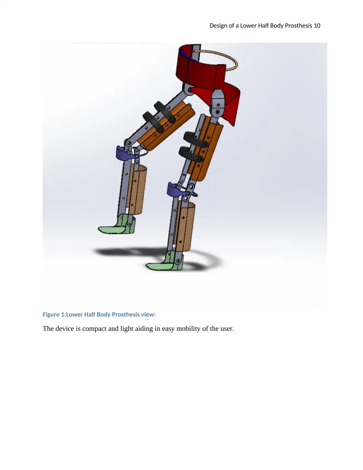
Figure 2 Prosthetic limbs and how it will operate
The figure below shows an intricate view of the Lower Half Body Prosthesis structure.
The prosthetic kneehas a total of 18 different and distinct screws, 12 bearings, and 13 separate
components.
Figure 2 Prosthetic limbs and how it will operate
The figure below shows an intricate view of the Lower Half Body Prosthesis structure.
The prosthetic kneehas a total of 18 different and distinct screws, 12 bearings, and 13 separate
components.
Design of a Lower Half Body Prosthesis 12
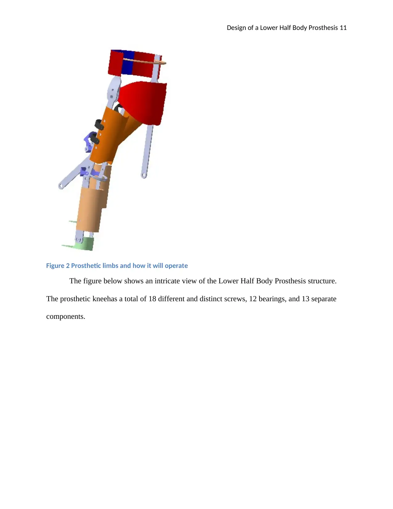
Figure 3 Front view of prosthesis to show the different components like screws, bearings, and
parts
Figure 3 Front view of prosthesis to show the different components like screws, bearings, and
parts
⊘ This is a preview!⊘
Do you want full access?
Subscribe today to unlock all pages.
Trusted by 1+ million students worldwide
1 out of 29
Your All-in-One AI-Powered Toolkit for Academic Success.
+13062052269
info@desklib.com
Available 24*7 on WhatsApp / Email
![[object Object]](/_next/static/media/star-bottom.7253800d.svg)
Unlock your academic potential
Copyright © 2020–2026 A2Z Services. All Rights Reserved. Developed and managed by ZUCOL.