PICAXE Dice Simulation: Design, Implementation, and Testing Project

Verified

Added on  2023/04/20

|11
|1256
|482
Project
AI Summary
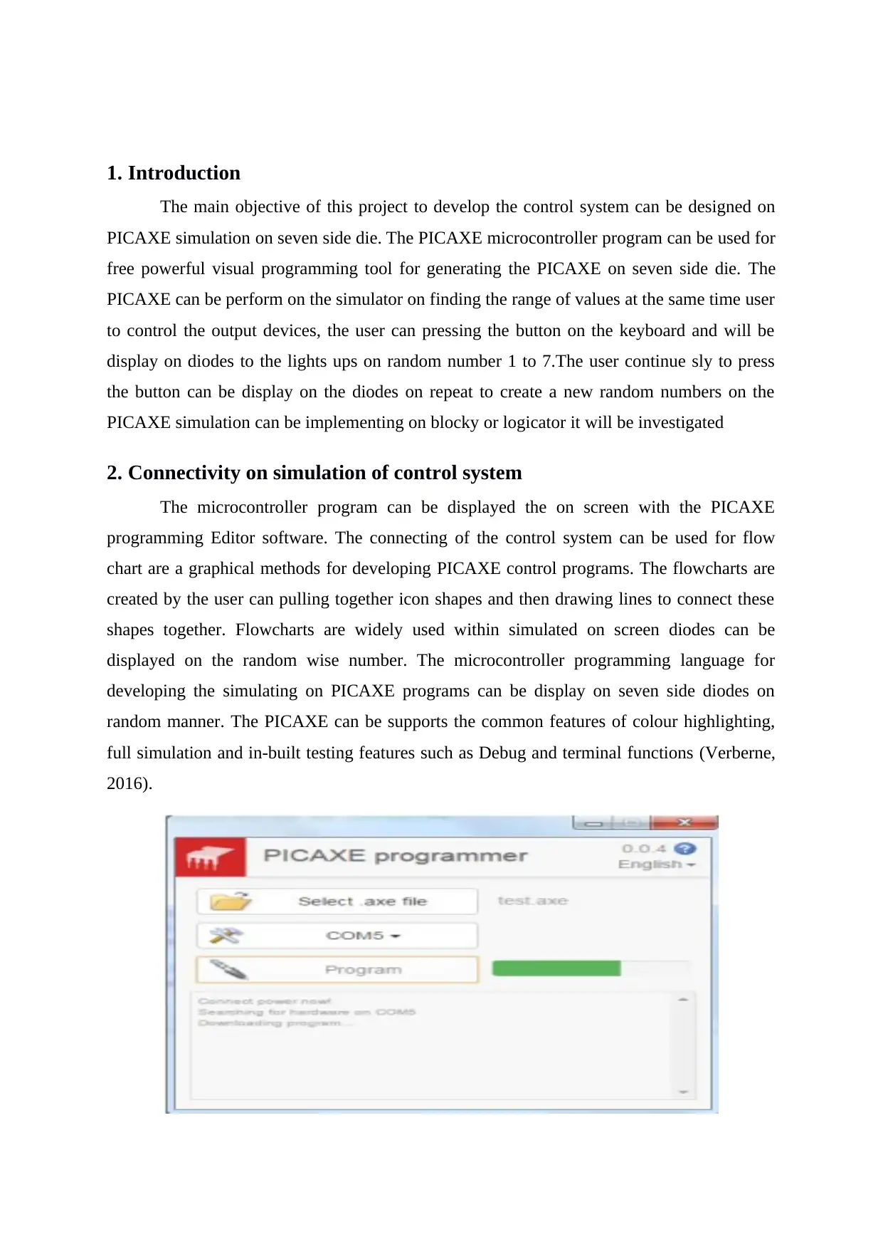
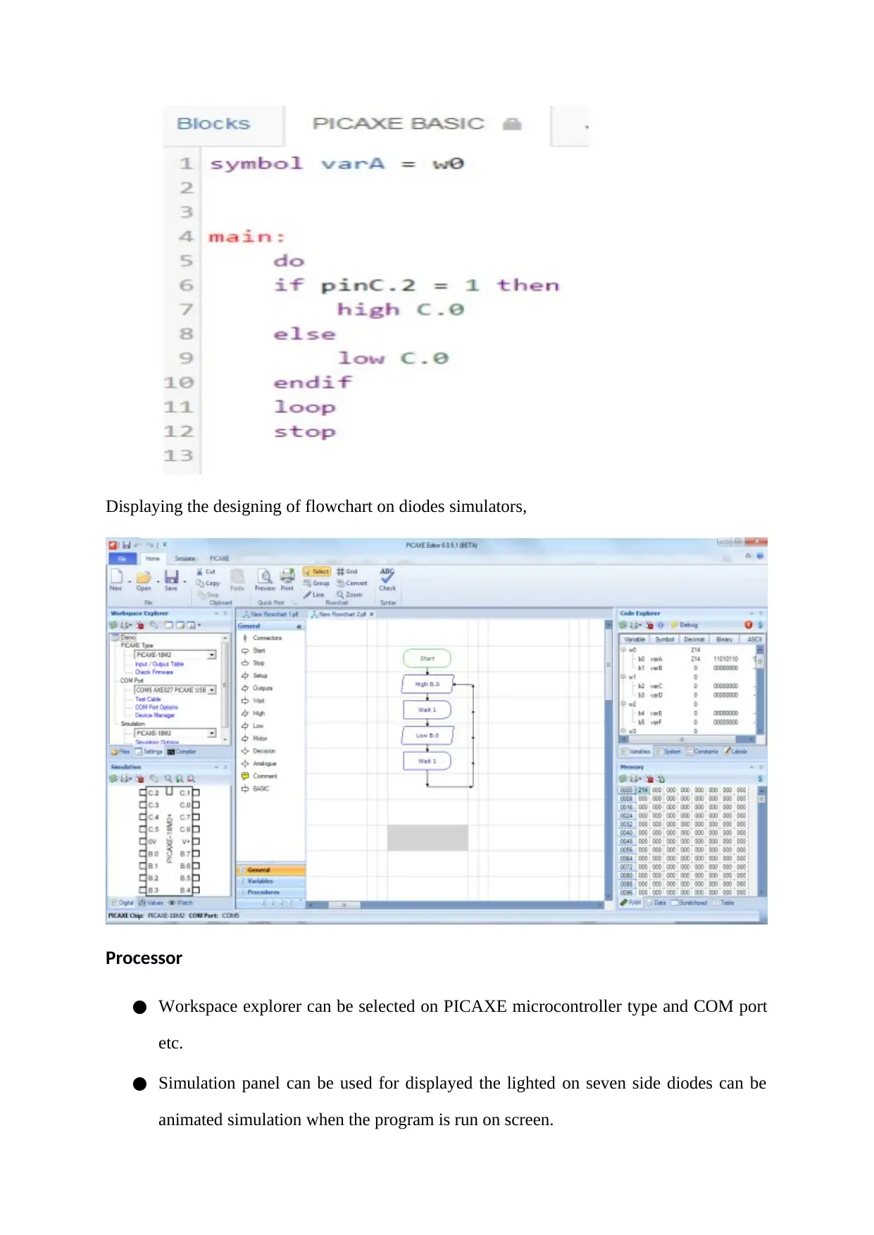
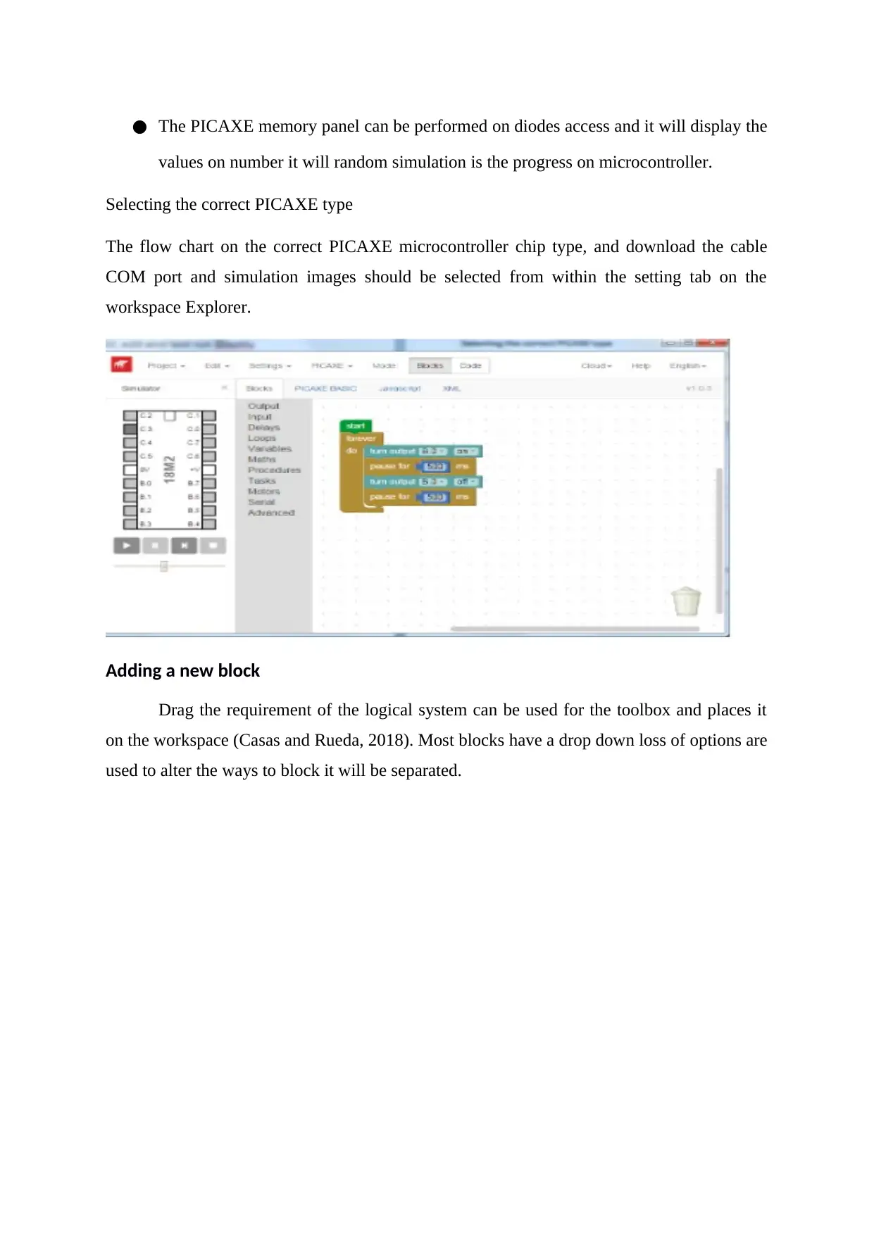
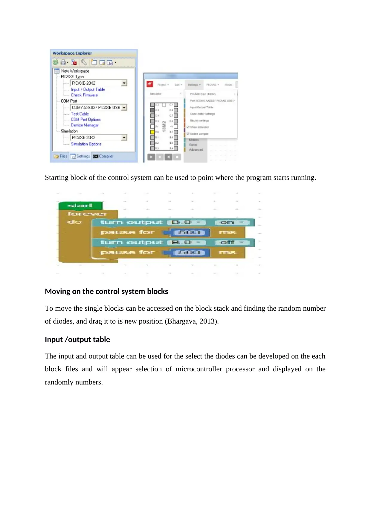
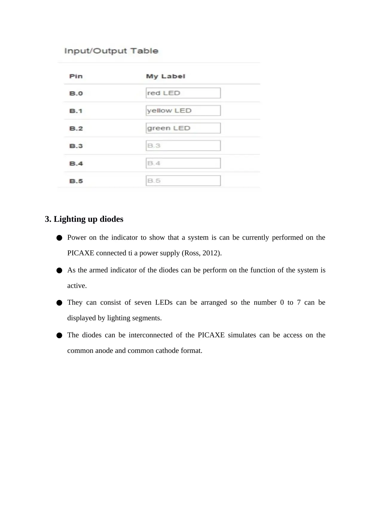
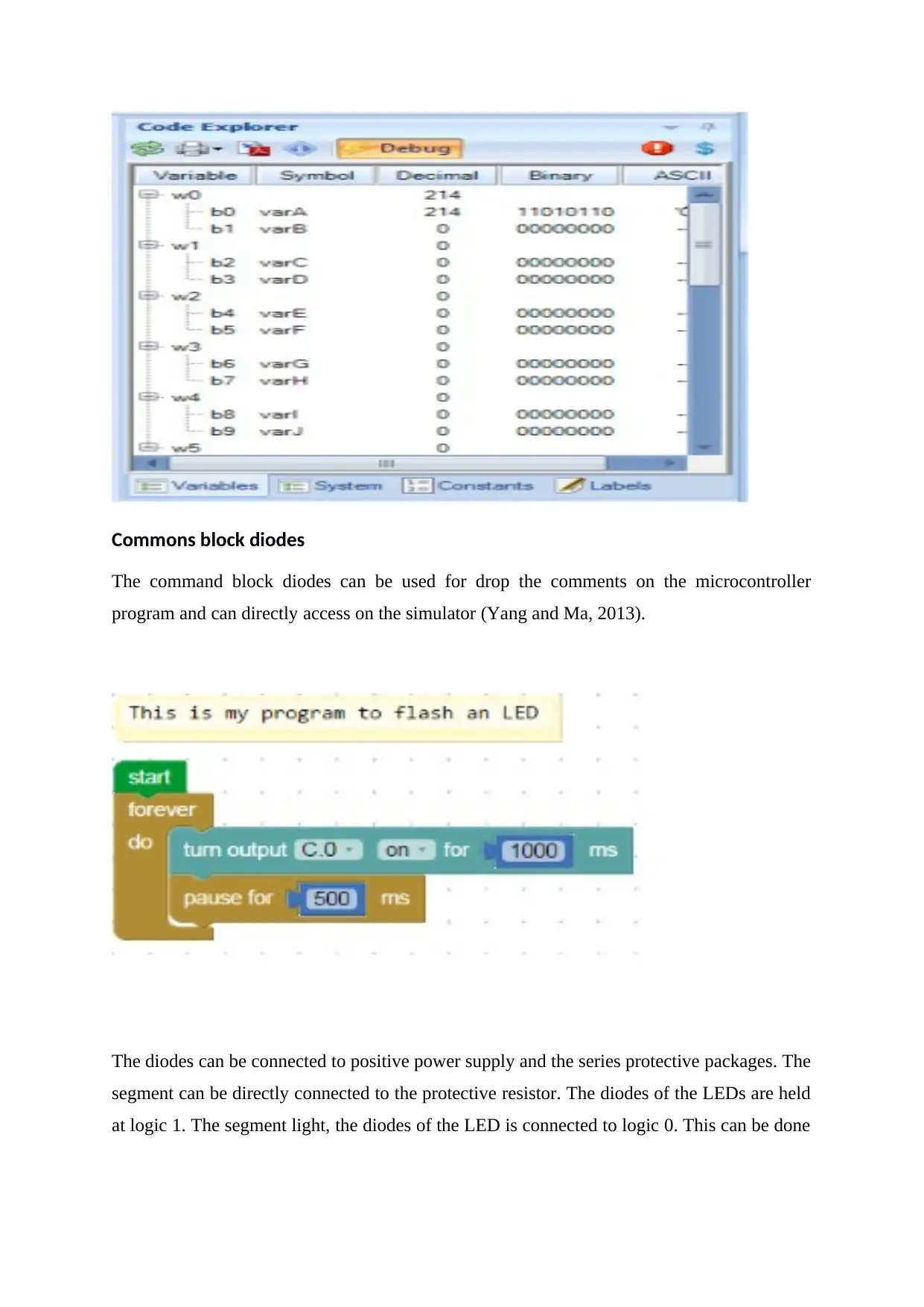
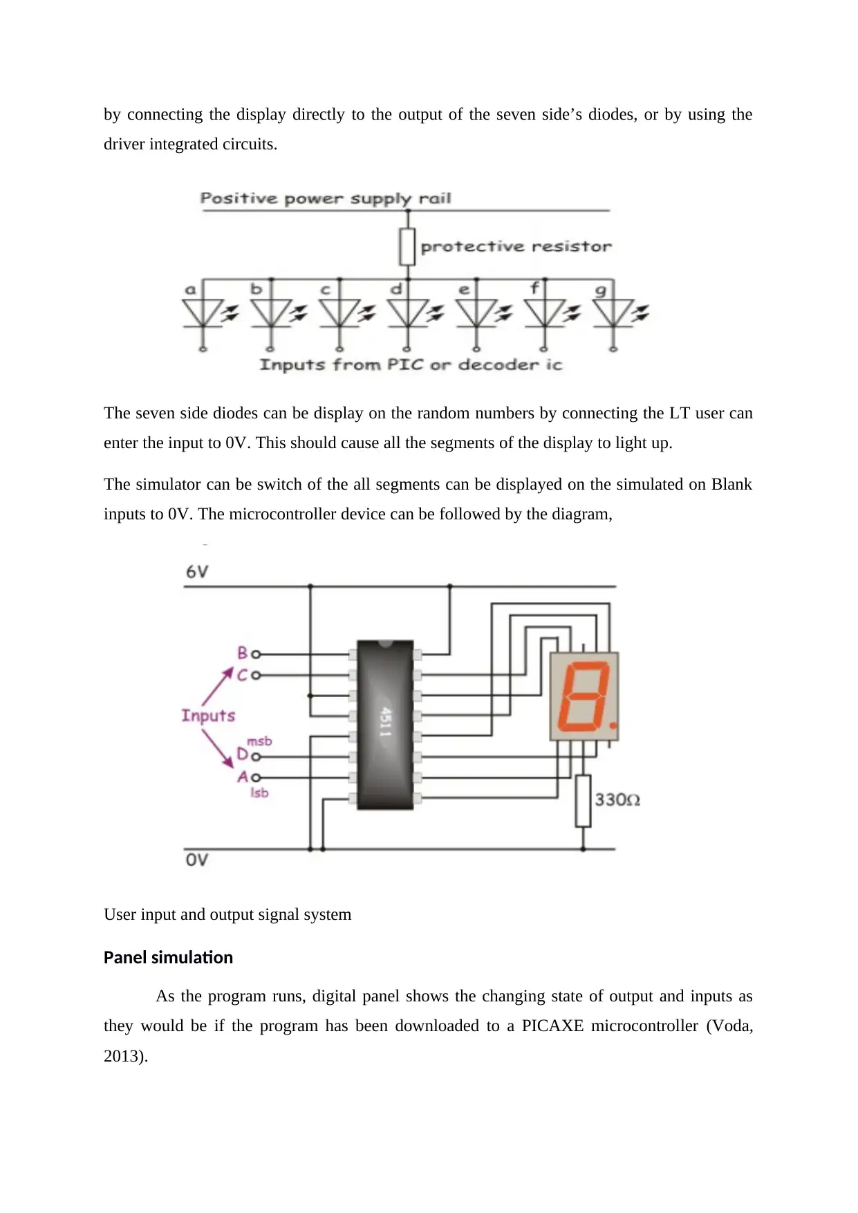
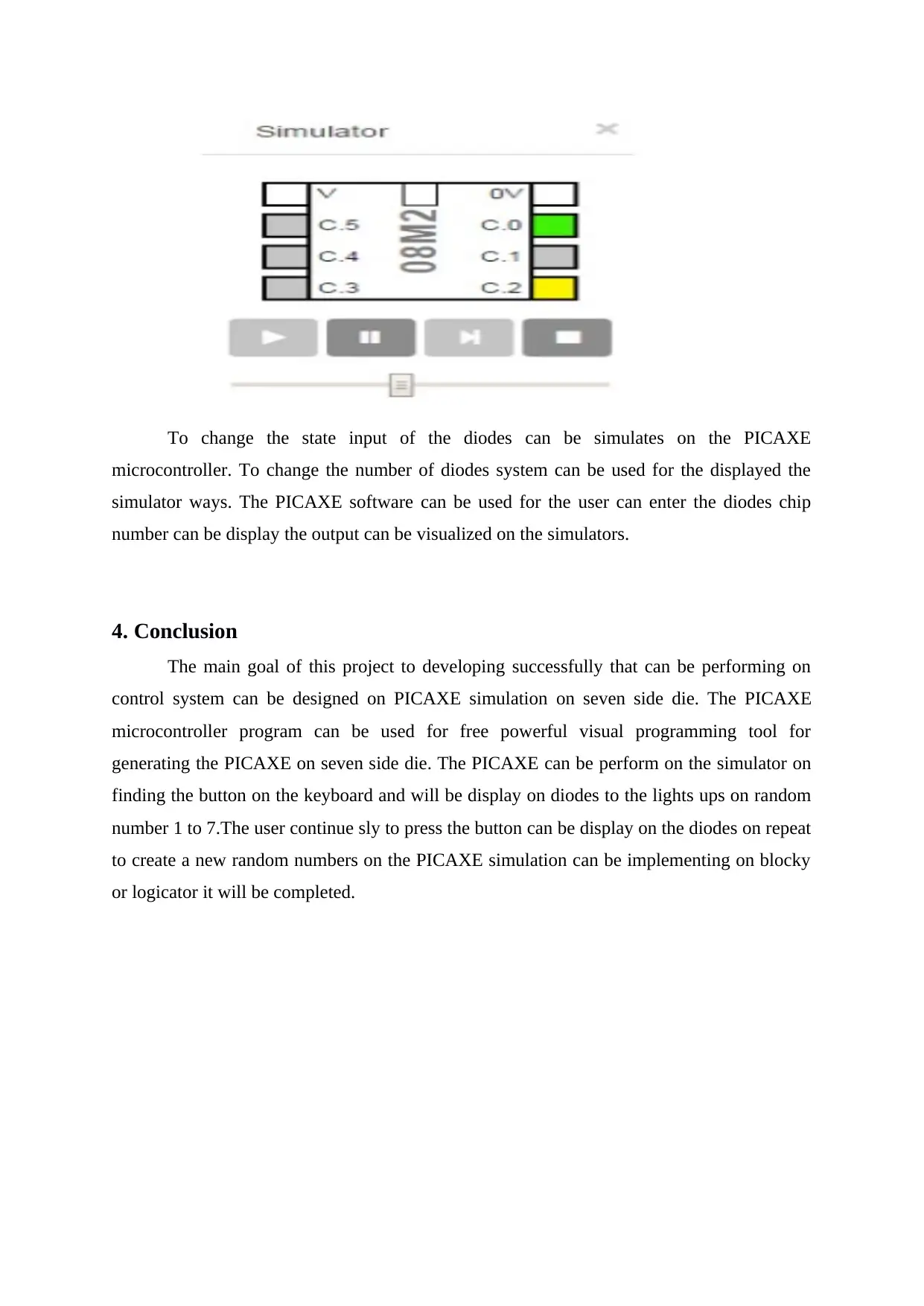
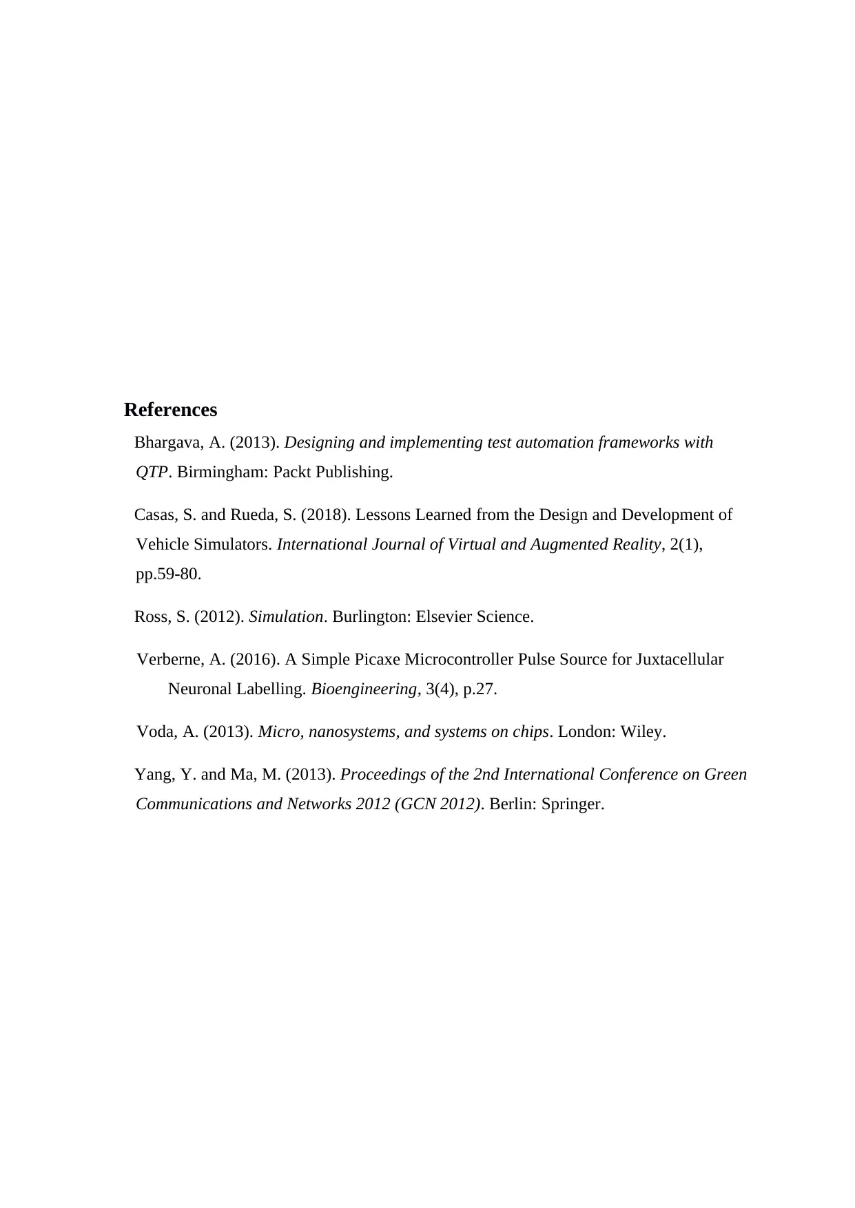
This project focuses on designing, implementing, and testing a control system using PICAXE simulation to create a seven-sided die. The project utilizes the PICAXE microcontroller program as a visual programming tool to generate random numbers from 1 to 7, displayed on seven side diodes. The user can initiate a new random number by pressing a button, with the simulation implemented using blocky or logicator programming. The document explains the connectivity of the control system, including the use of flowcharts and the PICAXE programming editor. It covers essential aspects such as selecting the correct PICAXE type, adding and moving blocks, utilizing input/output tables, and lighting up diodes in common anode and common cathode configurations. The simulation panel displays the changing states of inputs and outputs, mirroring a downloaded program on a PICAXE microcontroller, and concludes with a summary of the project's successful development and implementation.
Document Page
Design, Implement and Test a con
PICAXE dice simulation
tabler-icon-diamond-filled.svg

Paraphrase This Document

Need a fresh take? Get an instant paraphrase of this document with our AI Paraphraser
Document Page
Table of Contents
1. Introduction 2
2. Connectivity on simulation of control system 2
Processor 3
Adding a new block 4
Moving on the control system blocks 5
Input /output table 5
3. Lighting up diodes 6
Commons block diodes 7
Panel simulation 8
4. Conclusion 9
References 10
Document Page
1. Introduction
The main objective of this project to develop the control system can be designed on
PICAXE simulation on seven side die. The PICAXE microcontroller program can be used for
free powerful visual programming tool for generating the PICAXE on seven side die. The
PICAXE can be perform on the simulator on finding the range of values at the same time user
to control the output devices, the user can pressing the button on the keyboard and will be
display on diodes to the lights ups on random number 1 to 7.The user continue sly to press
the button can be display on the diodes on repeat to create a new random numbers on the
PICAXE simulation can be implementing on blocky or logicator it will be investigated
2. Connectivity on simulation of control system
The microcontroller program can be displayed the on screen with the PICAXE
programming Editor software. The connecting of the control system can be used for flow
chart are a graphical methods for developing PICAXE control programs. The flowcharts are
created by the user can pulling together icon shapes and then drawing lines to connect these
shapes together. Flowcharts are widely used within simulated on screen diodes can be
displayed on the random wise number. The microcontroller programming language for
developing the simulating on PICAXE programs can be display on seven side diodes on
random manner. The PICAXE can be supports the common features of colour highlighting,
full simulation and in-built testing features such as Debug and terminal functions (Verberne,
2016).
Document Page
Displaying the designing of flowchart on diodes simulators,
Processor
Workspace explorer can be selected on PICAXE microcontroller type and COM port
etc.
Simulation panel can be used for displayed the lighted on seven side diodes can be
animated simulation when the program is run on screen.
tabler-icon-diamond-filled.svg

Paraphrase This Document

Need a fresh take? Get an instant paraphrase of this document with our AI Paraphraser
Document Page
The PICAXE memory panel can be performed on diodes access and it will display the
values on number it will random simulation is the progress on microcontroller.
Selecting the correct PICAXE type
The flow chart on the correct PICAXE microcontroller chip type, and download the cable
COM port and simulation images should be selected from within the setting tab on the
workspace Explorer.
Adding a new block
Drag the requirement of the logical system can be used for the toolbox and places it
on the workspace (Casas and Rueda, 2018). Most blocks have a drop down loss of options are
used to alter the ways to block it will be separated.
Document Page
Starting block of the control system can be used to point where the program starts running.
Moving on the control system blocks
To move the single blocks can be accessed on the block stack and finding the random number
of diodes, and drag it to is new position (Bhargava, 2013).
Input /output table
The input and output table can be used for the select the diodes can be developed on the each
block files and will appear selection of microcontroller processor and displayed on the
randomly numbers.
Document Page
3. Lighting up diodes
Power on the indicator to show that a system is can be currently performed on the
PICAXE connected ti a power supply (Ross, 2012).
As the armed indicator of the diodes can be perform on the function of the system is
active.
They can consist of seven LEDs can be arranged so the number 0 to 7 can be
displayed by lighting segments.
The diodes can be interconnected of the PICAXE simulates can be access on the
common anode and common cathode format.
tabler-icon-diamond-filled.svg

Paraphrase This Document

Need a fresh take? Get an instant paraphrase of this document with our AI Paraphraser
Document Page
Commons block diodes
The command block diodes can be used for drop the comments on the microcontroller
program and can directly access on the simulator (Yang and Ma, 2013).
The diodes can be connected to positive power supply and the series protective packages. The
segment can be directly connected to the protective resistor. The diodes of the LEDs are held
at logic 1. The segment light, the diodes of the LED is connected to logic 0. This can be done
Document Page
by connecting the display directly to the output of the seven side’s diodes, or by using the
driver integrated circuits.
The seven side diodes can be display on the random numbers by connecting the LT user can
enter the input to 0V. This should cause all the segments of the display to light up.
The simulator can be switch of the all segments can be displayed on the simulated on Blank
inputs to 0V. The microcontroller device can be followed by the diagram,
User input and output signal system
Panel simulation
As the program runs, digital panel shows the changing state of output and inputs as
they would be if the program has been downloaded to a PICAXE microcontroller (Voda,
2013).
Document Page
To change the state input of the diodes can be simulates on the PICAXE
microcontroller. To change the number of diodes system can be used for the displayed the
simulator ways. The PICAXE software can be used for the user can enter the diodes chip
number can be display the output can be visualized on the simulators.
4. Conclusion
The main goal of this project to developing successfully that can be performing on
control system can be designed on PICAXE simulation on seven side die. The PICAXE
microcontroller program can be used for free powerful visual programming tool for
generating the PICAXE on seven side die. The PICAXE can be perform on the simulator on
finding the button on the keyboard and will be display on diodes to the lights ups on random
number 1 to 7.The user continue sly to press the button can be display on the diodes on repeat
to create a new random numbers on the PICAXE simulation can be implementing on blocky
or logicator it will be completed.
tabler-icon-diamond-filled.svg

Paraphrase This Document

Need a fresh take? Get an instant paraphrase of this document with our AI Paraphraser
Document Page
References
Bhargava, A. (2013). Designing and implementing test automation frameworks with
QTP. Birmingham: Packt Publishing.
Casas, S. and Rueda, S. (2018). Lessons Learned from the Design and Development of
Vehicle Simulators. International Journal of Virtual and Augmented Reality, 2(1),
pp.59-80.
Ross, S. (2012). Simulation. Burlington: Elsevier Science.
Verberne, A. (2016). A Simple Picaxe Microcontroller Pulse Source for Juxtacellular
Neuronal Labelling. Bioengineering, 3(4), p.27.
Voda, A. (2013). Micro, nanosystems, and systems on chips. London: Wiley.
Yang, Y. and Ma, M. (2013). Proceedings of the 2nd International Conference on Green
Communications and Networks 2012 (GCN 2012). Berlin: Springer.
chevron_up_icon
1 out of 11
circle_padding
hide_on_mobile
zoom_out_icon
[object Object]