Design Simulation Report: Cantilever Bracket Mechanical Analysis
VerifiedAdded on 2023/04/25
|12
|3003
|71
Report
AI Summary
This report presents a modeling and simulation study of a cantilever bracket using tools like SolidWorks to assess its mechanical performance against specified design criteria and optimize the component. The simulation involves applying a normal pressure of 5MPa to the top face of a 10mm thick alloy steel bracket, with one end fixed. The analysis covers stress distribution, displacement, and frequency, ensuring the design meets structural integrity requirements. The results indicate the stress levels are highest around the cut-out regions, with a maximum stress of 122MPa and a maximum displacement of 0.008mm. The report also discusses methods for optimizing the design by adjusting parameters, improving solve efficiency, and refining the shape to handle load conditions effectively. Experimental validation is recommended to ensure the simulation accurately models the physical system's behavior. The study confirms the SolidWorks model's ability to simulate the mechanical behavior of the cantilever bracket under load, providing valuable insights into its structural dynamics and potential optimizations. Desklib offers a wealth of similar solved assignments and past papers for students.
Modeling and Simulation
Name
Institution
Name
Institution
Paraphrase This Document
Need a fresh take? Get an instant paraphrase of this document with our AI Paraphraser

Executive Summary
Modeling and Simulation
Introduction
In the contemporary world, many research projects and industry applications have embraced and
adopted the use of development systems in the study and design of different systems, as it takes
advantage of modeling and simulation to understand the performance of these systems, and thus
their optimization for improvement. Modeling and simulation refers to the creation and analysis
of a digital prototype of a design model in order to allow for the prediction of the performance of
this prototype when it is used for its intended applications in the real world. In so doing,
simulation modeling can be very useful for scientist and engineers who seek to understand the
mechanical performance of a system in order to establish the chances and conditions of failure,
by simulating the loads that the system can withstand (Hoogland, Karn, and Newhouse, 2010, p.
331). Simulation modeling has also found application in the fields of heat transfer and fluid flow
in the event that the mechanical performance of the system being designed will be affected by
either fluid flow or heat transfer. The simulation manages to assess the mechanical performance
of a system by making use of simulation software on the modeled digital prototype, such that the
loading conditions when the system is used for its intended purpose works remain within the
right range to predict any form of failure and thus prepare the system for these forces. For this
reason, simulation is specifically important for designing products in industry and validating
their structural integrity as it allows for the working conditions of the system to be simulated and
confirmed before the actual prototype is built (Ferreira, et al., 2013, p.42). This allows for the
optimization of the system design aspects like the mass, dimensions, volume, material type, and
cost, ensuring the system remains compatible with its intended purposes over time for an
increased effectiveness and precision in mechanical design.
The simulation process uses a digital prototype in either three dimensions or in planar form
which can be easily developed from a CAD tool. The CAD tool is then meshed in order to
identify the finite elements that will be used to model the variation of the conditions being
investigated on the digital prototype. Meshing is achieved through the use of algorithms which
break the entire design being simulated into a finite number of elements whose actual values for
each element can be easily calculated. The analysis of data for each of the finite element is done
considering the conditions being investigated, the constraints and the material used. The
boundary conditions greatly determine the distribution of the parameter we are interested in
within the system designed (Hoogland, Karn, and Newhouse, 2010, p. 331). The results obtained
are then used to make engineering decisions as may be required based on the goal of simulation.
Examples of software used in mechanical engineering design include ANSYS, MATLAB,
Solidworks, Anylogic, and the Autodesk framework, among others.
Objective
⊘ This is a preview!⊘
Do you want full access?
Subscribe today to unlock all pages.
Trusted by 1+ million students worldwide
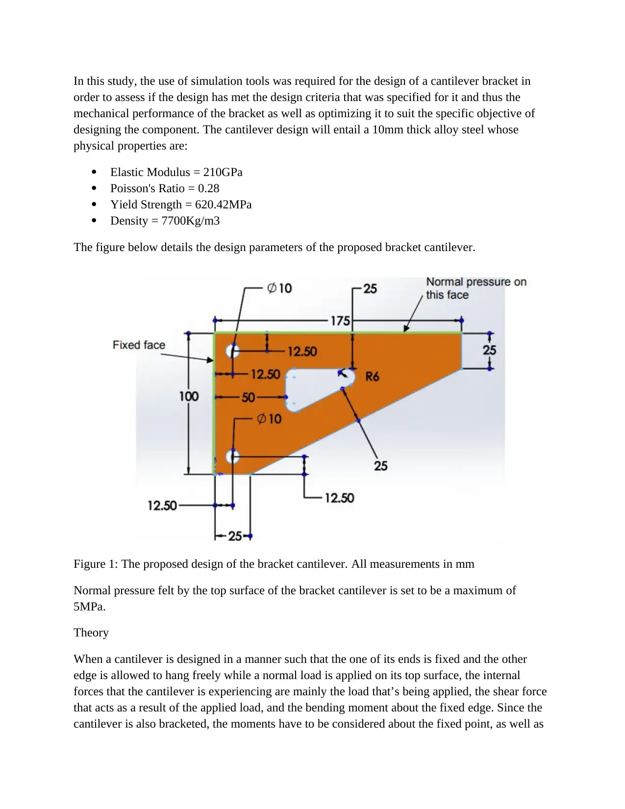
In this study, the use of simulation tools was required for the design of a cantilever bracket in
order to assess if the design has met the design criteria that was specified for it and thus the
mechanical performance of the bracket as well as optimizing it to suit the specific objective of
designing the component. The cantilever design will entail a 10mm thick alloy steel whose
physical properties are:
Elastic Modulus = 210GPa
Poisson's Ratio = 0.28
Yield Strength = 620.42MPa
Density = 7700Kg/m3
The figure below details the design parameters of the proposed bracket cantilever.
Figure 1: The proposed design of the bracket cantilever. All measurements in mm
Normal pressure felt by the top surface of the bracket cantilever is set to be a maximum of
5MPa.
Theory
When a cantilever is designed in a manner such that the one of its ends is fixed and the other
edge is allowed to hang freely while a normal load is applied on its top surface, the internal
forces that the cantilever is experiencing are mainly the load that’s being applied, the shear force
that acts as a result of the applied load, and the bending moment about the fixed edge. Since the
cantilever is also bracketed, the moments have to be considered about the fixed point, as well as
Paraphrase This Document
Need a fresh take? Get an instant paraphrase of this document with our AI Paraphraser
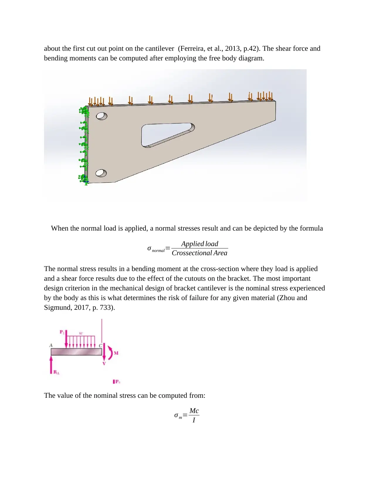
about the first cut out point on the cantilever (Ferreira, et al., 2013, p.42). The shear force and
bending moments can be computed after employing the free body diagram.
When the normal load is applied, a normal stresses result and can be depicted by the formula
σ normal= Applied load
Crossectional Area
The normal stress results in a bending moment at the cross-section where they load is applied
and a shear force results due to the effect of the cutouts on the bracket. The most important
design criterion in the mechanical design of bracket cantilever is the nominal stress experienced
by the body as this is what determines the risk of failure for any given material (Zhou and
Sigmund, 2017, p. 733).
The value of the nominal stress can be computed from:
σ m= Mc
I
σ x=−My
I
Where σ m= nominal stress
M= bending moment\
C(y)= maximum value of the displacement from the neutral surface
I=moment of inertia of the cross-section with respect to an axis
The total normal force causing compression and tension at different sections of bracket
cantilever can be estimated using the below expression.
FN =∫
0
ymax
My
I t . dy
Where: y= maximum value of the displacement (distance) from the neutral axis surface
Fn= normal forces caused by the stresses
M= bending moments
T=thickness of the cantilever section
I=moment of inertia of the cross-section with respect to an axis
(Coffman,et al., 2014, p. 17)
This expression has to model for the thickness of each aspect of the bracketed cantilever. This
explains the need for using the simulation as it automatically computes these forces for each
element meshed by the simulation software.
Methodology
The geometry of the bracket cantilever to be simulated was first modeled on a CAD tool in order
for the prototype being designed to be digitized or turned into the virtual formed. The dimensions
and orientation of the design were set in a manner that would allow the meshing process to be
simplified. During meshing the boundary conditions of the bracket cantilever were set, including
the normal applied load of 5MPa on the top surface of the bracket cantilever to be simulated.
This stage also entailed setting one end of the cantilever design to be fixed in order to allow for
the loading conditions of the digital prototype to be easily and correctly simulated. The meshes
were then generated. In the next stage, the loading conditions of the simulations were set as well
the material and material characteristics of the design were selected (Zhou and Sigmund, 2017,
p. 733). The set conditions on the simulation software were then run for the loading conditions to
⊘ This is a preview!⊘
Do you want full access?
Subscribe today to unlock all pages.
Trusted by 1+ million students worldwide
be simulated. The results generated are detailed in the results section and later discussed under
the discussion section of the report.
The simulation conditions were modeled such that the strength of the material the cantilever
bracket will be higher than the stresses and strains achieved during the loading process and thus
guaranteeing that failure will not occur.
Results
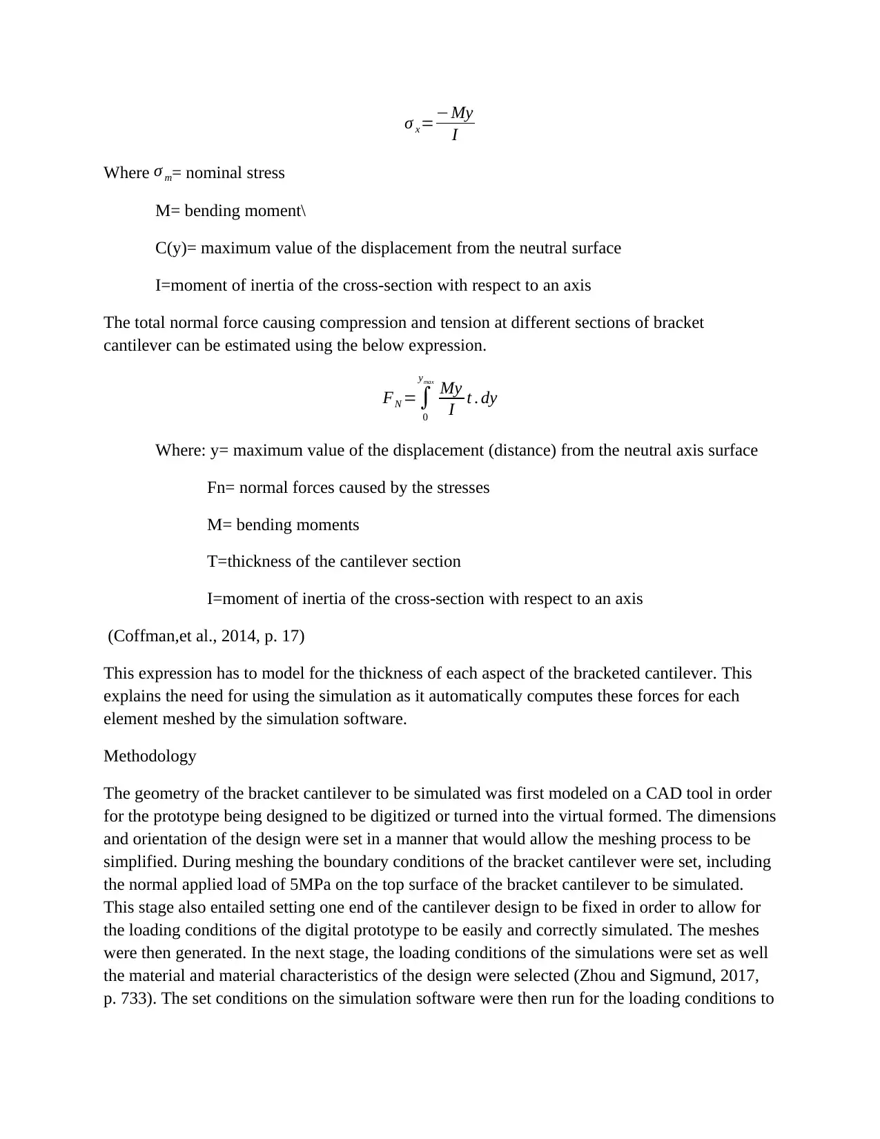
STATIC ANALYSIS OF BRACKET
Boundary condition
pressur
e of 5MPAid applied on top face , and left face is fixed in all six direction
Results
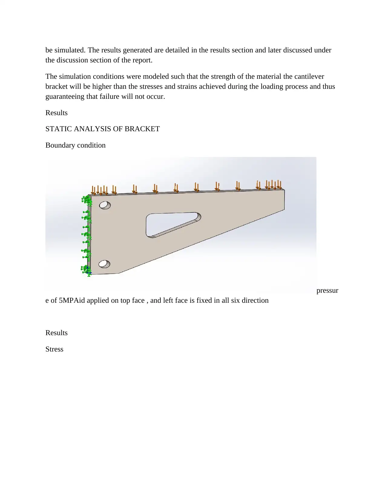
Stress
the discussion section of the report.
The simulation conditions were modeled such that the strength of the material the cantilever
bracket will be higher than the stresses and strains achieved during the loading process and thus
guaranteeing that failure will not occur.
Results
STATIC ANALYSIS OF BRACKET
Boundary condition
pressur
e of 5MPAid applied on top face , and left face is fixed in all six direction
Results
Stress
Paraphrase This Document
Need a fresh take? Get an instant paraphrase of this document with our AI Paraphraser
The stress conditions simulated in this software were able to show that the stress levels in the
bracket cantilever will be distributed according to the above figure (Wang, Yang,and Wu, et al.,
2009, p. 870). The areas experiencing the highest stresses when the cantilever bar is normally
loaded by a force of 5MPa on the top face of the bracket were those that border the cut out
regions and that the highest stress achieved in the bracket was 122MPa
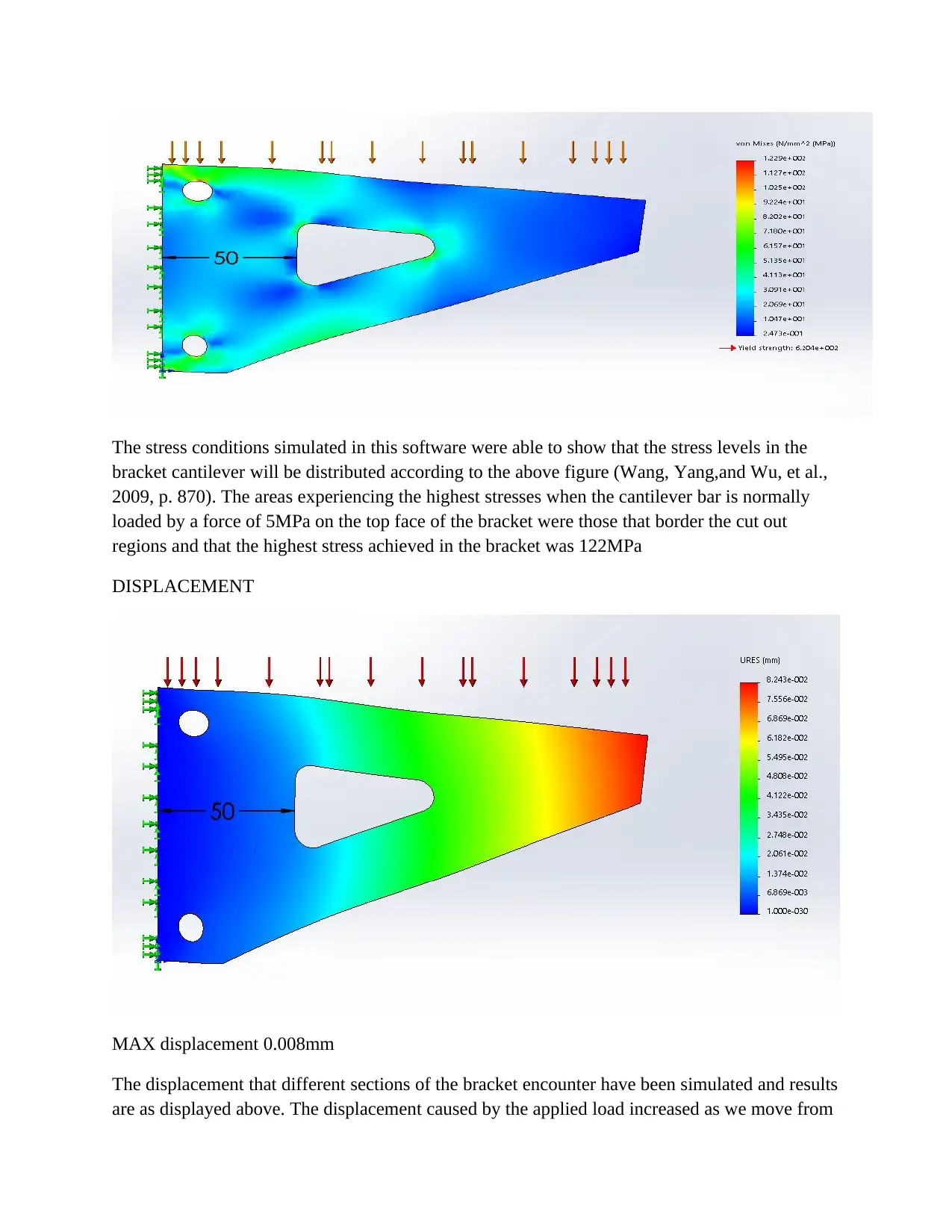
DISPLACEMENT
MAX displacement 0.008mm
The displacement that different sections of the bracket encounter have been simulated and results
are as displayed above. The displacement caused by the applied load increased as we move from
bracket cantilever will be distributed according to the above figure (Wang, Yang,and Wu, et al.,
2009, p. 870). The areas experiencing the highest stresses when the cantilever bar is normally
loaded by a force of 5MPa on the top face of the bracket were those that border the cut out
regions and that the highest stress achieved in the bracket was 122MPa
DISPLACEMENT
MAX displacement 0.008mm
The displacement that different sections of the bracket encounter have been simulated and results
are as displayed above. The displacement caused by the applied load increased as we move from
the fixed point of the bracket cantilever. The highest displacement level on the bracket was noted
at the furthest edge from the fixed edge and this is because there is less effect of moments
resisting the effect of the applied load at the edge that’s furthest from the fixed point.
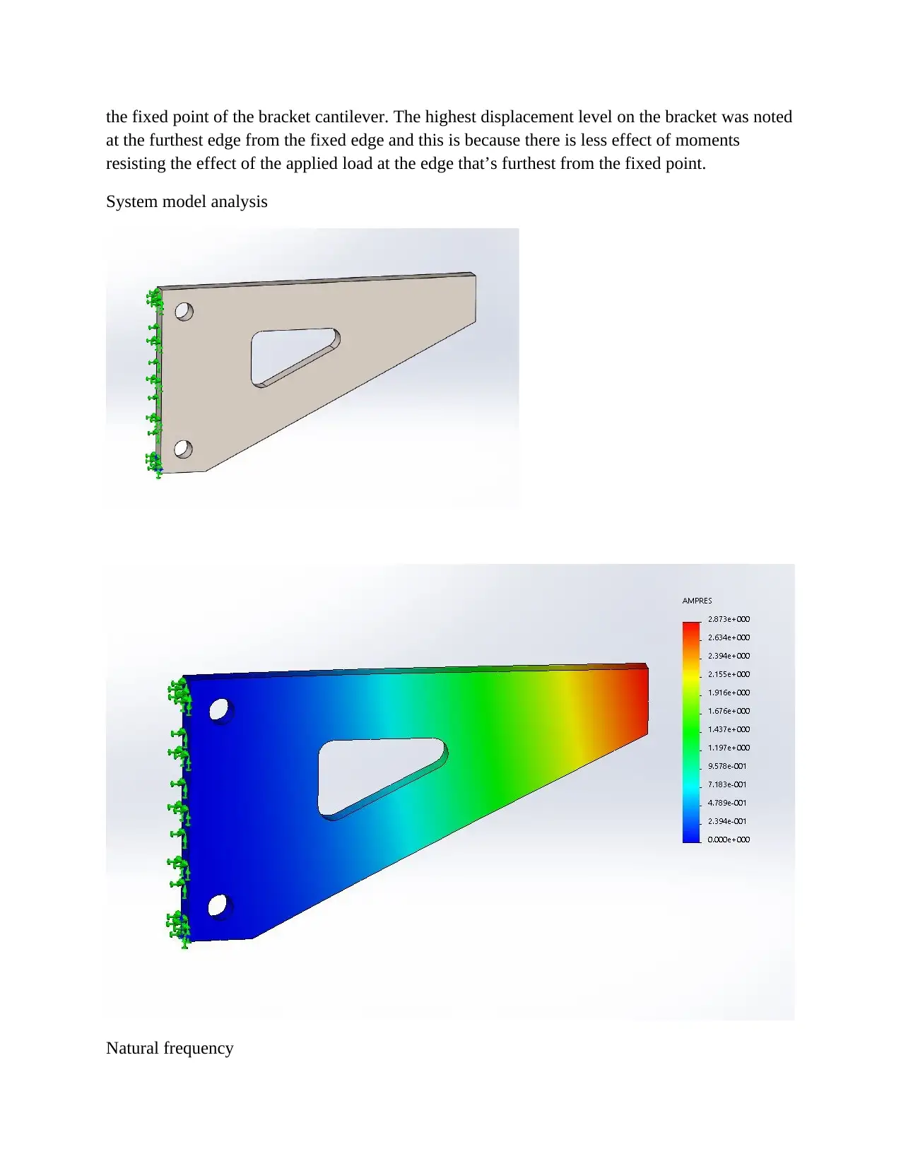
System model analysis
Natural frequency
at the furthest edge from the fixed edge and this is because there is less effect of moments
resisting the effect of the applied load at the edge that’s furthest from the fixed point.
System model analysis
Natural frequency
⊘ This is a preview!⊘
Do you want full access?
Subscribe today to unlock all pages.
Trusted by 1+ million students worldwide
Mode
No.
Frequency(Rad/
sec)
Frequency(Her
tz) Period(Seconds)
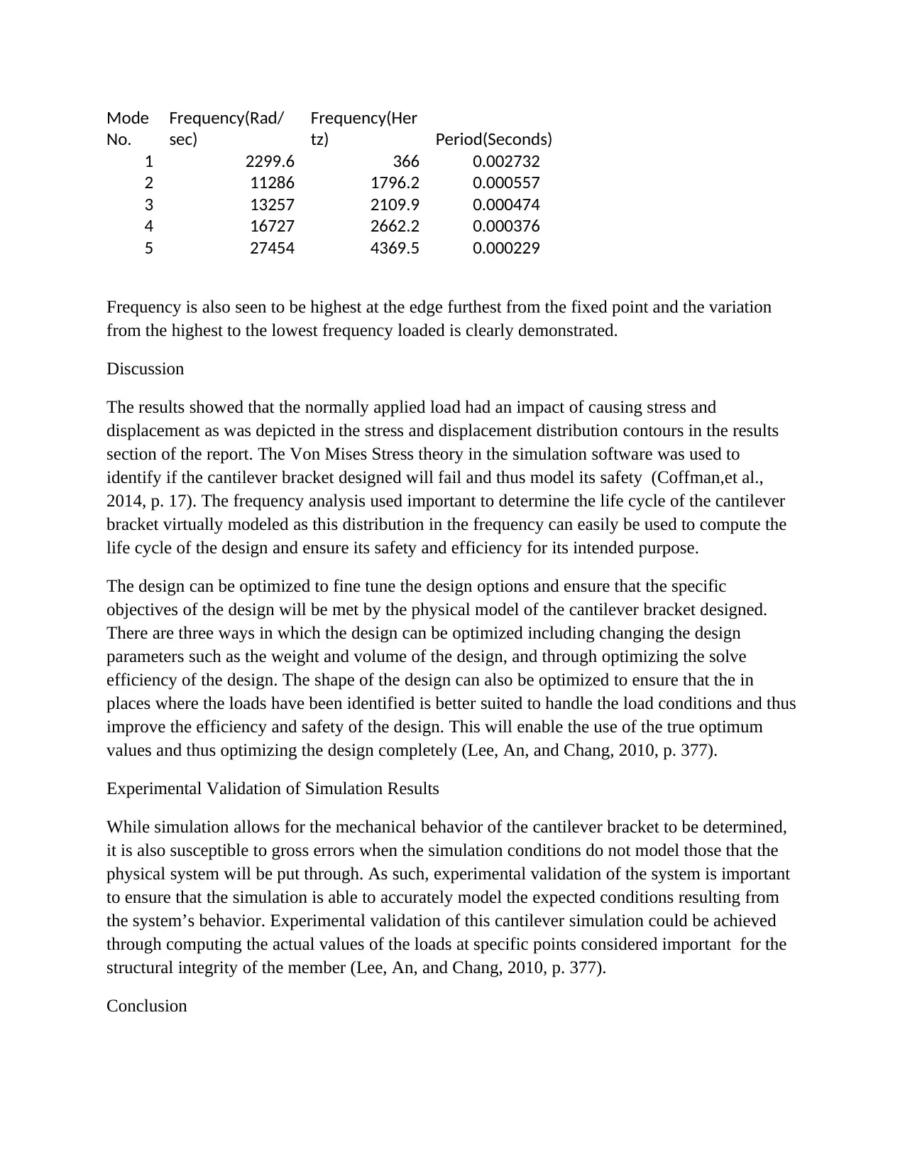
1 2299.6 366 0.002732
2 11286 1796.2 0.000557
3 13257 2109.9 0.000474
4 16727 2662.2 0.000376
5 27454 4369.5 0.000229
Frequency is also seen to be highest at the edge furthest from the fixed point and the variation
from the highest to the lowest frequency loaded is clearly demonstrated.
Discussion
The results showed that the normally applied load had an impact of causing stress and
displacement as was depicted in the stress and displacement distribution contours in the results
section of the report. The Von Mises Stress theory in the simulation software was used to
identify if the cantilever bracket designed will fail and thus model its safety (Coffman,et al.,
2014, p. 17). The frequency analysis used important to determine the life cycle of the cantilever
bracket virtually modeled as this distribution in the frequency can easily be used to compute the
life cycle of the design and ensure its safety and efficiency for its intended purpose.
The design can be optimized to fine tune the design options and ensure that the specific
objectives of the design will be met by the physical model of the cantilever bracket designed.
There are three ways in which the design can be optimized including changing the design
parameters such as the weight and volume of the design, and through optimizing the solve
efficiency of the design. The shape of the design can also be optimized to ensure that the in
places where the loads have been identified is better suited to handle the load conditions and thus
improve the efficiency and safety of the design. This will enable the use of the true optimum
values and thus optimizing the design completely (Lee, An, and Chang, 2010, p. 377).
Experimental Validation of Simulation Results
While simulation allows for the mechanical behavior of the cantilever bracket to be determined,
it is also susceptible to gross errors when the simulation conditions do not model those that the
physical system will be put through. As such, experimental validation of the system is important
to ensure that the simulation is able to accurately model the expected conditions resulting from
the system’s behavior. Experimental validation of this cantilever simulation could be achieved
through computing the actual values of the loads at specific points considered important for the
structural integrity of the member (Lee, An, and Chang, 2010, p. 377).
Conclusion
No.
Frequency(Rad/
sec)
Frequency(Her
tz) Period(Seconds)
1 2299.6 366 0.002732
2 11286 1796.2 0.000557
3 13257 2109.9 0.000474
4 16727 2662.2 0.000376
5 27454 4369.5 0.000229
Frequency is also seen to be highest at the edge furthest from the fixed point and the variation
from the highest to the lowest frequency loaded is clearly demonstrated.
Discussion
The results showed that the normally applied load had an impact of causing stress and
displacement as was depicted in the stress and displacement distribution contours in the results
section of the report. The Von Mises Stress theory in the simulation software was used to
identify if the cantilever bracket designed will fail and thus model its safety (Coffman,et al.,
2014, p. 17). The frequency analysis used important to determine the life cycle of the cantilever
bracket virtually modeled as this distribution in the frequency can easily be used to compute the
life cycle of the design and ensure its safety and efficiency for its intended purpose.
The design can be optimized to fine tune the design options and ensure that the specific
objectives of the design will be met by the physical model of the cantilever bracket designed.
There are three ways in which the design can be optimized including changing the design
parameters such as the weight and volume of the design, and through optimizing the solve
efficiency of the design. The shape of the design can also be optimized to ensure that the in
places where the loads have been identified is better suited to handle the load conditions and thus
improve the efficiency and safety of the design. This will enable the use of the true optimum
values and thus optimizing the design completely (Lee, An, and Chang, 2010, p. 377).
Experimental Validation of Simulation Results
While simulation allows for the mechanical behavior of the cantilever bracket to be determined,
it is also susceptible to gross errors when the simulation conditions do not model those that the
physical system will be put through. As such, experimental validation of the system is important
to ensure that the simulation is able to accurately model the expected conditions resulting from
the system’s behavior. Experimental validation of this cantilever simulation could be achieved
through computing the actual values of the loads at specific points considered important for the
structural integrity of the member (Lee, An, and Chang, 2010, p. 377).
Conclusion
Paraphrase This Document
Need a fresh take? Get an instant paraphrase of this document with our AI Paraphraser
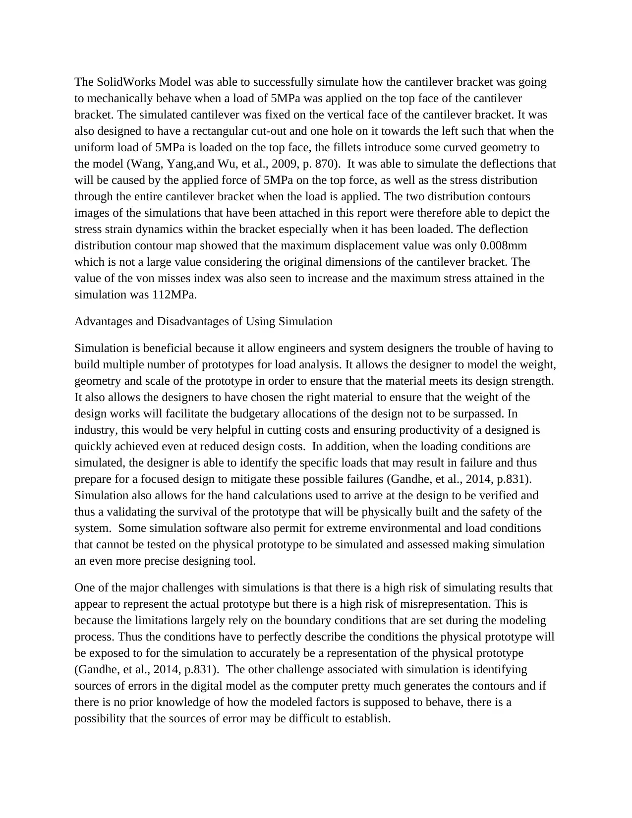
The SolidWorks Model was able to successfully simulate how the cantilever bracket was going
to mechanically behave when a load of 5MPa was applied on the top face of the cantilever
bracket. The simulated cantilever was fixed on the vertical face of the cantilever bracket. It was
also designed to have a rectangular cut-out and one hole on it towards the left such that when the
uniform load of 5MPa is loaded on the top face, the fillets introduce some curved geometry to
the model (Wang, Yang,and Wu, et al., 2009, p. 870). It was able to simulate the deflections that
will be caused by the applied force of 5MPa on the top force, as well as the stress distribution
through the entire cantilever bracket when the load is applied. The two distribution contours
images of the simulations that have been attached in this report were therefore able to depict the
stress strain dynamics within the bracket especially when it has been loaded. The deflection
distribution contour map showed that the maximum displacement value was only 0.008mm
which is not a large value considering the original dimensions of the cantilever bracket. The
value of the von misses index was also seen to increase and the maximum stress attained in the
simulation was 112MPa.
Advantages and Disadvantages of Using Simulation
Simulation is beneficial because it allow engineers and system designers the trouble of having to
build multiple number of prototypes for load analysis. It allows the designer to model the weight,
geometry and scale of the prototype in order to ensure that the material meets its design strength.
It also allows the designers to have chosen the right material to ensure that the weight of the
design works will facilitate the budgetary allocations of the design not to be surpassed. In
industry, this would be very helpful in cutting costs and ensuring productivity of a designed is
quickly achieved even at reduced design costs. In addition, when the loading conditions are
simulated, the designer is able to identify the specific loads that may result in failure and thus
prepare for a focused design to mitigate these possible failures (Gandhe, et al., 2014, p.831).
Simulation also allows for the hand calculations used to arrive at the design to be verified and
thus a validating the survival of the prototype that will be physically built and the safety of the
system. Some simulation software also permit for extreme environmental and load conditions
that cannot be tested on the physical prototype to be simulated and assessed making simulation
an even more precise designing tool.
One of the major challenges with simulations is that there is a high risk of simulating results that
appear to represent the actual prototype but there is a high risk of misrepresentation. This is
because the limitations largely rely on the boundary conditions that are set during the modeling
process. Thus the conditions have to perfectly describe the conditions the physical prototype will
be exposed to for the simulation to accurately be a representation of the physical prototype
(Gandhe, et al., 2014, p.831). The other challenge associated with simulation is identifying
sources of errors in the digital model as the computer pretty much generates the contours and if
there is no prior knowledge of how the modeled factors is supposed to behave, there is a
possibility that the sources of error may be difficult to establish.
In the industrial case, simulations have found wide applications in the design and have brought
advantages such as significant reductions in the design budget and thus improving the overall
productivity of the design. Simulations have also allowed industry designers to study the
behavior of systems without building them thus reducing the timeframe it takes to find the
unexpected phenomenon in the system that could cause failure (Wang, Yang,and Wu, et al.,
2009, p. 870). However, the industry presents a challenge as industrial simulations of designs
that are being developed may be difficult to interpret as their meaning could be yet to be
understood or interpreted.
References
Hoogland, T.A., Karn, E.L. and Newhouse, T.J., Herman Miller Inc. (2010). Cantilever bracket
assembly. U.S. Patent 6,019,331.
Ferreira, W.G., Martins, F., Kameoka, S., Salloum, A.S. and Kaeya, J.T., (2013). Structural optimization
of automotive components applied to durability problems. SAE Technical Paper 5(3) pp. 41-49.
Zhou, M. and Sigmund, O., (2017). On fully stressed design and p-norm measures in structural
optimization. Structural and Multidisciplinary Optimization, 56(3), pp.731-736.
Coffman, J., Terdalkar, S.S., Rencis, J.J. and Brown, A.O., (2014). Integrating Fatigue Analysis into a
Machine Design Course or Finite Element Course. In CD-ROM Proceedings of the American Society for
Engineering Education (ASEE) Midwest Section Conference (pp. 17-19).
Lee, J.S., An, Y.N. and Chang, K., (2010, October). Optimum structural design based on isogeometric
analysis method. In International Forum on Strategic Technology 2010 (pp. 377-381). IEEE.
Wang, J.X., Yang, X. and Yu, X.J., (2009). Nonlinear finite element analysis and test of lateral loading
for two-post ROPS. In Applied Mechanics and Materials (Vol. 16, pp. 866-870). Trans Tech
Publications.
Gandhe, G.V., Sural, V., Pastrick, T. and Hoelscher, K., (2014). Side Mirror Quality Improvement-
Design Philosophy and Computer Aided Engineering Approach. SAE transactions, pp.831-835.
⊘ This is a preview!⊘
Do you want full access?
Subscribe today to unlock all pages.
Trusted by 1+ million students worldwide
1 out of 12
Related Documents


Your All-in-One AI-Powered Toolkit for Academic Success.
+13062052269
info@desklib.com
Available 24*7 on WhatsApp / Email
![[object Object]](/_next/static/media/star-bottom.7253800d.svg)
Unlock your academic potential
Copyright © 2020–2026 A2Z Services. All Rights Reserved. Developed and managed by ZUCOL.