PV System Design & Battery Storage for Residential Home Energy
VerifiedAdded on 2023/06/12
|27
|5895
|265
Project
AI Summary
This project report outlines the design of a 5kW photovoltaic (PV) system with battery energy storage for a residential home, aiming to provide a reliable and environmentally friendly energy solution. The system comprises 15-20 solar panels, a 21.6 kWh battery bank, and a 6.8 kWh generator. The report details the energy flow within the system, including PV charge controller losses and battery round-trip efficiency. It also compares the capital costs of the solar system with traditional generators, addressing the economic and environmental aspects of the design. The methodology includes modeling energy components, mathematical cost analysis, and computer simulation to optimize the system's performance and cost-effectiveness. The analysis considers factors such as energy demand, component sizing, and the integration of renewable energy sources to ensure a sustainable and efficient energy supply for the household. Desklib provides a platform to access this and similar solved assignments.
Designing a PV system with battery as energy storage device1
DESIGNING OF PV SYSTEM WITH BATTERIES AS THE ENERGY STORAGE IN
THE RESIDENTIAL HOME.
By Name
Course
Instructor
Institution
Location
Date
DESIGNING OF PV SYSTEM WITH BATTERIES AS THE ENERGY STORAGE IN
THE RESIDENTIAL HOME.
By Name
Course
Instructor
Institution
Location
Date
Paraphrase This Document
Need a fresh take? Get an instant paraphrase of this document with our AI Paraphraser
Designing a PV system with battery as energy storage device2
ABSTRACT
This report gives an experience with the photovoltaic hybrid system as the better option to the
other forms of energy. This kind of system has been designed to curb the resent climate problems
and also ensuring the reliability of the energy supply without interferences. The designing of the
system also helps in the improvement of the efficiency of the system since it has been integrated
to the battery banks. This system has been designed to help in improving the simplicity thus
simulation tool that is conventional was used to in the representation of the data. The system of
5kW comprises of the PV solar panels of about 15-20 panels, battery worth 21.6 kWh and a
generator worth 6.8kWh.This report indicates the flow of the energy through the system, the PV
charge controller losses, the round strip of the battery and finally indicating how the capital cost
of the solar system is much higher than the use of the generators (Burton, 2011)
Designing a PV system with battery as energy storage device3
Contents
ABSTRACT................................................................................................................................................2
INTRODUCTION.......................................................................................................................................4
MODELS OF THE ENERGY.................................................................................................................4
Development of a model for the components of the energy system.....................................................5
METHODOLOGY......................................................................................................................................7
MATHEMATICAL COST OF THE MODEL........................................................................................8
COMPARISON OF THE COST OF THE CONNECTION OF THE GRID WITH THE SOLAR
SYSTEM.................................................................................................................................................8
The annual cost of the components......................................................................................................8
The annualized cost of replacement.....................................................................................................8
Annualized Operating Cost..................................................................................................................9
Emission cost.....................................................................................................................................10
Life cycle costing....................................................................................................................................11
Grid connection.....................................................................................................................................12
Sizing of the grid connected PV system................................................................................................12
TYPICAL POWER OUTPUT OF 4KW SOLAR SYSTEM.................................................................13
HOW THE COMPUTER SIMULATION WAS DESCRIBED................................................................14
DESCRIPTION OF THE SYSTEM..........................................................................................................14
Hybrid connection and other power sources..........................................................................................14
COST OF COMPONENTS AND THE LABOR...................................................................................14
RESULTS AND DISCUSSION................................................................................................................16
RESULT................................................................................................................................................16
The energy demand...........................................................................................................................17
DISCUSION..........................................................................................................................................18
CONCLUSION.........................................................................................................................................20
REFERENCES..........................................................................................................................................21
⊘ This is a preview!⊘
Do you want full access?
Subscribe today to unlock all pages.
Trusted by 1+ million students worldwide
Designing a PV system with battery as energy storage device4
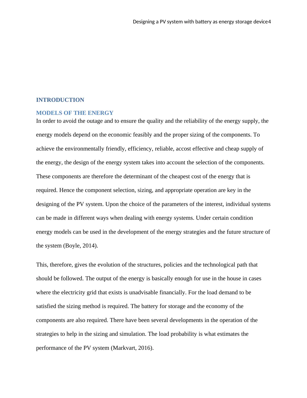
INTRODUCTION
MODELS OF THE ENERGY
In order to avoid the outage and to ensure the quality and the reliability of the energy supply, the
energy models depend on the economic feasibly and the proper sizing of the components. To
achieve the environmentally friendly, efficiency, reliable, accost effective and cheap supply of
the energy, the design of the energy system takes into account the selection of the components.
These components are therefore the determinant of the cheapest cost of the energy that is
required. Hence the component selection, sizing, and appropriate operation are key in the
designing of the PV system. Upon the choice of the parameters of the interest, individual systems
can be made in different ways when dealing with energy systems. Under certain condition
energy models can be used in the development of the energy strategies and the future structure of
the system (Boyle, 2014).
This, therefore, gives the evolution of the structures, policies and the technological path that
should be followed. The output of the energy is basically enough for use in the house in cases
where the electricity grid that exists is unadvisable financially. For the load demand to be
satisfied the sizing method is required. The battery for storage and the economy of the
components are also required. There have been several developments in the operation of the
strategies to help in the sizing and simulation. The load probability is what estimates the
performance of the PV system (Markvart, 2016).
Paraphrase This Document
Need a fresh take? Get an instant paraphrase of this document with our AI Paraphraser
Designing a PV system with battery as energy storage device5
Whoever, where the required weather data are available like the irrigation, temperature, humidity
and clearness index, the conventional method is to be used for the sizing of the PV system.
Therefore a good solution is provided by this method to help in the sizing of the PV system in
this particular area especially when the required data is not available. But for the operation of
these methods there has to be long-term metrological data research that indicates the nature of
the air temperature and the solar radiation in this particular area, Hence this method cannot be
used if the there is no proper metrological data research(Zhou,2010).
This method can also be used to determine the amount of the solar panels that can be used in the
operation and the tampon of the batteries that can also be used in the configuration. This method
has also been used to meet the reliability of the power and also to lower the cost of the energy
that is used at a given time. This model targets the development of the system with a component
that is cheaper giving low value on the cost of the energy. The method can also be used in the
determination of the number of the solar panel that can be used in the operation of this system
and the battery configuration that aids in the storage of the power (Cammarano, 2012).
Development of a model for the components of the energy system.
The essential step in this phase of the component sizing is the modeling. There various studies
that have been used in the development of the PV system model. For this PV system, there is two
various principles that is to be considered, they include, PV generators and the battery for the
storage. The method for modeling is described below as follows;
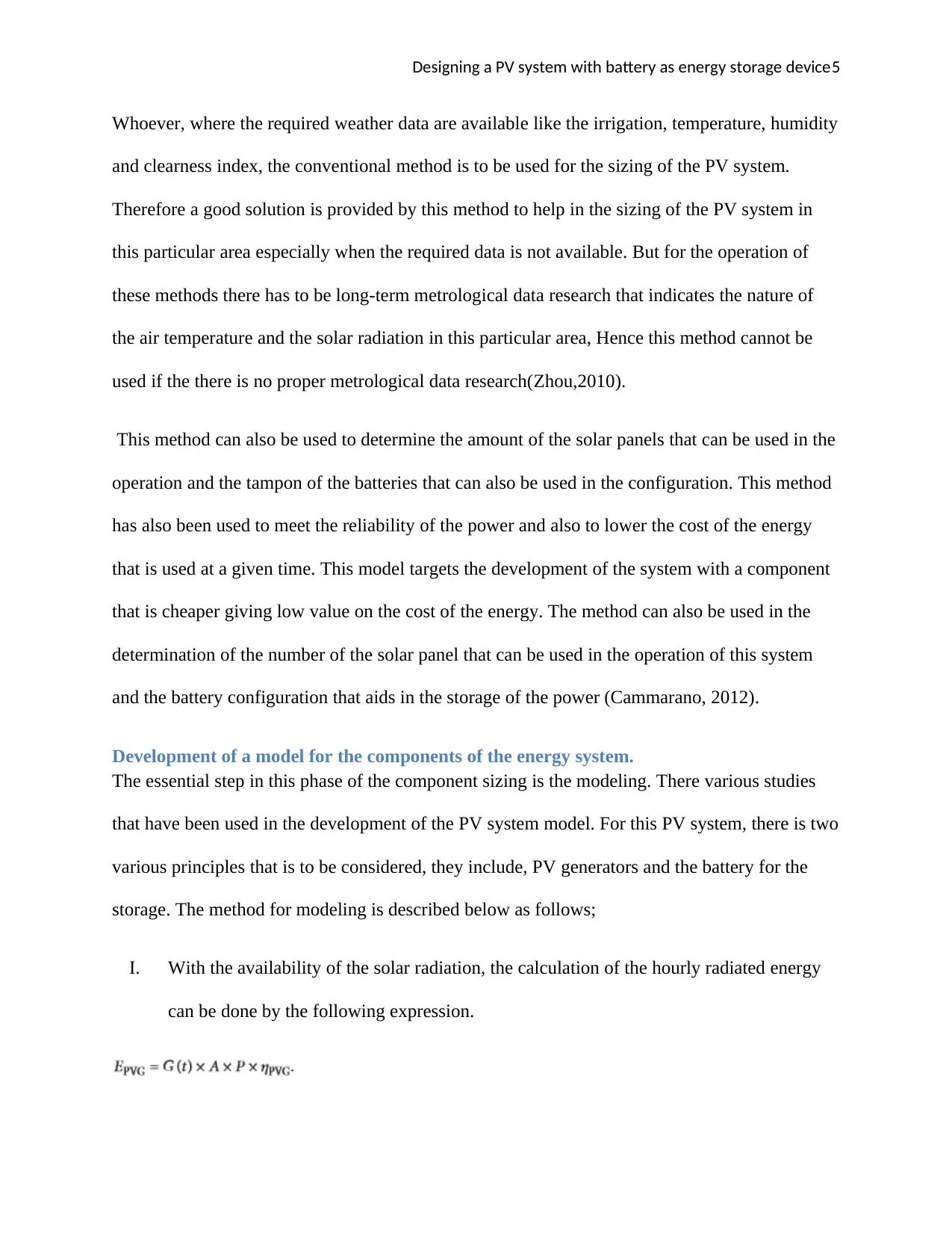
I. With the availability of the solar radiation, the calculation of the hourly radiated energy
can be done by the following expression.
Whoever, where the required weather data are available like the irrigation, temperature, humidity
and clearness index, the conventional method is to be used for the sizing of the PV system.
Therefore a good solution is provided by this method to help in the sizing of the PV system in
this particular area especially when the required data is not available. But for the operation of
these methods there has to be long-term metrological data research that indicates the nature of
the air temperature and the solar radiation in this particular area, Hence this method cannot be
used if the there is no proper metrological data research(Zhou,2010).
This method can also be used to determine the amount of the solar panels that can be used in the
operation and the tampon of the batteries that can also be used in the configuration. This method
has also been used to meet the reliability of the power and also to lower the cost of the energy
that is used at a given time. This model targets the development of the system with a component
that is cheaper giving low value on the cost of the energy. The method can also be used in the
determination of the number of the solar panel that can be used in the operation of this system
and the battery configuration that aids in the storage of the power (Cammarano, 2012).
Development of a model for the components of the energy system.
The essential step in this phase of the component sizing is the modeling. There various studies
that have been used in the development of the PV system model. For this PV system, there is two
various principles that is to be considered, they include, PV generators and the battery for the
storage. The method for modeling is described below as follows;
I. With the availability of the solar radiation, the calculation of the hourly radiated energy
can be done by the following expression.
Designing a PV system with battery as energy storage device6
This expression gives the modeling of the solar photovoltaic generator.
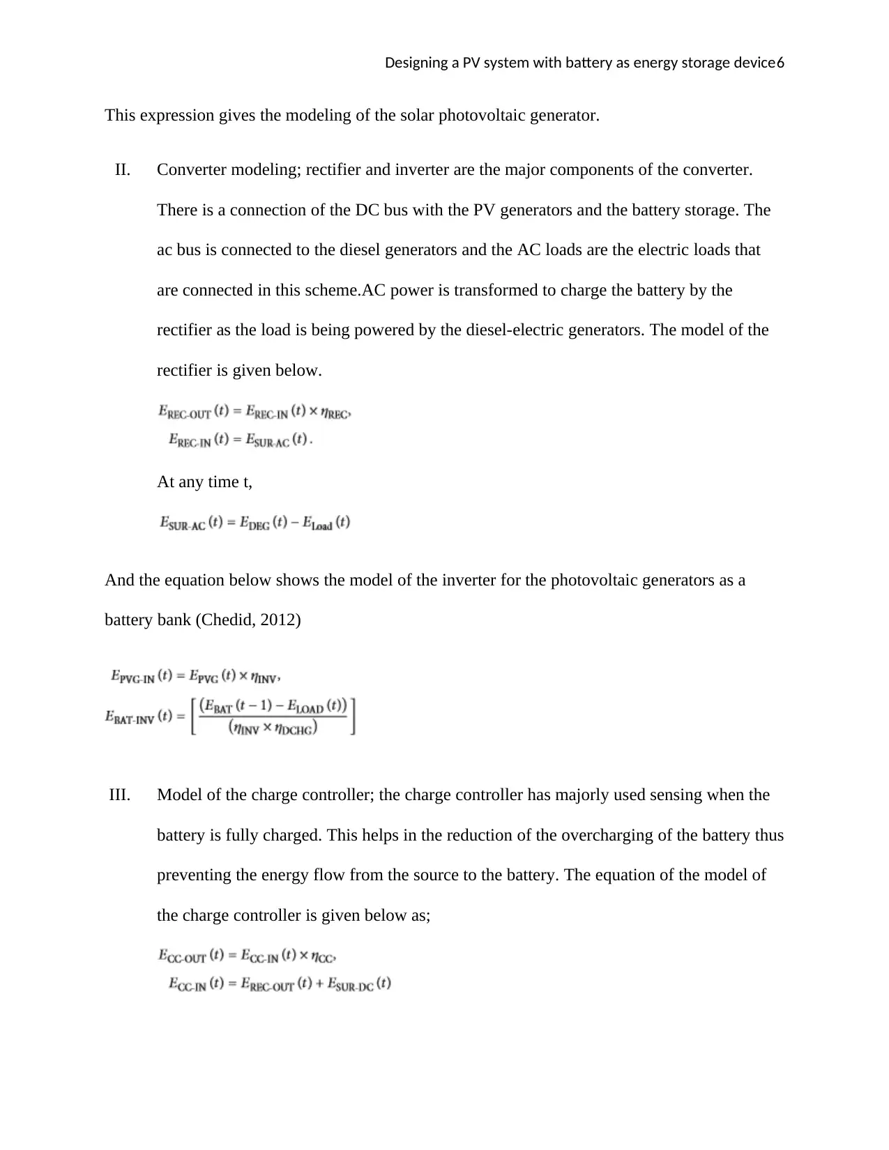
II. Converter modeling; rectifier and inverter are the major components of the converter.
There is a connection of the DC bus with the PV generators and the battery storage. The
ac bus is connected to the diesel generators and the AC loads are the electric loads that
are connected in this scheme.AC power is transformed to charge the battery by the
rectifier as the load is being powered by the diesel-electric generators. The model of the
rectifier is given below.
At any time t,
And the equation below shows the model of the inverter for the photovoltaic generators as a
battery bank (Chedid, 2012)
III. Model of the charge controller; the charge controller has majorly used sensing when the
battery is fully charged. This helps in the reduction of the overcharging of the battery thus
preventing the energy flow from the source to the battery. The equation of the model of
the charge controller is given below as;
This expression gives the modeling of the solar photovoltaic generator.
II. Converter modeling; rectifier and inverter are the major components of the converter.
There is a connection of the DC bus with the PV generators and the battery storage. The
ac bus is connected to the diesel generators and the AC loads are the electric loads that
are connected in this scheme.AC power is transformed to charge the battery by the
rectifier as the load is being powered by the diesel-electric generators. The model of the
rectifier is given below.
At any time t,
And the equation below shows the model of the inverter for the photovoltaic generators as a
battery bank (Chedid, 2012)
III. Model of the charge controller; the charge controller has majorly used sensing when the
battery is fully charged. This helps in the reduction of the overcharging of the battery thus
preventing the energy flow from the source to the battery. The equation of the model of
the charge controller is given below as;
⊘ This is a preview!⊘
Do you want full access?
Subscribe today to unlock all pages.
Trusted by 1+ million students worldwide
Designing a PV system with battery as energy storage device7
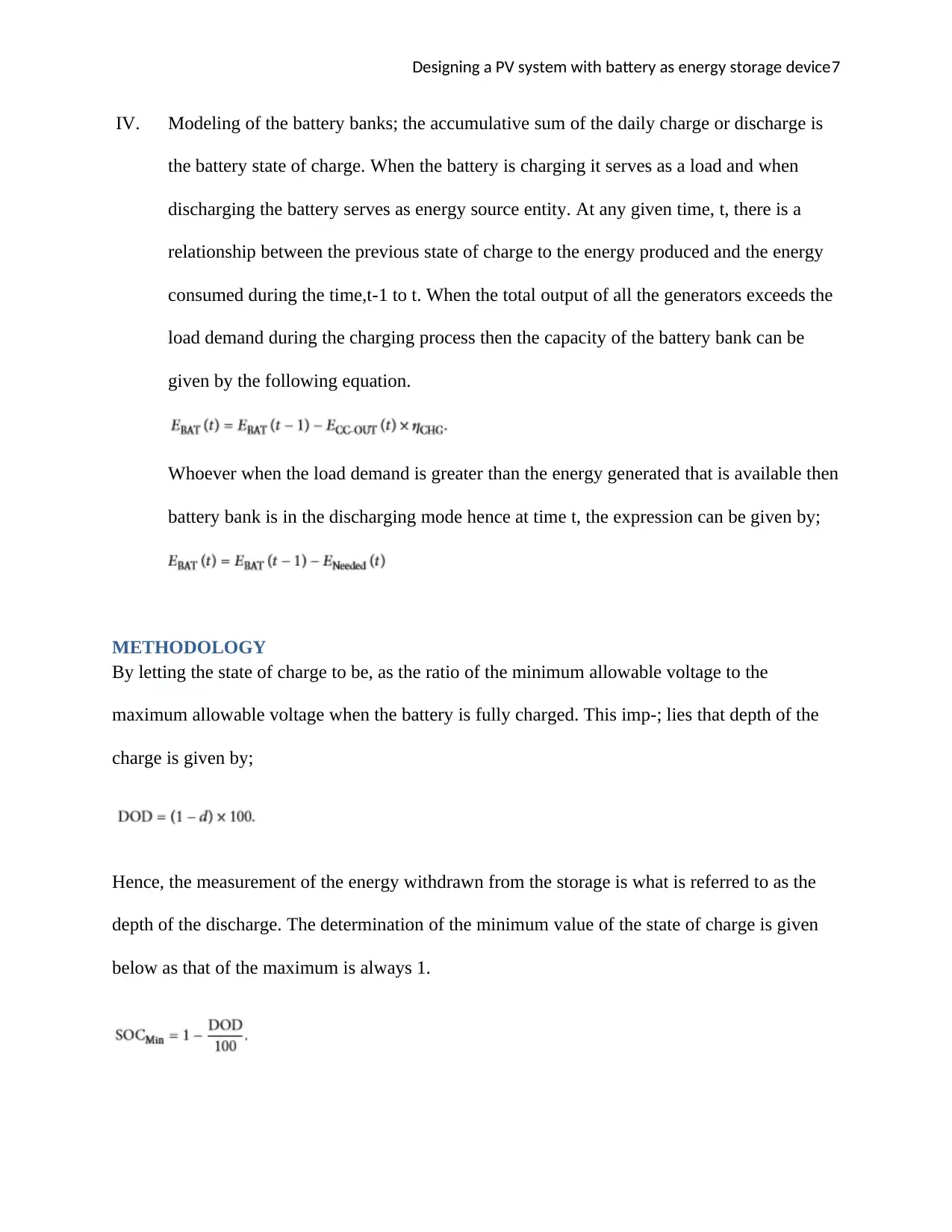
IV. Modeling of the battery banks; the accumulative sum of the daily charge or discharge is
the battery state of charge. When the battery is charging it serves as a load and when
discharging the battery serves as energy source entity. At any given time, t, there is a
relationship between the previous state of charge to the energy produced and the energy
consumed during the time,t-1 to t. When the total output of all the generators exceeds the
load demand during the charging process then the capacity of the battery bank can be
given by the following equation.
Whoever when the load demand is greater than the energy generated that is available then
battery bank is in the discharging mode hence at time t, the expression can be given by;
METHODOLOGY
By letting the state of charge to be, as the ratio of the minimum allowable voltage to the
maximum allowable voltage when the battery is fully charged. This imp-; lies that depth of the
charge is given by;
Hence, the measurement of the energy withdrawn from the storage is what is referred to as the
depth of the discharge. The determination of the minimum value of the state of charge is given
below as that of the maximum is always 1.
Paraphrase This Document
Need a fresh take? Get an instant paraphrase of this document with our AI Paraphraser
Designing a PV system with battery as energy storage device8
MATHEMATICAL COST OF THE MODEL
This paper has done the system development that gives the representation of the total sum of the
options that are considered towards the environment and on the economy.
COMPARISON OF THE COST OF THE CONNECTION OF THE GRID WITH THE
SOLAR SYSTEM
This kind of energy is sustainable, plenty and it is also renewable. Using the solar energy there is
lower monthly utility bill and financial returns. The installation of this kind of system is much
lower compared to other systems.
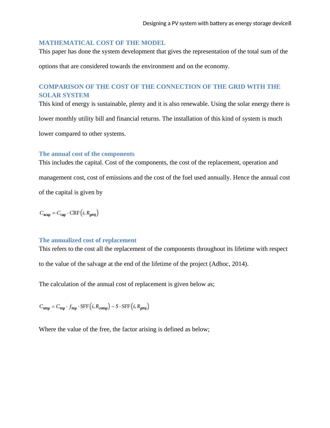
The annual cost of the components
This includes the capital. Cost of the components, the cost of the replacement, operation and
management cost, cost of emissions and the cost of the fuel used annually. Hence the annual cost
of the capital is given by
The annualized cost of replacement
This refers to the cost all the replacement of the components throughout its lifetime with respect
to the value of the salvage at the end of the lifetime of the project (Adhoc, 2014).
The calculation of the annual cost of replacement is given below as;
Where the value of the free, the factor arising is defined as below;
MATHEMATICAL COST OF THE MODEL
This paper has done the system development that gives the representation of the total sum of the
options that are considered towards the environment and on the economy.
COMPARISON OF THE COST OF THE CONNECTION OF THE GRID WITH THE
SOLAR SYSTEM
This kind of energy is sustainable, plenty and it is also renewable. Using the solar energy there is
lower monthly utility bill and financial returns. The installation of this kind of system is much
lower compared to other systems.
The annual cost of the components
This includes the capital. Cost of the components, the cost of the replacement, operation and
management cost, cost of emissions and the cost of the fuel used annually. Hence the annual cost
of the capital is given by
The annualized cost of replacement
This refers to the cost all the replacement of the components throughout its lifetime with respect
to the value of the salvage at the end of the lifetime of the project (Adhoc, 2014).
The calculation of the annual cost of replacement is given below as;
Where the value of the free, the factor arising is defined as below;
Designing a PV system with battery as energy storage device9
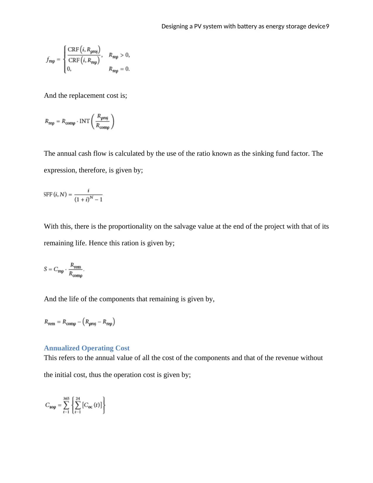
And the replacement cost is;
The annual cash flow is calculated by the use of the ratio known as the sinking fund factor. The
expression, therefore, is given by;
With this, there is the proportionality on the salvage value at the end of the project with that of its
remaining life. Hence this ration is given by;
And the life of the components that remaining is given by,
Annualized Operating Cost
This refers to the annual value of all the cost of the components and that of the revenue without
the initial cost, thus the operation cost is given by;
⊘ This is a preview!⊘
Do you want full access?
Subscribe today to unlock all pages.
Trusted by 1+ million students worldwide
Designing a PV system with battery as energy storage device10
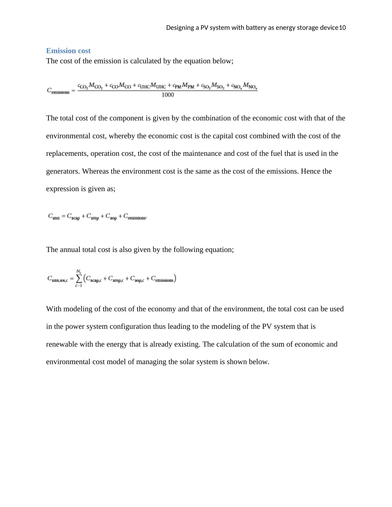
Emission cost
The cost of the emission is calculated by the equation below;
The total cost of the component is given by the combination of the economic cost with that of the
environmental cost, whereby the economic cost is the capital cost combined with the cost of the
replacements, operation cost, the cost of the maintenance and cost of the fuel that is used in the
generators. Whereas the environment cost is the same as the cost of the emissions. Hence the
expression is given as;
The annual total cost is also given by the following equation;
With modeling of the cost of the economy and that of the environment, the total cost can be used
in the power system configuration thus leading to the modeling of the PV system that is
renewable with the energy that is already existing. The calculation of the sum of economic and
environmental cost model of managing the solar system is shown below.
Paraphrase This Document
Need a fresh take? Get an instant paraphrase of this document with our AI Paraphraser
Designing a PV system with battery as energy storage device11
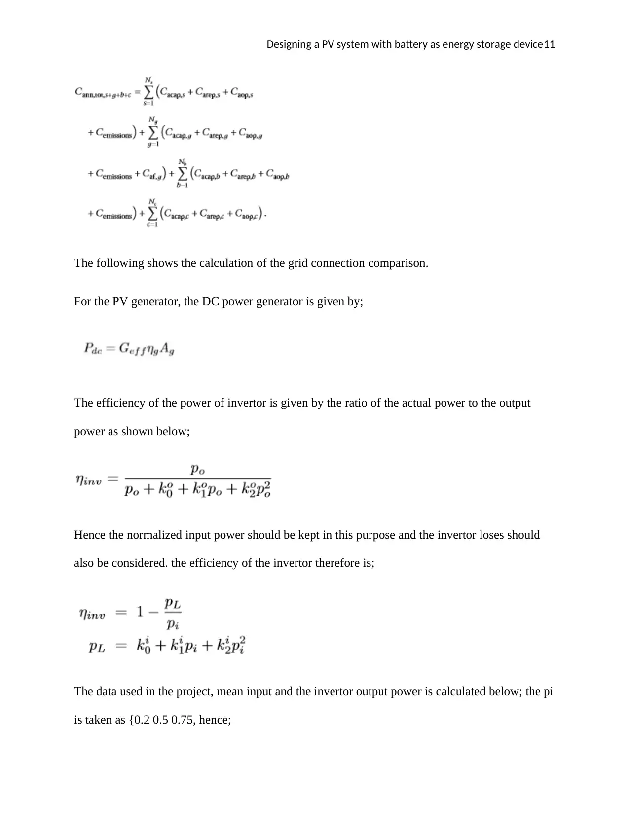
The following shows the calculation of the grid connection comparison.
For the PV generator, the DC power generator is given by;
The efficiency of the power of invertor is given by the ratio of the actual power to the output
power as shown below;
Hence the normalized input power should be kept in this purpose and the invertor loses should
also be considered. the efficiency of the invertor therefore is;
The data used in the project, mean input and the invertor output power is calculated below; the pi
is taken as {0.2 0.5 0.75, hence;
Designing a PV system with battery as energy storage device12
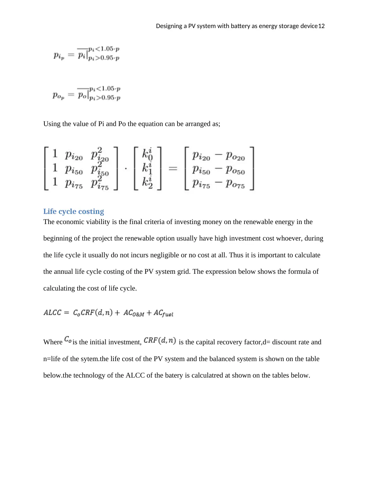
Using the value of Pi and Po the equation can be arranged as;
Life cycle costing
The economic viability is the final criteria of investing money on the renewable energy in the
beginning of the project the renewable option usually have high investment cost whoever, during
the life cycle it usually do not incurs negligible or no cost at all. Thus it is important to calculate
the annual life cycle costing of the PV system grid. The expression below shows the formula of
calculating the cost of life cycle.
Where is the initial investment, is the capital recovery factor,d= discount rate and
n=life of the sytem.the life cost of the PV system and the balanced system is shown on the table
below.the technology of the ALCC of the batery is calculatred at shown on the tables below.
⊘ This is a preview!⊘
Do you want full access?
Subscribe today to unlock all pages.
Trusted by 1+ million students worldwide
1 out of 27
Related Documents


Your All-in-One AI-Powered Toolkit for Academic Success.
+13062052269
info@desklib.com
Available 24*7 on WhatsApp / Email
![[object Object]](/_next/static/media/star-bottom.7253800d.svg)
Unlock your academic potential
Copyright © 2020–2026 A2Z Services. All Rights Reserved. Developed and managed by ZUCOL.