Project Proposal: CNT Desktop Reactor with Plasma Enriched Growth
VerifiedAdded on 2020/04/07
|8
|3470
|86
Project
AI Summary
This project proposal outlines the design and development of a carbon nanotube (CNT) desktop reactor with plasma-enriched growth capabilities. The project focuses on enhancing the growth of vertical carbon nanotubes using plasma-enhanced chemical vapor deposition (PECVD) techniques. The proposal details the benefits of adding plasma, including improved reactant gas decomposition, electric field generation for vertical alignment, and increased energy injection. It explores various design modules, including the reaction chamber, internal chamber assembly, and base supports, along with discussions on usability and analysis. The final design incorporates a six-way cross chamber with a remotely inductive plasma source to facilitate easier control of the electric field and improve system adjustability. The project also addresses the selection of materials, electrode assembly, and substrate holder design, with considerations for both local and remote plasma generation. The proposal concludes with a detailed description of the final design, including chamber geometry, internal chamber components, and base supports, along with an analysis of usability and initial setup procedures.
Carbon nanotube desktop reactor with plasma enriched growth 1
Project Proposal on
Carbon nanotube desktop reactor with plasma enriched growth
By Name
Course
Instructor
Institution
Location
Date
Project Proposal on
Carbon nanotube desktop reactor with plasma enriched growth
By Name
Course
Instructor
Institution
Location
Date
Paraphrase This Document
Need a fresh take? Get an instant paraphrase of this document with our AI Paraphraser
Carbon nanotube desktop reactor with plasma enriched growth 2
Abstract
Carbon nanotubes have various roles that involve their use in mechanical and electronic devices
in small nature. The carbon nanotubes that are isolated singularly exhibit inability to grow under
the conditions of chemical deposition. Researchers lately suggest that plasma addition to the
chemical depositions structures highly improve the chances developing vertical carbon
nanotubes. (Ebbesen, 2010).To attain this goal, we systematically identify customer needs as
well as engineering specifications. These are then analyzed through a quality deployment process
that ascertains the following key parameters:
Regulation of conditions of operation, which controls the pressure, plasma, temperature,
and rate of flow.
Electrode gap, that’s adjustable to show changes in the electric field surroundings and
size (Yang, 2009)
Introduction
Carbon nanotubes show enormous panorama in uses through many industries such as the
electronics and radical compounds. Growing isolated carbon nanotube is usually required most
of these uses. Chemical vapour deposition procedures are now a routine in growing of carbon
nanotubes. Chemical vapour deposition can support the growth of dense medium of elevated
carbon nanotubes though cannot generate vertical carbon nanotubes. The latest study suggests
that including plasma to carbon vapour deposition procedure can significantly enhance the
possibility of developing vertical Carbon nanotubes. (Bishop, 2013)
Benefits of adding plasma
It helps in decomposing reactant gases used in the production of nanotubes.
Generates an electric field that helps in the vertical alignment of the carbon nanotubes.
Injects additional energy. (Chopra, 2012)
Background research reveals four principal means of generating plasma for the plasma enhanced
chemical vapour deposition systems: direct current, inductively coupled, RF triode and
microwave. Plasma enhanced vapour deposition methods are mainly classified into three
modules, and another associate module design: plasma coil, reaction chamber, electronics,
controllers of operational condition, substrate holder and the heating assembly. Customer
necessities and provisions are used in providing a guideline for the formulation of the initial
concepts pertaining every module. (Huimin Liu, 2013)
The ultimate design fits into 0.457m by 0.457m base platter and height within 0.305m. Reaction
chamber comprises three orthogonal tubes mutually intersecting at the midpoint. A quartz tube is
fixed at the end of one its tubes. A plasma wind is done on the tube to aide ignition of the
reactant gases as they enter reaction chamber. Full substrate holder, adjustable electrode and the
heating process get packed in one tray that’s able to slide into or out of reaction chamber. The
infrared sensor and the chamber are designed into a stand containing a linear bearing that’s
suitable for the purpose opening and closing of the chamber. (Jiyang Fan, 2014)
The whole chamber comprises commercially available assembled components, with the
electrode, system tray, heat sink, and system stand and substrate system. (Franssila, 2010)
Design modules
Carbon nanotube desktop reactor with plasma enriched growth 3
Essentially, a reaction chamber is the flundamental element of all plasma enhanced chemical
vapour deposition systems hence much effort is accorded to it in terms of design. It’s this
chamber that houses the process of nanotube growth as well as plasma generation. It comprises
of viewports, chamber walls, in and out reactant gas passage and an electrical feed. The rest of
the modules depend on reaction chamber design. The internal chamber as a module hugely relies
on reaction chamber’s interior geometry. Therefore, concepts needed to be employed for reaction
chamber design first, before much effort was afforded the other modules. (Sharpe, 2009)A
pumping system, infrared sensor and fittings are selected to enhance the process of making
controllers of an operating condition. As for the supporting electronics and plasma coil, a
matching network, power supply and coil design are developed. An electrode assembly is
designed as an extra design work in the internal chamber assemblage.
Strategies for plasma enhanced chemical vapour deposition
Local plasma, plasma is created right over the substrate through growing environment.
Remote plasma, plasma is generated separately from the growing environment after
which it’s made to flow to the substrate. (Zhang, 2012)The main drawback of remote
plasma is that weaker electric field necessary for nanotubes vertical alignment for vertical
alignment of the nanotubes is easily overcome by any independent electric field
separately generated near the substrate. Thus majority design concepts employ remote
plasma. (Popov, 2008)
Concept Summary
Seven concepts as illustrated in the figures below were generated for this design with two of the
catering for every type of the geometry chamber. All the concepts utilized both the local and
plasma approaches. Materials used as stainless and quartz. Adjustable electrode stands out as a
key design module here. The box section containing plasma system has antennae have the shape
of a heating coil, located on the outer side of the chamber to aide ignition of the local plasma.
The front section is open to facilitate substrate access. Remote plasma disjoins the electric field
and power source. The section box containing inductive plasma helps create the remote plasma
that moves in the chamber. One is required to open gas outlet end thereby providing for substrate
access. The tube holding the remote plasma helps in adding that plasma to the chemical vapour
deposition system with the oven as a heat source.
Direct current substrate bias and remotely inducted plasma the above tube design employs the
use of use of one quartz tube through which plasma is created using a coil at one end. The
electrodes placed on opposite end allow for voltage supply. Pyrex cross design from commercial
Pyrex cross has two ends, one for sample loading and the other one for plasma generation. A
cross design (six-way) can also be generated in a number of ways. A steel chamber and spherical
Pyrex with local plasma are also designed with the hemispherical Pyrex that allows us to view
substrate through nanotube growth.
Adjustable Electrode Sub module
Comprises of the automatic adjustment which employs the use of a direct current motor the two
wheels responsible for moving the electrode up and down. The seal has to be made dynamic
enough to enhance electrode movement at a constant pressure difference within the chamber and
⊘ This is a preview!⊘
Do you want full access?
Subscribe today to unlock all pages.
Trusted by 1+ million students worldwide
Carbon nanotube desktop reactor with plasma enriched growth 4
atmosphere. There is also manual adjustment which uses a wound rod with the electrode attached
to it. Rotation of the rod ensures that the electrode moves up and down. (Vossen, 2017)
Discussions and Observations
Laboratory research by most lab users who have tried different chemical vapour deposition
setups helps us make a choice among the two leading concepts of design. The vast experience
among laboratory users enables them to interact with most useful features that are essential in
improving the system usability. Watching the lab user’s setup, grow the carbon nanotubes also
enables us to understand the handling of the samples. Professional interaction with lab
technicians doing plasma research helps greatly in making the decision on the remote and local
plasma. Furthermore, they provide information involving the advantages of both sources of
plasma as well as a valuable necessary consultation knowledge on a suitable method of
generating plasma.
Final Concept
Remotely inductive plasma source allows easy decoupling of the plasma as well as controlling
the electric field. It’s also essential in improving system adjustability. Besides, it is relatively
cheaper compared to microwave plasma and provides for a cleaner operation (Ostrikov, 2007)
Therefore, exploring the option of six-arms cross provides for an enormous adjustment to be
made in the coming times. (Vladimirov, 2005)Hence the choice of a cross design. With limited
project time frame, buying the chamber parts the components helps in ensuring that the parts
assembled are easily capable of holding the vacuum as well as save on time that could be used
machining them. (Ramesh, 2009)
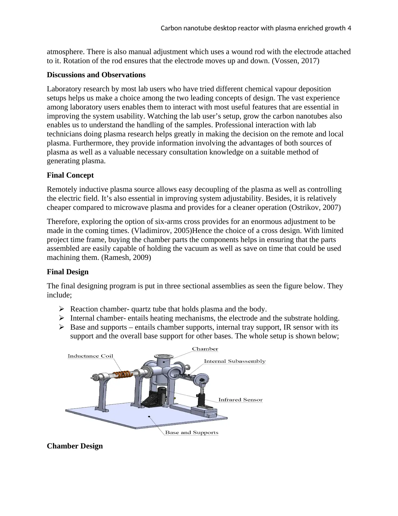
Final Design
The final designing program is put in three sectional assemblies as seen the figure below. They
include;
Reaction chamber- quartz tube that holds plasma and the body.
Internal chamber- entails heating mechanisms, the electrode and the substrate holding.
Base and supports – entails chamber supports, internal tray support, IR sensor with its
support and the overall base support for other bases. The whole setup is shown below;
Chamber Design
atmosphere. There is also manual adjustment which uses a wound rod with the electrode attached
to it. Rotation of the rod ensures that the electrode moves up and down. (Vossen, 2017)
Discussions and Observations
Laboratory research by most lab users who have tried different chemical vapour deposition
setups helps us make a choice among the two leading concepts of design. The vast experience
among laboratory users enables them to interact with most useful features that are essential in
improving the system usability. Watching the lab user’s setup, grow the carbon nanotubes also
enables us to understand the handling of the samples. Professional interaction with lab
technicians doing plasma research helps greatly in making the decision on the remote and local
plasma. Furthermore, they provide information involving the advantages of both sources of
plasma as well as a valuable necessary consultation knowledge on a suitable method of
generating plasma.
Final Concept
Remotely inductive plasma source allows easy decoupling of the plasma as well as controlling
the electric field. It’s also essential in improving system adjustability. Besides, it is relatively
cheaper compared to microwave plasma and provides for a cleaner operation (Ostrikov, 2007)
Therefore, exploring the option of six-arms cross provides for an enormous adjustment to be
made in the coming times. (Vladimirov, 2005)Hence the choice of a cross design. With limited
project time frame, buying the chamber parts the components helps in ensuring that the parts
assembled are easily capable of holding the vacuum as well as save on time that could be used
machining them. (Ramesh, 2009)
Final Design
The final designing program is put in three sectional assemblies as seen the figure below. They
include;
Reaction chamber- quartz tube that holds plasma and the body.
Internal chamber- entails heating mechanisms, the electrode and the substrate holding.
Base and supports – entails chamber supports, internal tray support, IR sensor with its
support and the overall base support for other bases. The whole setup is shown below;
Chamber Design
Paraphrase This Document
Need a fresh take? Get an instant paraphrase of this document with our AI Paraphraser
Carbon nanotube desktop reactor with plasma enriched growth 5
In making a design decision for the chamber, the cross geometry is purchased as it’s more
flexible and has a huge range of standard components available to select from in choosing this.
All of its projections attain Klein Flanges standards set by ISO thus allows profoundly easy fit all
together. The gas is streamed through a fitting outlined in the diagram below. It then travels the
quartz tube that is attached to two connect fittings to allow for easy exchange of fresh tubes as
well as the tubes with different lengths. This tube is then wound with a copper wire, then linked
to a plasma-producing generator. Another quick connection is then provided, to connect quartz
tube with the other left end in the six-way cross-chamber. The upper and back The upper and
back projection in this chamber has a number of cordial glass avenues that enable us to view the
internal features as the lower projection helps us achieve an optical access to the IR sensor. The
front projection allows for an electrical feeding passage consisting of individual eight sealed
pressure copper pins. Thereafter, the gas flows out through the standard KF projection that is
attached to the steel hose connected to the vacuum pump.
Internal Chamber Assembly
This chamber performs the task of giving mutual support to every element used in carbon
nanotube making process. The essential section of assembly encompasses a system tray, that is
connected to electrical feed through projection by use of a set of screw collars and steel pins
(dowel pins). These pins are then pressed to fit in the projection and slip to exactly fit into the
system tray. The lower three pins holding electric feed into the system can be removed to help
knock off any interference they may bring to the system tray. (Seshan, 2012)
There are two rods in the grooves laid tray system, whose main role is supporting the gathering
of the substrate and keeping it isolated electrically from the chamber and the system tray.
Substrate assemblage comprises a heating element that is resistive (silicon) and the heat sinks
(two). The heating element provides support to the substrate. The heat sinks hold the heating
element, as well as allowing current through it, enabling it to heat up the substrate in the long
run. The second figure below gives an outlook of how a heat sink is constructed (Mattox, 2016).
To create the electric field, an electrode is used. It is supported by the quartz rods vertically set in
the tray system. Silver tipped screw sets are then used to control the height. The electrode and
the heat sinks are connected to one of the feed pins each separately. The remaining two pins will
be used in the removable thermocouple for the purpose of IR sensor calibration. Lastly, the
connection between the actual clamps, wires, is determined. (Popov, 2008)
Base and Supports
The base plate is made of alluminium and also holds the chamber supports, which are mounted
to it. The supports help in keeping a fixed height of the chamber. It is also the base support into
which the IR sensor is screwed. The stand for IR sensor gives a provision for adjusting the sensor
vertically for the purpose of proper calibration to an appropriate height. The support for the
system tray keeps the internal structures with system tray at the desired height designed. This
holder, system tray, helps in proper adjustment of the stand aligning it with the chamber through
an efficient vertical motion it provides. This holder is designed to be able to slide on the rail thus
allowing movement of system tray completely from the chamber, as shown in the figure below.
Essentially, it’s useful in substrate loading and off-loading, in the growing of the carbon
nanotubes, enhancing cleaning of the whole system tray through its complete removal and
replacement of the heating elements.
Carbon nanotube desktop reactor with plasma enriched growth 6
Analysis regarding usability; INITIAL SET-UP
I. Support the projection with the substrate frame on the slot of the chamber and then fix the
gas to the tube inlet thereafter fix the pump to the chamber outlet.
II. Slide the projection with substrate into the chamber and link every electrical feed from
the projection supporting substrate to the electrodes.
III. Put the substrate into a holder and then slide it gently and finish all the electrical links
through the projections by linking the direct current power supply with the feed through.
IV. Link the coil with marching network, marching network and power source then the
controller of the automatic network marching.
V. Ensure all viewports and projections are in right positions. (Seshan, 2012)
PROCESS SET-UP
I. Induce a low pressure in the chamber by introducing inert gas like helium and open the
gas flow while ensuring a desired rate of flow.
II. Now put on the power source maintaining a desirable power level using an option of
forwarding power in the generator, then wait until the generation of plasma in quartz tube
is done, ensuring that the impedance source of 50 Ohms equals’ plasma impedance.
III. After carbon nanotube reaches the desirable levels, put off the power source, vacuum and
flow rates.
IV. Give it some minutes before embarking on dismounting of substrate stand and the flange
in order to gain substrate access.
V. Detach all the electrical connections carefully then take out the substrate. In case a direct
current source is used instead, for power generation, then the electrode would have to be
removed before getting an access to the substrate. (Popov, 2008)
Validation Plan
In ensuring that the project meets engineering specifications, a number of required experiments
have to be conducted (Etching, 2008). All of the mandatory tests to be performed are provided in
the figure below, in an order of low priority in their undertaking. To avoid help avoid failure in
some parts, wall temperatures and pressure of the chamber are checked and controlled. A
calibrated IR sensor is used in measuring temperature, whose analysis helps determine if the
required conditions are achieved, and the pressure measured by a pressure gauge.
Plasma creation is visually seen through its ignition in the clear quartz tube. A confirmation of
the growth of carbon nanotubes is achieved through the viewing of certain black growth
occurring on the wafer or scanning by electronic microscope. Finally, SEM will go on to prove
that this system has the capacity to produce isolated nanotubes vertically. (Franssila, 2010)
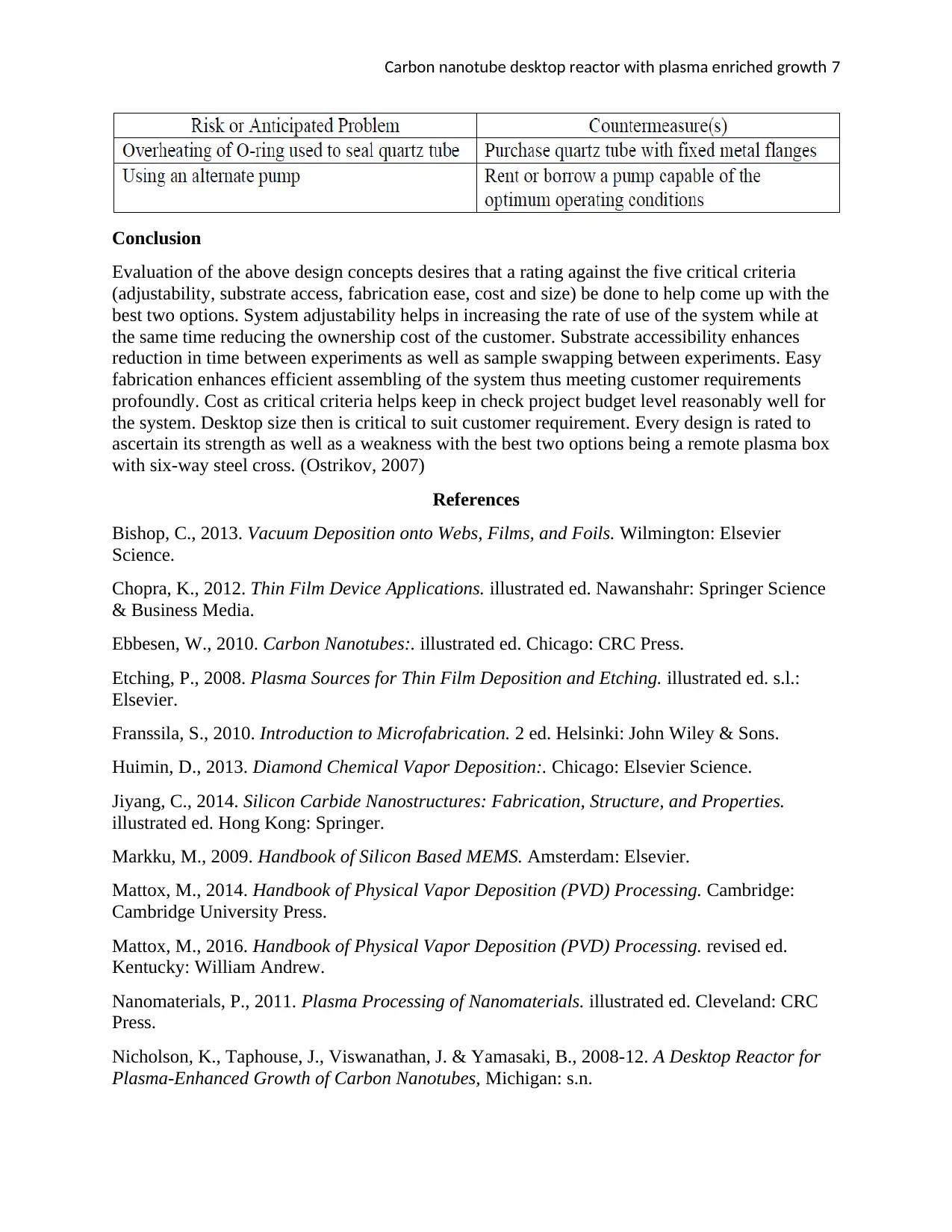
Risks and Countermeasures
During the process of the undertaking of the project work, there is a certain foreseeable risk level
that basically needs to be factored in the process of project work plan. It's therefore essential that
we formulate the necessary measures to counteract these risks involved in the implementation
process. Proper handling of such issues greatly helps in making the project within the stipulated
timelines. The table below gives a summary of anticipated risks, problems as well as associated
countermeasures (Vossen, 2017)
Analysis regarding usability; INITIAL SET-UP
I. Support the projection with the substrate frame on the slot of the chamber and then fix the
gas to the tube inlet thereafter fix the pump to the chamber outlet.
II. Slide the projection with substrate into the chamber and link every electrical feed from
the projection supporting substrate to the electrodes.
III. Put the substrate into a holder and then slide it gently and finish all the electrical links
through the projections by linking the direct current power supply with the feed through.
IV. Link the coil with marching network, marching network and power source then the
controller of the automatic network marching.
V. Ensure all viewports and projections are in right positions. (Seshan, 2012)
PROCESS SET-UP
I. Induce a low pressure in the chamber by introducing inert gas like helium and open the
gas flow while ensuring a desired rate of flow.
II. Now put on the power source maintaining a desirable power level using an option of
forwarding power in the generator, then wait until the generation of plasma in quartz tube
is done, ensuring that the impedance source of 50 Ohms equals’ plasma impedance.
III. After carbon nanotube reaches the desirable levels, put off the power source, vacuum and
flow rates.
IV. Give it some minutes before embarking on dismounting of substrate stand and the flange
in order to gain substrate access.
V. Detach all the electrical connections carefully then take out the substrate. In case a direct
current source is used instead, for power generation, then the electrode would have to be
removed before getting an access to the substrate. (Popov, 2008)
Validation Plan
In ensuring that the project meets engineering specifications, a number of required experiments
have to be conducted (Etching, 2008). All of the mandatory tests to be performed are provided in
the figure below, in an order of low priority in their undertaking. To avoid help avoid failure in
some parts, wall temperatures and pressure of the chamber are checked and controlled. A
calibrated IR sensor is used in measuring temperature, whose analysis helps determine if the
required conditions are achieved, and the pressure measured by a pressure gauge.
Plasma creation is visually seen through its ignition in the clear quartz tube. A confirmation of
the growth of carbon nanotubes is achieved through the viewing of certain black growth
occurring on the wafer or scanning by electronic microscope. Finally, SEM will go on to prove
that this system has the capacity to produce isolated nanotubes vertically. (Franssila, 2010)
Risks and Countermeasures
During the process of the undertaking of the project work, there is a certain foreseeable risk level
that basically needs to be factored in the process of project work plan. It's therefore essential that
we formulate the necessary measures to counteract these risks involved in the implementation
process. Proper handling of such issues greatly helps in making the project within the stipulated
timelines. The table below gives a summary of anticipated risks, problems as well as associated
countermeasures (Vossen, 2017)
⊘ This is a preview!⊘
Do you want full access?
Subscribe today to unlock all pages.
Trusted by 1+ million students worldwide
Carbon nanotube desktop reactor with plasma enriched growth 7
Conclusion
Evaluation of the above design concepts desires that a rating against the five critical criteria
(adjustability, substrate access, fabrication ease, cost and size) be done to help come up with the
best two options. System adjustability helps in increasing the rate of use of the system while at
the same time reducing the ownership cost of the customer. Substrate accessibility enhances
reduction in time between experiments as well as sample swapping between experiments. Easy
fabrication enhances efficient assembling of the system thus meeting customer requirements
profoundly. Cost as critical criteria helps keep in check project budget level reasonably well for
the system. Desktop size then is critical to suit customer requirement. Every design is rated to
ascertain its strength as well as a weakness with the best two options being a remote plasma box
with six-way steel cross. (Ostrikov, 2007)
References
Bishop, C., 2013. Vacuum Deposition onto Webs, Films, and Foils. Wilmington: Elsevier
Science.
Chopra, K., 2012. Thin Film Device Applications. illustrated ed. Nawanshahr: Springer Science
& Business Media.
Ebbesen, W., 2010. Carbon Nanotubes:. illustrated ed. Chicago: CRC Press.
Etching, P., 2008. Plasma Sources for Thin Film Deposition and Etching. illustrated ed. s.l.:
Elsevier.
Franssila, S., 2010. Introduction to Microfabrication. 2 ed. Helsinki: John Wiley & Sons.
Huimin, D., 2013. Diamond Chemical Vapor Deposition:. Chicago: Elsevier Science.
Jiyang, C., 2014. Silicon Carbide Nanostructures: Fabrication, Structure, and Properties.
illustrated ed. Hong Kong: Springer.
Markku, M., 2009. Handbook of Silicon Based MEMS. Amsterdam: Elsevier.
Mattox, M., 2014. Handbook of Physical Vapor Deposition (PVD) Processing. Cambridge:
Cambridge University Press.
Mattox, M., 2016. Handbook of Physical Vapor Deposition (PVD) Processing. revised ed.
Kentucky: William Andrew.
Nanomaterials, P., 2011. Plasma Processing of Nanomaterials. illustrated ed. Cleveland: CRC
Press.
Nicholson, K., Taphouse, J., Viswanathan, J. & Yamasaki, B., 2008-12. A Desktop Reactor for
Plasma-Enhanced Growth of Carbon Nanotubes, Michigan: s.n.
Paraphrase This Document
Need a fresh take? Get an instant paraphrase of this document with our AI Paraphraser
Carbon nanotube desktop reactor with plasma enriched growth 8
Ostrikov, K., 2007. Plasma-Aided Nanofabrication:. Sydney: John Wiley & Sons.
Ostrikov, K., 2008. PLASMA NANOSCIENCE. SYDNEY: JOHN WILEY AND SONS.
Pierson, H. O., 2012. Handbook of Chemical Vapor Deposition:. Paris: Elsevier Science.
Popov, O. A., 2008. High-Density Plasma Sources: Design, Physics, and Performance.
illustrated ed. Mosco: Noyes Publications.
Popov, O. A., 2013. High-Density Plasma Sources: Design, Physics and Performance. Mosco:
Elsevier Science.
Ramesh, K., 2009. Nanomaterials: Mechanics and Mechanisms. illustrated, reprinted. Baltimore:
Springer Science & Business Media.
Seshan, K., 2012. Handbook of Thin Film Deposition: Techniques, Processes, and Technologies.
illustrated, revised ed. Arizona: William Andrew.
Sharpe, W., 2009. Springer Handbook of Experimental Solid Mechanics. illustrated ed.
Hampton: Springer Science & Business Media.
Vladimirov, S., 2005. Physics and Applications of Complex Plasmas. s.l. World Scientific.
Vossen, L., 2017. Physics of Thin Films:. revised ed. New York: Elsevier Science.
Yang, F., 2009. Micro and Nano Mechanical Testing:. illustrated ed. Berlin: Springer Science &
Business Media.
Zhang, Q., 2012. Advances in Nanodevices and Nanofabrication:. illustrated ed. London: CRC
Press.
1 out of 8

Your All-in-One AI-Powered Toolkit for Academic Success.
+13062052269
info@desklib.com
Available 24*7 on WhatsApp / Email
![[object Object]](/_next/static/media/star-bottom.7253800d.svg)
Unlock your academic potential
Copyright © 2020–2026 A2Z Services. All Rights Reserved. Developed and managed by ZUCOL.