Assessment of RC Bridge Beam Deck Deterioration in Malaysia
VerifiedAdded on 2022/11/23
|74
|16003
|1
Report
AI Summary
This report provides a detailed analysis of the deterioration of reinforced concrete (RC) bridge beam decks in Malaysia. It begins with an introduction to the problem of bridge deterioration, outlining research questions, objectives, and the scope of the study. A comprehensive literature review explores concrete microstructure, deterioration mechanisms such as carbonation and corrosion, and non-destructive testing methods used for bridge evaluation. The methodology includes a case study approach, focusing on three bridges in Malaysia, including visual inspections, material sampling, and pH testing. The results section presents data from non-destructive tests (NDT), environmental testing, and concrete microstructure analysis, including XRD and SEM/EDX testing. The discussion section interprets these results, offering insights into the causes of deterioration. The report concludes with recommendations for addressing the identified issues and suggests future research directions to improve bridge maintenance and extend the lifespan of these critical infrastructures. The report includes the use of the Public Works Department (JKR) and the importance of understanding different factors associated with the assessment of the bridge network. The report also discusses various problems associated with RC bridges and the importance of conducting inspections and evaluations to ensure safety and structural integrity. All these analysis are available on Desklib.
Deterioration of RC Bridge Beam Deck: What Went Wrong in Malaysia
Student Name
Subject Name
Date
Student Name
Subject Name
Date
Paraphrase This Document
Need a fresh take? Get an instant paraphrase of this document with our AI Paraphraser
Table of Contents
Executive Summary....................................................................................................................................4
Chapter 1: Introduction...............................................................................................................................5
Research Questions.................................................................................................................................6
Problem Statement..................................................................................................................................6
Objectives of Study.................................................................................................................................7
Main Objective...................................................................................................................................7
Specific Objectives.............................................................................................................................7
Scope......................................................................................................................................................8
Chapter 2: Literature Review......................................................................................................................8
Concrete Microstructure Analysis...........................................................................................................8
Cement paste.......................................................................................................................................8
Pore Structure...................................................................................................................................11
Interfacial Transition Zone................................................................................................................12
Microstructure of High Performance Concrete.................................................................................16
Effect of Microstructure on Strength as well as the Durability.........................................................18
Carbonation......................................................................................................................................21
Principle of Deterioration.....................................................................................................................22
External Attack.................................................................................................................................22
Internal Attack..................................................................................................................................23
Bridge Evaluation Using Nondestructive Testing.................................................................................24
Rebound Hammer Test.........................................................................................................................26
Problems in Concrete Members............................................................................................................29
Load Induced Crack..............................................................................................................................30
Corrosion Induced................................................................................................................................33
Chapter 3: Material and Methods..............................................................................................................35
Rebound Hammer Procedure................................................................................................................35
Procedure for Schmidt Rebound Hammer Test.................................................................................35
Chapter 4: Case Study...............................................................................................................................37
Site Location.........................................................................................................................................37
Visual Inspection..................................................................................................................................38
Detailed Design of Bridge....................................................................................................................39
Sampling and pH Testing......................................................................................................................40
Defect Mapping of all three Bridges.....................................................................................................41
Assessment...........................................................................................................................................43
Chapter 5: Results and Discussion............................................................................................................44
Non-Destructive Test (NDT) on Rebound Hammer.............................................................................44
Data for Temperature and Relative Humidity.......................................................................................46
Quantitative Results for Test (3322).....................................................................................................48
Sound Test............................................................................................................................................49
Elements and Standard Concentration..................................................................................................50
Concrete Structure Analysis..................................................................................................................54
Concrete Microstructure.......................................................................................................................56
XRD Testing.........................................................................................................................................59
Environmental Testing-Soil SEM/EDX Testing (Soil)-Sg. Cheh.........................................................60
Soil Microstructure...........................................................................................................................61
Soil CHN-S Test...............................................................................................................................64
Soil pH Test......................................................................................................................................64
Carbonation Test...............................................................................................................................65
Chapter 6: Conclusion and Recommendation...........................................................................................67
References................................................................................................................................................68
⊘ This is a preview!⊘
Do you want full access?
Subscribe today to unlock all pages.
Trusted by 1+ million students worldwide
Executive Summary
There are various complexes imbued as well as uncertainty which are largely associated with the
condition assessment of the makeable reinforced concrete bridges in Malaysia. This complexity
mainly considered to have developed from a number of problems. In essence, there are a number
of factors which are considered to have in-depth impacts on the conditions of the parametric
bridges. Thus, the condition assessment of the bridge network requires vast knowledge and
understanding of the different factors. These factors must be appraised in line with the structural
behaviors of the various concrete structures. Some of the structures often subjected to makeable
phenomena such as environmental effects, excessive loading as well as chemical attacks. The
evaluation can therefore be attained via the application of the comprehensive and knowledge-
based system. In the recent analysis, there is the using of the Public Works Department also
abbreviated as (JKR). The nature of the assessment associated with the Public Works
Department or (JKR) largely termed as the visual inspection. However, current comprehensive
system often requires the inclusion of both the visual inspection and the using of the non-
destructive tests. In addition to this, one can also use the distress investigation to examine the
structural failures in line with the bridges as well. This paper therefore discusses three case
studies of bridges in the Malaysia. The bridges discussed in this paper include Jalan Bendang
Siam, Senduk Hulu and Cheng. Further to this, there is also the documentation of the findings as
well as the drawing of the conclusions and recommendations from the study.
Paraphrase This Document
Need a fresh take? Get an instant paraphrase of this document with our AI Paraphraser
Chapter 1: Introduction
In Malaysia, the Public Works Department is regarded as the legal entity and custodian of the
more than 7000 bridges existing in the federal state. In addition to this, it is estimated that
number of bridges which are made up of the concrete sum up-to 70% of the overall bridges
existing in the country. Further to this, it is important to deduce that at least 250 bridges existing
in the country were built at the makeable beginning of the 1960s. Also, there are about 1000
bridges which were built between 1978 and 1979 and this alone has attained the estimate age of
40 years old. Preferably, 40 years is estimated and deduce as the mid-life span and age for any
typical bridge. Thus, at this level it is important to conduct the overall inspections and evaluation
with the aim of conduction rehabilitations required for the aspect. On the other hand, 75 years is
the overall useful and typical life span of the bridge. Therefore, most of the bridges in Malaysia
have attained the midlife span with some even exceeding the set limit and thus, it will be
important to conduct the deterioration and corrosion analysis of the bridges to attain the
suitability of the bridges. The assessment also aims at establishing the safety levels of these
bridges as well as the recommendations which one should consider as far as the failures in the
bridges is concerned [1].
There are various problems which are associated with the RC bridge in different countries. For
instance, the bridge failures in Malaysia primarily anticipated with the various terms such as the
distress, deteriorations, damages as well as bridge failures. The failures associated with the RC
bridges are often increasing in different countries. The past studies have reported that different
failures have been depicted in various states and countries and this cannot be overruled at all
costs. In the recent days, it is evidential that the activities in line with the evaluation and the
inspection of the bridges are quite complex and difficult to carry out as opposed to the
construction and the designing of new bridges. This process not only requires keenness but also
in-depth understanding for one to be able to notice the faults while at the same time making
sound engineering judgments. The judgment in lien with the visual inspection is not only
important for the maintenance but also for ensuring that the structure is safe over its lifetime. On
the other hand, all the calculations involve should be conducted while giving the allowances to
both the corroded sections as well as the existing faults in the bridges. Notably, it is important to
recommend that most of the old bridges were largely designed and built using the earlier codes
of practice and loadings. Fortunately, there was the incorporation of the high safety factors and
these codes in the designing of such bridges. Logically, it is important to incorporate the design
codes and safety factors when dealing the modern loading but this will require the reassessing of
the suitability and strength of the existing as well as future traffic [2].
Research Questions
Also, it is important to note that the inspection of the bridges tends to answer the following
research questions
What is the overall condition of the bridge is it sound or not?
Does the bridge behavior comply with the intensions of the designer in line with the
structural conformance?
What is the maximum load which these bridges can accommodate in line with the
safety value without causing or leading to any weakening?
What is the level of the corrosion and deterioration which one can report from the
assessment?
What is the strengthening program which one needs to allow the overall bridges to
carry in line with the present as well as future related traffic loadings?
Is the value established in line with the level of the corrosion and deterioration of the
bridges economical or requites maintenance?
Problem Statement
Considerably, it is essential to anticipate that bridges as well as other structures tend to
deteriorate and this is grounded on the use and time. Often than not, there are different factors
which contributes to the deterioration of the bridges and they include traffic, rain, thaw cycles,
climate, pollution, freeze, moisture variation and temperature. This deterioration problem can
lead to various impacts on the bridge such as causing failures of the bridge. Thus, it is important
to conduct periodic bridge assessment and inspection to curb this problem. The assessment of
⊘ This is a preview!⊘
Do you want full access?
Subscribe today to unlock all pages.
Trusted by 1+ million students worldwide
the bridge should focus on the implications, extension as well as the current deterioration state
and process. Other importance of conducting the inspection process is that it will help in
preventing the failures while at the same time assisting in giving the information which are often
necessary in coming up with the effective bridge network administration. During the inspection
process, it will necessary and fundamentally important to ascertain the various elements which
require urgent repairs, replacement and maintenance action. Also, these analogies can be
reported as far as the evaluation is concerned[3]. Thus, grounded on the established report the
administrative bodies will be in the position to explore and apply the gathered information in
establishing the programs as well as defining the priorities. There are two key aspects which one
can use when gathering the information as well as when exploring the bridges. These include
structural analysis as well as visual inspection. However, there is increase application of the
visual inspection in the present days. However, when the visual method is applied to conduct the
evaluation of the bridges, then it will be important to have a subjective rating. The subjective
rating should be assigned to the makeable bridge components by the decisive and responsible
inspector. In addition to this, the condition rating used in the process largely regarded as the
defined primary sets as well as qualitative analogy in line with the visual indicators. This is
largely used in the routine checking [4].
Objectives of Study
The objectives for this project often divided into two key subsections which include main
objective and specific objectives as discussed below
Main Objective
To assess the deterioration of RC Bridge Beam Deck: What Went Wrong in Malaysia
Specific Objectives
To explore three case study in line with the Deterioration of RC Bridge Beam Deck: What
Went Wrong in Malaysia
To explore the various tests and methods which are used to establish the Deterioration of RC
Bridge Beam Deck: What Went Wrong in Malaysia
To assess the recommendations for the problems
Paraphrase This Document
Need a fresh take? Get an instant paraphrase of this document with our AI Paraphraser
Scope
The research encompasses on the study of the three bridges which include Jambatan Sungai
Gantang, Hulu as well as Cheg. The bridges largely examined in lien with the RC deteriorations
in the Malaysia state. Thereafter, various recommendations and conclusion were drawn from the
three case studies.
Chapter 2: Literature Review
Concrete Microstructure Analysis
Concrete microstructure has three major components; they include inter-facial change region
between a cement paste as well as the aggregates, Pore structure as well as the cement paste. It is
important to note that the concrete microstructure is a heterogeneous in nature. Therefore, the
three components must be upgraded in order to achieve a strong durability as far as the concrete
is concerned as well as the improved strength mechanically[5].
Cement paste
The cement is mainly made up of alumina and silica largely abbreviated as (Al203) and (Si02)
respectively, iron oxide as well as the lime mostly abbreviated as (Fe2O3) and (CaO). The
ordinary Portland cement is made up of components such as the di-calcium silicate, tetra-
calcium alumi-noferrite, tri-calcium silicate as well as the tri-calcium aluminate. They mostly
abbreviated as (C2S), (C4AF), (C3S), (C3A) respectively. The hydrated cement paste
microstructure is made up of different phases, and they include calcium hydroxide, cement
particles, ettringite, calcium silicate, air voids as well as the unhydrated. The concrete is mixture
of the ordinary portal and cement as well as the water and the aggregate. To achieve desirable
end products as far as the concrete is concerned majorly during the practical , it is advisable to
add the additives together with different size particles as well as the specific surface zones into
the raw materials. The following diagram shows the materials specifically the raw ones of
concrete as well as the supplementary condiments in relation to the particle size as well as the
specific surface zones.
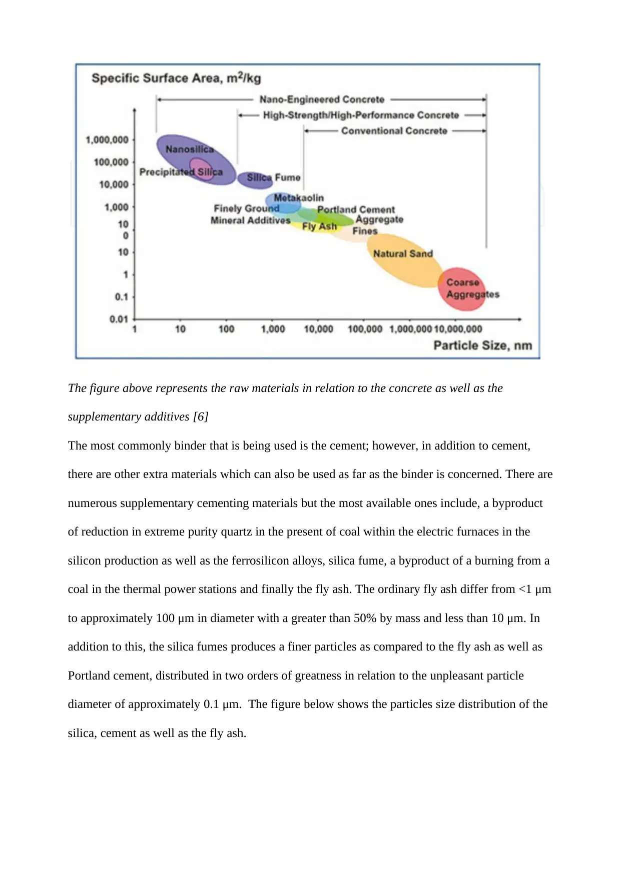
The figure above represents the raw materials in relation to the concrete as well as the
supplementary additives [6]
The most commonly binder that is being used is the cement; however, in addition to cement,
there are other extra materials which can also be used as far as the binder is concerned. There are
numerous supplementary cementing materials but the most available ones include, a byproduct
of reduction in extreme purity quartz in the present of coal within the electric furnaces in the
silicon production as well as the ferrosilicon alloys, silica fume, a byproduct of a burning from a
coal in the thermal power stations and finally the fly ash. The ordinary fly ash differ from <1 μm
to approximately 100 μm in diameter with a greater than 50% by mass and less than 10 μm. In
addition to this, the silica fumes produces a finer particles as compared to the fly ash as well as
Portland cement, distributed in two orders of greatness in relation to the unpleasant particle
diameter of approximately 0.1 μm. The figure below shows the particles size distribution of the
silica, cement as well as the fly ash.
⊘ This is a preview!⊘
Do you want full access?
Subscribe today to unlock all pages.
Trusted by 1+ million students worldwide
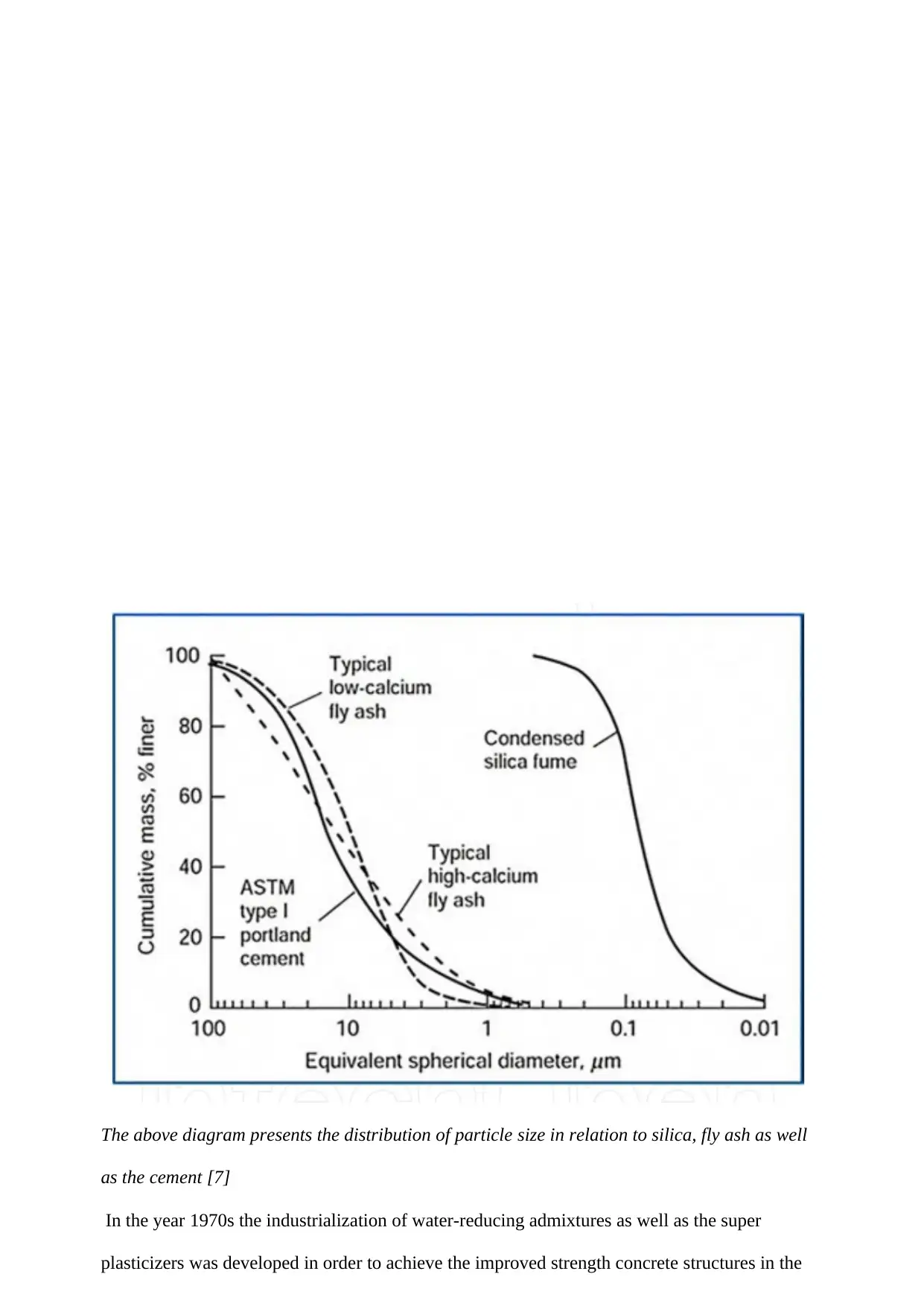
The above diagram presents the distribution of particle size in relation to silica, fly ash as well
as the cement [7]
In the year 1970s the industrialization of water-reducing admixtures as well as the super
plasticizers was developed in order to achieve the improved strength concrete structures in the
as the cement [7]
In the year 1970s the industrialization of water-reducing admixtures as well as the super
plasticizers was developed in order to achieve the improved strength concrete structures in the
Paraphrase This Document
Need a fresh take? Get an instant paraphrase of this document with our AI Paraphraser
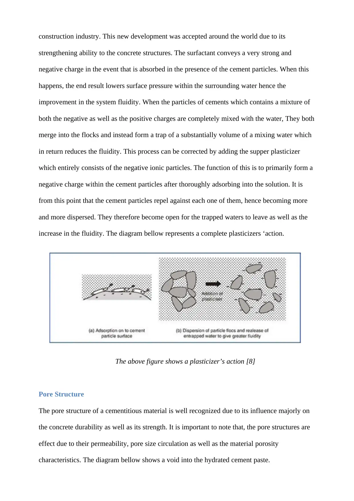
construction industry. This new development was accepted around the world due to its
strengthening ability to the concrete structures. The surfactant conveys a very strong and
negative charge in the event that is absorbed in the presence of the cement particles. When this
happens, the end result lowers surface pressure within the surrounding water hence the
improvement in the system fluidity. When the particles of cements which contains a mixture of
both the negative as well as the positive charges are completely mixed with the water, They both
merge into the flocks and instead form a trap of a substantially volume of a mixing water which
in return reduces the fluidity. This process can be corrected by adding the supper plasticizer
which entirely consists of the negative ionic particles. The function of this is to primarily form a
negative charge within the cement particles after thoroughly adsorbing into the solution. It is
from this point that the cement particles repel against each one of them, hence becoming more
and more dispersed. They therefore become open for the trapped waters to leave as well as the
increase in the fluidity. The diagram bellow represents a complete plasticizers ‘action.
The above figure shows a plasticizer’s action [8]
Pore Structure
The pore structure of a cementitious material is well recognized due to its influence majorly on
the concrete durability as well as its strength. It is important to note that, the pore structures are
effect due to their permeability, pore size circulation as well as the material porosity
characteristics. The diagram bellow shows a void into the hydrated cement paste.
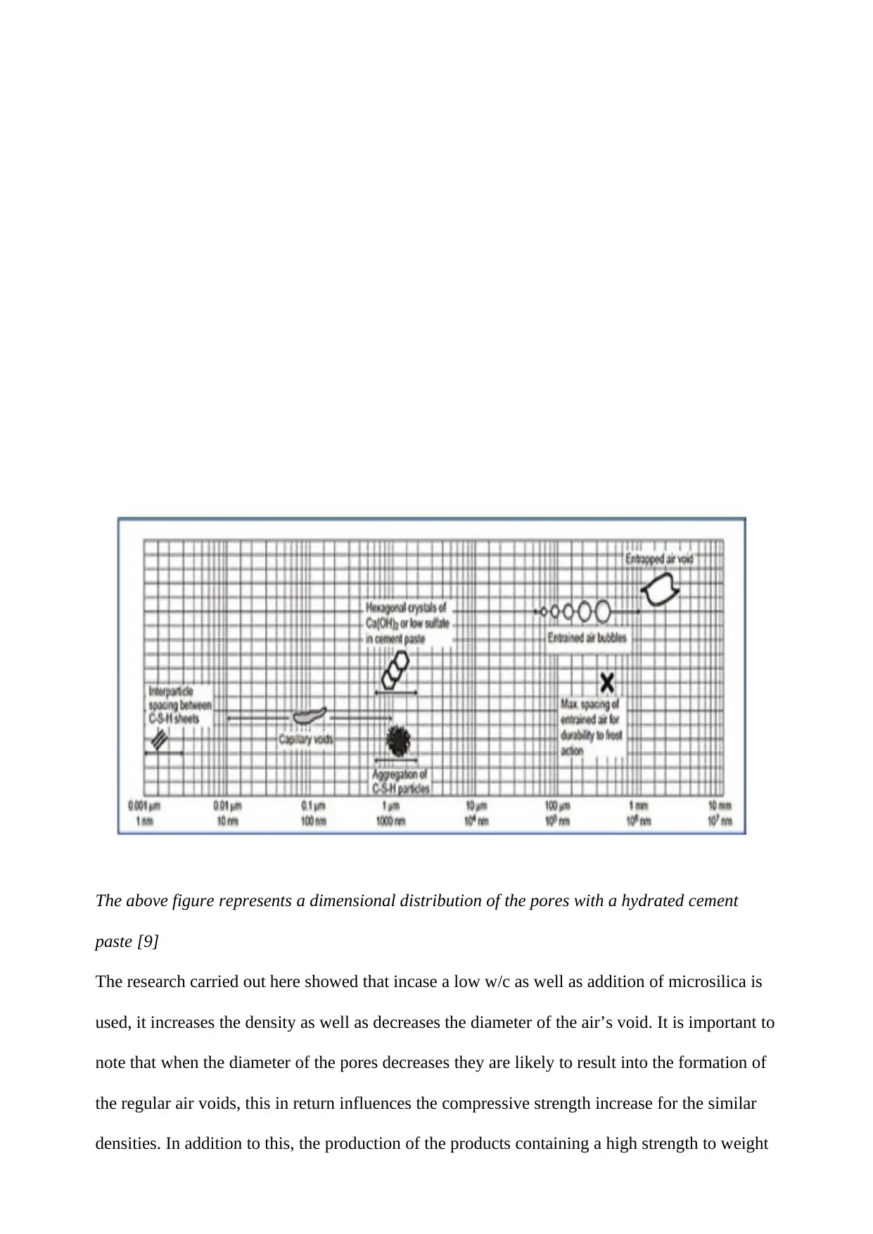
The above figure represents a dimensional distribution of the pores with a hydrated cement
paste [9]
The research carried out here showed that incase a low w/c as well as addition of microsilica is
used, it increases the density as well as decreases the diameter of the air’s void. It is important to
note that when the diameter of the pores decreases they are likely to result into the formation of
the regular air voids, this in return influences the compressive strength increase for the similar
densities. In addition to this, the production of the products containing a high strength to weight
⊘ This is a preview!⊘
Do you want full access?
Subscribe today to unlock all pages.
Trusted by 1+ million students worldwide
1 out of 74
Your All-in-One AI-Powered Toolkit for Academic Success.
+13062052269
info@desklib.com
Available 24*7 on WhatsApp / Email
![[object Object]](/_next/static/media/star-bottom.7253800d.svg)
Unlock your academic potential
Copyright © 2020–2026 A2Z Services. All Rights Reserved. Developed and managed by ZUCOL.