Short Circuit Calculations in Networks with Large DG Penetration
VerifiedAdded on 2020/05/08
|75
|13475
|38
Report
AI Summary
This report delves into the complexities of short circuit calculations within electrical networks that have a significant presence of distributed generation (DG), specifically focusing on wind energy. It begins with an introduction to the topic, followed by a thorough literature review covering various aspects such as wind turbine modeling, variable speed wind turbines (including DFIG), and the impact of DG on fault analysis. The methodology section outlines the grid component model and the modeling of different wind turbine types. The report uses DigSilent software for simulations. The expected outcomes and work plan are also detailed, providing a comprehensive overview of the project's scope and objectives. The report analyzes the effects of short circuits and wind gusts on the network. The study also covers the DFIG protection system during grid faults. The report's conclusion summarizes the findings and emphasizes the importance of understanding short circuit behavior in modern power systems with increasing DG integration. The report also includes a comprehensive bibliography.
Short circuit calculations in networks with large
penetration of distributed generation
0
penetration of distributed generation
0
Paraphrase This Document
Need a fresh take? Get an instant paraphrase of this document with our AI Paraphraser
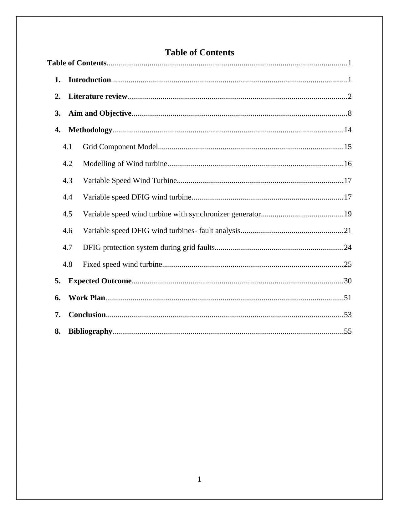
Table of Contents
Table of Contents...........................................................................................................................1
1. Introduction.........................................................................................................................1
2. Literature review................................................................................................................2
3. Aim and Objective..............................................................................................................8
4. Methodology......................................................................................................................14
4.1 Grid Component Model...............................................................................................15
4.2 Modelling of Wind turbine..........................................................................................16
4.3 Variable Speed Wind Turbine.....................................................................................17
4.4 Variable speed DFIG wind turbine.............................................................................17
4.5 Variable speed wind turbine with synchronizer generator..........................................19
4.6 Variable speed DFIG wind turbines- fault analysis....................................................21
4.7 DFIG protection system during grid faults..................................................................24
4.8 Fixed speed wind turbine............................................................................................25
5. Expected Outcome............................................................................................................30
6. Work Plan..........................................................................................................................51
7. Conclusion.........................................................................................................................53
8. Bibliography......................................................................................................................55
1
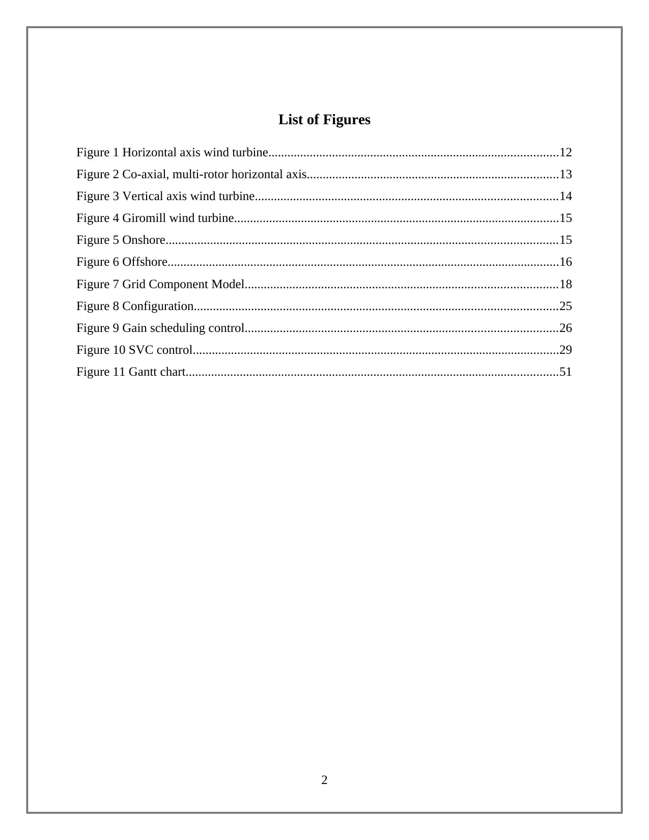
List of Figures
Figure 1 Horizontal axis wind turbine...........................................................................................12
Figure 2 Co-axial, multi-rotor horizontal axis...............................................................................13
Figure 3 Vertical axis wind turbine...............................................................................................14
Figure 4 Giromill wind turbine......................................................................................................15
Figure 5 Onshore...........................................................................................................................15
Figure 6 Offshore...........................................................................................................................16
Figure 7 Grid Component Model..................................................................................................18
Figure 8 Configuration..................................................................................................................25
Figure 9 Gain scheduling control..................................................................................................26
Figure 10 SVC control...................................................................................................................29
Figure 11 Gantt chart.....................................................................................................................51
2
⊘ This is a preview!⊘
Do you want full access?
Subscribe today to unlock all pages.

Trusted by 1+ million students worldwide
1. Introduction
The Electric power will be generated from the renewable energy, an example of which is
wind energy. The DigSilient software will simulate the power system. Electric Power Systems is
a complicated and complex structure. The electricity grid will be inserted into the whole
structure. At current situation, the requirement for the electric power is increased in the world.
For providing the power with low Carbon Emissions, this renewable energy is utilized. Electric
Power System comprises of many functions like the evaluation of the flow of load flow,
evaluation of the short path and fault, earthlings revisions, switchover voltages and insulation
organization. It is normally utilized for the production of the electrical energy. The power system
creates efficient and low-cost electricity. It has the components for the distribution and
transmission of electricity to the consumers. This power system has some of the major
components like transformers, power stations, alternators, circuit breakers, bus bars and auxiliary
devices. Nowadays, the power is generated by utilizing renewable energy like sunlight, wind,
tides, rain, waves and various type of biomass. This renewable energy helps in the reduction of
the carbon segregations, purification of the air, protection of the health of human from the
pollution and saving the functions of earth. Being inexhaustible in nature, the energy is produced
from the natural resources and is never depleted. It can also be used instead of fossil fuels and
thus can be termed as eco friendly in nature. Power generation is done by one of the important
renewable energy, wind. Apart from being eco friendly, wind energy is inexpensive and follows
a simple procedure for power generation. Moreover, this energy is also utilized for all types of
practical uses like charging batteries, pushing water and crushing grain. The kinetic energy from
the wind is utilized for the generation of mechanical power, which also provides benefits to both
economy and environment. Power analysis is performed by utilizing inexpensive software
known as Dig SILENT. The main functions of this software include handling of data, better
improved workflow and modeling capabilities. Moreover, it also helps in the reduction of the
execution cost of project and training requirement. The operating process of Dig SILENT is
extremely easy. It is also used in high-end applications like circulated generation, wind power
and handling process of large Power Systems. The electricity grid acts as a mediator network for
delivering electricity from producers to the consumers. For the production of electrical power
1
Paraphrase This Document
Need a fresh take? Get an instant paraphrase of this document with our AI Paraphraser
generator stations are present. The High Voltage Transmission Lines are utilized for carrying the
power from the reserved sources to the requested centers. The combination of minor wind
systems does not make any major operational complications, which regularly maintains the
energy and reliability of supply network. When the large combination of the wind system is
pointed at the network the critical operational complications is created. When one connects many
wind farmhouses into similar substation, the created topology will be more critical and complex.
For the reduction of this problem, the analysis will be made on the troubles. The disturbances
that are created at the large wind farm will be short circuits and wind gusts.
2. Literature review
According to the author (Amora and Bezerra, 2017), VSCF i.e. DFIG speed idle frequency
wind power transmission system is modeled. It involves wind wheel dynamic, generator
dynamic, wind variation, power system and drive train. The DFIG wind power system design
parameters simulate the entire system. For simulating the entire system, mat lab Simulink tools
are used. The DFIG wind power system design parameters are simulated by the prototype FD61-
1000. In power system, the variable speed idle frequency, the functional feature is revealed.
Under the wind variation condition, the influence of another load is also revealed. The
integration of wind energy into the grid is the major aspect of power generation of wind. The
undesired fluctuation of power into the grid is produced by wind resource. It is produced during
the utilization of fixed speed wind turbine. The stall wind turbine is extremely popular. We have
used two types of wind turbines. The two types of VSCF namely direct drive gearless permanent
magnetic generation system and generator system. Because of the low cost of the control system,
the former machine is famous. Enhancement of power capacity is the advantage in the offshore
wind park. The rotor blade drives the wounded rotor asynchronous machine via the gearbox.
Through the pad mount transformer and main circuit contractor, generator stator winding
connects to the grid. For regulating the output power, it provides excitation to rotor winding.
Based on IGBT, the regulation of output power is done by utilizing Pulse Width Modulation
Converter. In the overrated field of output power, hydraulic unit driven pitch system behaves like
a power limiter. Lastly, under the wind variation condition, we got the output for speed idle
frequency wind turbines impacts on the power system as well as load.
2
According to the author (Chen, 2017), the development of wind power industry is increased.
This is increased because many wind farms are linked into the power system. Some of the
challenges of this system include system control and operation, power quality, and system
stability. The wind farm combination into the power system introduces these significant
challenges. The modern power system of wind proposes the wind turbine requirements.
The author (Boutsika, Stavros, and Papathanassiou, 2017) states that, for the distributed
generation interconnection, consideration of fault level might be an inhibiting factor especially at
the medium level of voltage. For the calculation of the fault level result, IEC 60909 latest edition
standard is applied. This standard is applied to distributed generation in the network of low and
medium voltage level distribution. For the case studies of distributed generation, IEC calculation
methods normally involve entire related equations. The fault of grid contribution of several
distributed generation types is discussed. It involves the entire relative types of distributed
generation sources. For the reduction in the level of fault, the potential measure is included. The
system has some leading features for short circuit current. The emphasis is fixed on upstream
system contribution. The networks for distribution are featured by short circuit capacity design.
We are used desirable peak fault current relates to switchgear, construction and the equipment
mechanical and thermal withstand capacity. The net level of fault is calculated by blended short
circuit contribution of distributed generation and upstream grid. For the newly distributed
generation installation interconnection, the control is usually the most preventing factor. The
voltage transformer short circuit impedance calculates the upstream grid fault current
contribution and the determination of the low voltage and medium voltage radial network. For
improving the network overall power quality performance and voltage regulation, low voltage
should be selected. Therefore, the existing distribution network short circuit capacity is close to
design value. For the protection and coordination of switchgear, the short circuit calculations are
performed. The performance is based on the establishment of international and national
practices. The accepted standards are ANSI or IEEE and IEC. In this paper, we have applied
60909 IEC standard. This standard encompasses the configurations, several network voltage
levels, load equipment and functioning conditions. Although it focuses on conventional power,
system paradigm has large centralized traditional generators. No specific guidelines are provided
on fault contribution of medium and small size distributed generation installation. The twofold
one is the main objective. It gives concise and easy output. It is utilized for evaluating the fault
3
⊘ This is a preview!⊘
Do you want full access?
Subscribe today to unlock all pages.

Trusted by 1+ million students worldwide
level in low voltage and medium voltage radial distribution network and the point where the
distributed generator is connected. This even includes recommendations, which are used for the
purpose of fault current input for the several kinds of distributed generations.
The author (Afifi et al., 2017) states that in the network of distribution, the generation has
varied conventional short circuit capacity and downstream power flow concept. The distribution
generation can be connected even without implications. There are various disadvantages of this
distributed generation connection like the enhancement of voltage profile, overreaching network
short circuit level. It might restrict the link to the grid. Evaluation of the network is done on the
basis of IEEE thirteen bus test system by software called ETAP. The unbalanced and balanced
faults are included.
The author (Bazilian, Denny and O’Malley, 2017) tells that due to its relative isolation, the
dependency of fuel import, size, and infrastructure of the grid, Ireland facing the critical period
in the form of robust RE policy. The colloquium title on the technical challenge of enhancing
wind energy dispersion is followed. It encompassed discussion on the studies of the requirements
of grid, wind penetration and wind farm design and modeling. The electricity system present
state the status of electricity market and imposes into the view of the technical problems that are
required to be solved for the enhancement of the wind penetration.
According to the author (El-Zonkoly, 2017) in distribution power system, the distributed
generation penetration could affect the characteristics and the conventional fault current level.
The conventional arrangements for protection, which is developed in the distribution utilities, are
complex. The reclosing procedure could be influenced. In the distribution system, reclosing
scheme and the protection coordination based on data exchange and communication and
automation technology could be realized with rapid developments. In the power distribution
networks, for fault diagnosis, the multi-agent on the basis of the scheme has given. The
distribution network is provided by various sections. Relay agents measure the bus current. It can
classify and detect the faults. It even determines the location of the faults. The wavelet
coefficients entropy techniques are used. The proposed protection producer’s performance is
tested via simulations. There are two systems. One is practice sixty-six-kilo volt system and the
other one is benchmark MV distribution system.
4
Paraphrase This Document
Need a fresh take? Get an instant paraphrase of this document with our AI Paraphraser
According to the author (Das and Santoso, 2017), the wind speed variation effected by the
wind turbine is investigated. The wind turbine provides fault current, which is six times higher
the limited current. The speed of the wind variation impacts the generator internal voltage. When
the inner voltage of the generator is high, fault current becomes high while the fault happens.
When the internal voltage is low, the corresponding short-circuit current is also low. The main
objective is to investigate the importance of the fault current variation in corresponding to the
security device setting. It is even calculated from the standard IEC60909.We conducted 5
comprehensive studies. The minimum and the maximum fault current are determined by 60909
IEC standards for each of the case studies. At various wind speeds, it is compared with the
simulation output.
According to the author (Safigianni, Koutroumpezis, and Spyridopoulos, 2017), in large-
scale MV power distribution networks, the DG penetration results are examined. The 3 power
substations feed 21 lines. From the photovoltaic units, the injected power came. According to the
national and international standards, DG influence on network branch I (current), V (voltage)
profile, losses and in feeding substations short circuit range at MV bus bar, is examined. We
proposed the technical solutions. We explored arising issues. This is related to the application for
the pilot. The conclusion concerned about extended DG penetration is set out in real power
network distribution.
According to the author (Muljadi et al., 2017), WPP consisting of many turbines, which is
interconnected through the underground cable. Each turbine is linked to the transformer, which
increases the generating voltage and has the range of 690 V to MV. In wind power plant, under
fault conditions, the effect of current on transmission network is evaluated. It is an extremely
challenging task to protect the engineers because of the differences in topology. These topology
differences are in between the typical generating units and wind turbine generators. For various
types of fault conditions, the wind power plant behavior is investigated. It also investigates
configuration of the transformer, relative compensation capacitor, and the impact of wind turbine
type. We discovered the response of voltage at the various buses. Along with the symmetrical
components, the short-circuit line I (current) is proposed.
The author (Chen, 2017) states that the rapid development of wind power industry many
wind farms IS are combined together with the power systems. Few challenges are presented
5
because of the wind farm combination with the power system. The challenges are listed as power
quality, the stability of system and system control and operation. The modern wind power device
is described. The wind turbine connection requirements and control methods for meeting the
specifications are discussed below.
The author (Amora and Bezerra, 2017) states that the attained transient stability results while
computing wind farm connection effects in the power system. The software is developed for the
stability simulation in MATLAB, which is a user friendly interface. It permits to execute in
various cases such as conventional generation loss, SC in the network, function under wind gust,
load reduction, operation under turbulent wind and sudden wind farm disconnection. The
simulation results used to evaluate stability effects of wind farm integration, test power system
into the electric grid.
The author (Potamianakis and Vournas, 2017) states that the methodology for the
simplification of the distribution network is presented. This methodology consists of a number of
wind farms provided with medium voltage lines and induction generators. The methodology is
created for the indefinite equivalent network. It even consists of equivalent medium voltage
feeder and equivalent wind farm. The analyzed power system complexity is reduced by the
methodology, which is proposed. It leads to accelerating simulation time and permitting several
applications. The applications are listed with limited resources, stability analysis, and security
assessment. Through its application, methodology validation is determined by karystos
distribution network in Evia Island and entire network of Evia Island. We simulated the response
as well as minimized the network under same contingency. We compared the results of
simulation. By utilizing MATLAB or Simulink, the performance of the simulation is checked. In
NTUA, the software package is developed. It is suitable for stability analysis and simulation of
the small-interconnected power system.
According to the author (Afifi et al., 2017), in distribution networks, DG penetration has
changed the conventional concept of SC capacity and downstream power flow. Without
implications, DG can be connected in some instant. Connection of DG even has some of the
major disadvantages. The main disadvantages include exceeding SC level in network and voltage
profile enhancement. It even restricts the DG connection to the network. The DFIG wind
6
⊘ This is a preview!⊘
Do you want full access?
Subscribe today to unlock all pages.

Trusted by 1+ million students worldwide
turbines impact on IEEE thirteen bus distribution test system SC level by the software is known
as ETAP. It involves unbalance and balance faults.
The author (Gohil, Mehta and Vora, 2017) states that, in power system, the SC current
calculation of the equipment is most significant. The calculation of SC current is for suitable
relay features selection and CB for system protection. The power system is changed because of
RE source large-scale penetration on the conventional system,. The solar and the wind energy
sources are the RE sources that are involved in the turbine. The various types of generator supply
the wind energy. When compared to the conventional synchronous generator, the DFIG is the
common type generator that provides different behavior. The DFIG SC current contribution is
determined analytically. It is validated by EMTDC or PSCAD software under different wind
speed. It is even validated concerning distinct output of the generator voltage drop.
The author (Margossian and Sachau, 2017) states that SC programs with typical calculation
are not considered as the general behavior of inverter based on DG. With the combination of the
techniques, various tools are to be developed. The technique that is used accommodates inverter,
which is based on distributed generator having various fault response and standard SC
calculation tools. By using model named realistic test distribution network, the technique is
compared with other techniques and evaluated.
According to the author (Kazachkov, Feltes and Zavadil, 2017), the wind energy conversion
system includes electrical and mechanical equipment as well as their control. For the simulation
of power system stability, the system modeling needs the cautious examination of equipment. It
also requires control to evaluate the characteristics which his significant in bandwidth and
timeframe. The characteristics are most significant for the design of wind or turbine farm. For
simulation package for stability and for effective PS load flow. The electrical, air-dynamical and
mechanical factors are modeled. Dynamic models with their control represent the various types
of variable speed and constant speed technologies. The load flow model permits the wind farm
aggregation consisting of 10-100's of the wind turbine unit.
According to the author (Huda and Živanović, 2017), in recent years, the DG integration into
distribution network has obtained in terms of efficiency and reliability improvement. Various
technical problems might occur because of the enhancing distributed generation penetration.
These challenges include power quality, protection problems, and voltage control. In order to
7
Paraphrase This Document
Need a fresh take? Get an instant paraphrase of this document with our AI Paraphraser
examine the distributed generation impacts on the distribution system, extra components required
to model with the typical component of the distribution system. The aim is to analysis distributed
system impacts on system function, challenges mitigation; system components needed model,
associated regulation and standard for distributed systems successful function. The number of
open source and typical tools is presented for distribution systems analysis and model. For
analyzing the enhanced distribution generation penetration impacts, the conceptual
computational tool is involved.
3. Aim and Objective
To generate the electrical power at the wind farm, the wind is used as a source. The wind is
supplied to the electrical generator to generate the higher voltage. The electrical generators used
at the wind farm are to be induction generators. Wind is used instead of the diesel engine, to
produce the higher voltage. The transformer helps in improving the wind farm voltage. The
transmission and distribution voltage depends on the interconnection type. The voltage produced
at the wind farm depends on the wind speed. Due to the high speed of the wind, the higher
voltage is created. Sometimes the high wind short-circuits the network. It creates the much
amount of heat and mechanical damage to human beings. The short circuit is also occurred by
increasing current in the system. It provides damage to the system. The short circuit is present in
the form arc. It breaks the conductor for a long time. Many types of fault occurred due to the
short-circuiting. The fault creates the variety of responses for the wind turbine types. The fault
occurred at wind turbine due to the short-circuiting. The faults are to be the 3LG fault, SLG fault,
and LL and LLG faults.
Wind Turbines
Wind turbines ride on a pinnacle to get energy from the breeze. The higher the edges are, the
more they can exploit speedier and less turbulent breeze. The breeze turbine includes 3 portions.
They are sharp edges, shaft, and generator:
1) Blades: It drives boundaries to a breeze. When the breeze powers cutting edge to move, a part
of breeze vitality is exchanged to the rotor in that portion.
2) Shaft: The pole is additionally twisted during rotor turns and exchanges the mechanical energy
into rotational energy.
8

3) Generator: It utilizes the difference in electrical charge to provide alteration in voltage. The
voltage leads the electric current by the cables for appropriation. The Horizontal axis is one
type of wind turbines. It is commonly used one. The blades, generator, and shaft are placed at
the top of the tower. Blades face the wind. The shaft is placed to be horizontal to the ground.
Advantages
1) It provides the stability to the system because the blades are placed in the center of gravity at
the turbines side (Tsai, Lin, and Tseng, 2017).
2) It has the Skill to arm warp that provides the blades to take the best angle of attack
3) Tall pinnacle allows access to grounded breeze with wind shear
4) Tall pinnacle permits situation on uneven land or in seaward areas
5) Can be sited in woods above tree-line
6) Most are self-beginning
Disadvantages
1) Trouble operating in nearby ground breezes
2) Problematic to carriage (20% of equipment costs)
3) Problematic to fix (require tall cranes and skilled operators)
4) Effect sensor on nearness
5) Local obstruction to aesthetics
6) Problematic in maintenance
The impact of creating electric power at the wind turbine are Emissions Reduction,
Electricity Amount and Energy balances are perfect, It provides security and reliability of
supply, It requires high power, The mixing of fuel is affected, It provides the effect on the
electricity market. It affects the Inter-TSOs electricity trading due to excess of wind power (Pillai
et al., 2017). Totally three types of wind turbines are present there. The horizontal axis turbine is
commonly used one. The components of that turbine are pitch, shaft, gearbox, generator,
controller, Anemometer, nacelle, wind vane, high-speed shaft, tower, blades, yaw motor, Yaw
drive, Brake, Rotor (Zheng and Kezunovic, 2017).
Types of wind farm
9
⊘ This is a preview!⊘
Do you want full access?
Subscribe today to unlock all pages.

Trusted by 1+ million students worldwide
1 out of 75
Related Documents
Your All-in-One AI-Powered Toolkit for Academic Success.
+13062052269
info@desklib.com
Available 24*7 on WhatsApp / Email
![[object Object]](/_next/static/media/star-bottom.7253800d.svg)
Unlock your academic potential
Copyright © 2020–2026 A2Z Services. All Rights Reserved. Developed and managed by ZUCOL.


