EAC4024-N: DGA Based Asset Management Report on Transformers
VerifiedAdded on 2023/06/14
|18
|3636
|493
Report
AI Summary
This report provides an analysis of Dissolved Gas Analysis (DGA) results from 10 units of 132/66kV, 90MVA transformers to assess their operational condition. It begins with a general theory of transformer insulation, cellulose decomposition, and oil decomposition. The technical analysis involves interpreting a four-level criterion and applying individual gas and Total Dissolved Combustible Gas (TDCG) methods, as well as Roger’s Ratio, to the DGA results. The report evaluates whether the transformers have operational problems, identifies the nature of these problems, and determines if the transformers should remain in service. Recommendations are made based on the analysis, with a conclusion summarizing the findings and potential consequences associated with the DGA results. The goal is to provide insights into condition management of transformers to avoid unplanned failures.
Running Head: Asset Management Report 1
Asset Management Report
Name
Institution
Professor
Course
Date
Asset Management Report
Name
Institution
Professor
Course
Date
Paraphrase This Document
Need a fresh take? Get an instant paraphrase of this document with our AI Paraphraser
Asset Management Report 2
Executive Summary
Transformers constitute some of the most critical electric apparatus in the electrical power
systems and are beneficial for providing reliable energy flow. Organization must therefore
ensure they continuously monitor their transformers in order to identify any potential faults. To
this end, condition assessment and management of transformers should be prioritized in any
electric power organization. Condition management therefore involves choosing the appropriate
monitoring tools for transformers to avoid unplanned failures as well as lowering maintenance
and replacement cost. In this report, we shall be interpreting the results of dissolved gas analysis
obtained from 10 units of transformed rated 132/66kV and 90MVA. Since there are no historical
data of dissolved gas analysis in 132kV transformers, we shall assume that they exhibit the same
or similar characterized to those of the already existing data. We shall investigate whether the
transformer have any operation problems as indicated from the DGA results. Moreover, we shall
identify the nature of the problem and if it is witnessed in one transformer or all the transformers.
From the analysis of the results we shall determine whether the transformers should remain in
service as well as whether the exhibited problem is expected to escalate. Upon investigating and
evaluating the data, we shall establish the possible consequences that can be associated with the
DGA results.
Asset Management Report 3
Table of Contents
Introduction.................................................................................................................................................4
General Theory............................................................................................................................................4
Transformer Insulation............................................................................................................................4
Decomposition of Cellulose....................................................................................................................5
Decomposition of Oil..............................................................................................................................5
Technical Analysis......................................................................................................................................6
Interpretation of Four-Level Criterion.....................................................................................................6
Analysis of DGA Results using Individual Gas and TDCG Method.......................................................7
Analysis Using Roger’s Ratio................................................................................................................11
Recommendations.....................................................................................................................................11
Conclusion.................................................................................................................................................12
References.................................................................................................................................................13
Appendices................................................................................................................................................15
⊘ This is a preview!⊘
Do you want full access?
Subscribe today to unlock all pages.
Trusted by 1+ million students worldwide
Asset Management Report 4
Introduction
Malfunction in oil-filled transformers can be assessed by detection of certain key gases which
might be present in the transformer oil and collected Buchholz relay. Sampling and analysis of
these gases is essential in testing and evaluating the health of a transformer. Formation of gases
within operating transformers is caused by either thermal or electrical disturbances and if not
corrected may result to system failure. The electrical disturbances may be categorized as corona
or electrical arc (HARLOW, 2012, p.188-90). The interpretation of the test data is upon the basis
of the type of individual gases liberated and their quantity present in the transformer (GILL,
2009, p.203-210).
General Theory
Transformer Insulation
Electrical equipment and apparatus use fluids and insulating oils as dielectrics. Mineral oils and
synthetic fluids are used in transformers since they are less flammable (GILL, 2009, p.203-210).
Effectiveness of insulating fluids is adversely affected by their deterioration which is brought
about by overheating, oxidation, contamination and electrical stress. High temperatures from
environmental conditions or from increased load are responsible for accelerating the
deterioration process (IEEE, 2009, p.3; HARLOW, 2012, p.188-90). Therefore, to guarantee
continued service, maintenance, and safety, a condition monitoring or testing program
comprising of chemical and electrical analysis is essential for the dielectrics (PURKAIT, 2017,
p.211-15; SCHRIEBER, WILLIS & PHILIPS, 2012, p.203-07). Mineral oils (hydrocarbon oils)
have high chemical stability and dielectric strength which enables them to be used as transformer
Paraphrase This Document
Need a fresh take? Get an instant paraphrase of this document with our AI Paraphraser
Asset Management Report 5
insulating fluid. Sampling of oil in the transformer and regular inspection is necessary to ensure
that the transformer oil is free of contaminants (GILL, 2009, p.203-210).
Decomposition of Cellulose
An insulation system for an oil-immersed transformer comprises of cellulose and insulating oil
materials (HARLOW, 2012, p.188-90). Normally, this insulation degrades and produces certain
flammable and non flammable gases. However, their presence becomes further evident if the
transformer dielectric is subjected to elevated temperatures (Sun, Huang and Huang, 2012,
p.1220-25). Thermal decomposition of cellulose insulation at temperatures of 140 0C liberates,
carbon dioxide (CO2), carbon monoxide (CO), and some methane (CH4) or hydrogen (H) (TANG
& WU, 2011, p.125-26). The frequency at which the key gases are emitted is exponentially
dependant on the temperature as well as proportionally aligned to quantity of the insulation at the
temperature (GILL, 2009, p.203-210; PURKAIT, 2017, p.211-15).
Decomposition of Oil
Thermal decomposition of oil between 150oC and 500oC liberates large volumes of methane and
hydrogen gases, and traces of ethane and ethylene (IEEE, 2009, p.3; Ward, 2003, p.463-68).
Higher oil temperatures results to more hydrogen gas been emitted than methane as well as
higher capacities of ethane (C2H6), and ethylene (C2H4) (LOO & ZULKURNAIN, 2014, p.48;
GILL, 2009, p.203-210). Increased volumes of hydrogen and ethylene are liberated as the
temperatures rise (IEEE, 2009, p.3). Partial discharges (corona) and low-intensity arcing emits
mainly hydrogen gas coupled with minimal volumes of methane (CH4) and traces of acetylene
(C2H2) (GILL, 2009, p.203-210). Acetylene gas becomes more pronounced during high-intensity
arcing which occurs at (700oC – 1800oC) inside the transformer tank (TANG & WU, 2011,
p.125-26; PURKAIT, 2017, p.211-15)
Asset Management Report 6
Technical Analysis
Detecting, analyzing and identifying of individual gases dissolved in transformer oil can be of
great importance while evaluating the operating condition of an oil-impregnated transformer
(Ahmed, Hassan, Ahmed & Kassir, 2016, p.35; GILL, 2009, p.203-210; SCHRIEBER, WILLIS
& PHILIPS, 2012, p.203-07). Baseline data is necessary for establishing a reference point for
newly adopted transformers for comparison with subsequent routine maintenance sampling
results (Morais and Rolim, 2006, p.673-80; Huang, 2003, p.1257-61). However, monitoring and
assessment of the transformer condition can commence at anytime even if the reference data is
not available (GILL, 2009, p.203-210). The two methods for investigating the key gases
liberated include Dissolved Gas Analysis (DGA) and Total Combustible Gas Analysis (TCGA).
Inspection of the individual gases present in oil gives a convenient tool for testing the
functionality of the transformer (CHAKRAVORTI, DEY & CHATTERJEE, 2013, p.118-22).
DGA method of investigating flammable gases is more informative than TCGA method as it
provides the earliest probable diagnosis of any abnormality in the transformer. On the contrary,
TCGA is widely applied and fast in continuously monitoring the health of a transformer (GILL,
2009, p.203-210; ELLEITHY, 2010, p.226-28). However, the demerit associated with TCGA is
that it gives a single value of the oil-combustible gases hence not quantifying the individual
gases present in the oil (Sun, Huang and Huang, 2012, p.1220-25). Additionally, it is important
to note that temperature and pressure affects solubility of the gases in oil.
Interpretation of Four-Level Criterion
Detection of the key gases at the earliest possible time as well as undertaking the appropriate
measures to rectify the transformer condition leads to the success of the fault gas analysis
(SCHRIEBER, WILLIS & PHILIPS, 2012, p.203-07). The four-level criterion developed by
⊘ This is a preview!⊘
Do you want full access?
Subscribe today to unlock all pages.
Trusted by 1+ million students worldwide
Asset Management Report 7
IEEE for classifying risks in transformers is crucial for analyzing condition of a transformer if no
previous dissolved gas history for transformers exists (IEEE, 1992, p16). This criterion applies
both concentrations for individual gases and concentrations of all combustible gases. Since we
have no prior dissolved gas history for the 10 installed transformer units, we shall adopt this
criterion in establishing the risks that may be facing the transformers.
Condition 1: TDCG under this quantity shows that the transformer is working normally or
satisfactorily. Individual combustible gases above specified limits should elicit further analysis
or investigation (IEEE, 1992, p.9-12).
Condition 2: The normal combustible gas level has been exceeded. All combustible gases above
the specified limits should give rise to additional investigation. Further measures ought to be
undertaken to establish trends. There is high probability that faults might be present in the
transformer (IEEE, 1992, p.9-12).
Condition 3: TDCG at this limits suggest increased level of decomposition. Further analysis
should be carried out for each individual flammable gas exceeding its specified. Quick response
is desirable to establish trend. There is possibility of faults in the transformer (IEEE, 1992, p.9-
12).
Condition 4: This level indicates extreme decomposition of oil or cellulose insulation. Unit must
be changed since further operation of the transformer may result to its failure. Need to retest. If
both the individual and TDCG gases are rising significantly (>30ppm/day), transformer should
be de-energized. The fault is active (IEEE, 1992, p.9-12).
Analysis of DGA Results using Individual Gas and TDCG Method
Transformer A1
Paraphrase This Document
Need a fresh take? Get an instant paraphrase of this document with our AI Paraphraser
Asset Management Report 8
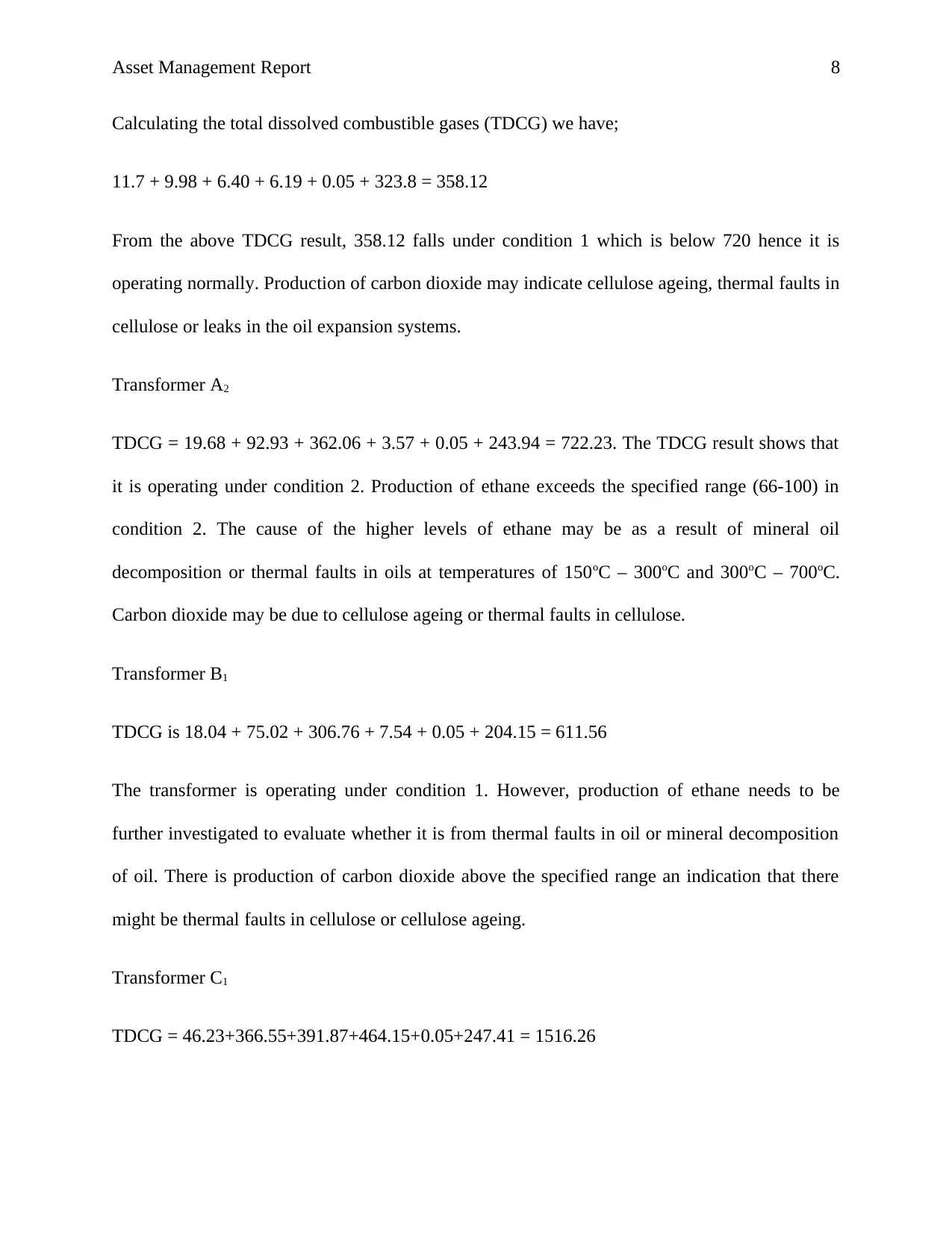
Calculating the total dissolved combustible gases (TDCG) we have;
11.7 + 9.98 + 6.40 + 6.19 + 0.05 + 323.8 = 358.12
From the above TDCG result, 358.12 falls under condition 1 which is below 720 hence it is
operating normally. Production of carbon dioxide may indicate cellulose ageing, thermal faults in
cellulose or leaks in the oil expansion systems.
Transformer A2
TDCG = 19.68 + 92.93 + 362.06 + 3.57 + 0.05 + 243.94 = 722.23. The TDCG result shows that
it is operating under condition 2. Production of ethane exceeds the specified range (66-100) in
condition 2. The cause of the higher levels of ethane may be as a result of mineral oil
decomposition or thermal faults in oils at temperatures of 150oC – 300oC and 300oC – 700oC.
Carbon dioxide may be due to cellulose ageing or thermal faults in cellulose.
Transformer B1
TDCG is 18.04 + 75.02 + 306.76 + 7.54 + 0.05 + 204.15 = 611.56
The transformer is operating under condition 1. However, production of ethane needs to be
further investigated to evaluate whether it is from thermal faults in oil or mineral decomposition
of oil. There is production of carbon dioxide above the specified range an indication that there
might be thermal faults in cellulose or cellulose ageing.
Transformer C1
TDCG = 46.23+366.55+391.87+464.15+0.05+247.41 = 1516.26
Asset Management Report 9
This lies between the range (721 and 1920), under condition 2. The production of methane,
ethylene, ethane and carbon dioxide exceeds the specified limits. Methane production may be
due to thermal faults in oils at 1500C, 300oC or 700o; decomposition of mineral oils and partial
discharge. Ethylene may be due thermal faults in oils at 700oC, mineral decomposition of oil and
arcing.
Transformer C2
TDCG = 150.81+365.87+183.97+899.42+6.48+35.72 = 1642.27.
This transformer is operating under condition 2. Investigation of some of the key gases such as
hydrogen, methane, ethane, ethylene and acetylene must be carried out to test the abnormality in
this transformer. Carbon dioxide and carbon monoxide are below the specified limits in
condition 1 and condition 2. The faults associated from emission of those key gases may be due
to thermal faults in oil, mineral decomposition of oil, arcing and partial discharge.
Transformer D1
TDCG = 12.86+55.84+233.14+5.47+0.79+192.49 = 500.59. This transformer operates under
condition 1. Emission of ethane is above the specified limit meaning there might be a thermal
fault in the oil or decomposition of mineral oil. Carbon dioxide mission is normal meaning that
no minimal ageing in cellulose and thermal faults in cellulose.
Transformer D2
TDCG = 25.04+134.39+637.14+23.67+0.05+218.5 = 1038.79.
The value for the TDCG is in condition 2. Ethane exceeds the specified level. This may be as a
result of thermal faults in oils or decomposition of mineral oils.
⊘ This is a preview!⊘
Do you want full access?
Subscribe today to unlock all pages.
Trusted by 1+ million students worldwide
Asset Management Report 10
Transformer D3
TDCG = 17.86+123.22+582.37+25.27+0.59+199.96 = 949.27.
Operation of the transformer is in condition 2. Investigation of ethane needs to be carried out to
establish the cause that may be leading to its high emission. Thermal faults in oils and
decomposition of mineral oil are the probable causes that are responsible for its high emission.
Transformer E1
TDCG = 13.75+86.17+350.73+5.35+0.05+127.26 = 583.31.
Transformer is operating under satisfactorily under condition 1. Carbon dioxide in the gas lies
with the expected normal value but ethane presence in the oil is beyond the specified limit.
Investigation of its high presence in the oil may indicate thermal faults in oil or decomposition of
the mineral oil.
Transformer E2
TDCG = 15.95+94.17+223.02+8.85+0.05+201.2 = 543.24.
This indicates that the transformer is operating satisfactorily under condition 1. The carbon
dioxide level is within the normal limit but ethane level exceeds the specified limit. This may be
due to thermal faults in oil and decomposition of mineral oil.
CO2/CO ratio can be used to analyze the health of an oil-immersed generator. However, for the
ratio to be significant; the individual gases, that is, both CO2 and CO, should be above 5000/500
ppm. For this reason, we shall not apply this ratio in investigation (IEC, 2015, p.12).
Paraphrase This Document
Need a fresh take? Get an instant paraphrase of this document with our AI Paraphraser
Asset Management Report 11
Analysis Using Roger’s Ratio
For transformer C2,
R1= 365.87/150.81 = 2.426, R2= 6.48/899.42 = 0.0072, R5= 899.42/183.97 = 4.889
From Roger’s ratio, see appendices – Table 2, the fault associated with this ratio is thermal at
700oC. Additionally, from the DGA Interpretation Table; see Appendices – Table 4, the ratio of
C2H4/C2H6 in transformer C2 is 4.889. Since the ratio is >1, it indicates that there is thermal fault
in oil.
Recommendations
Following the observations from the analysis of the DGA results, it can be seen that there is a
thermal fault in oil witnessed in all the transformers except in transformer A1 where all the key
gases are within the specified limits. The thermal fault in oil has led to the higher presence of the
key gases in the transformers. Transformers which are working under condition 1 should be let to
continue with normal operation. These transformers include: A2, C1, C2, D2 and D3. However,
caution must be exercised while operating those transformers. Investigation and monitoring of
individual gases must be carried to ensure that unplanned faults or failures are prevented. Asset
manager team should therefore determine the load dependence of those transformers. For those
operating under condition 2, asset managers must exercise caution as well as investigation for the
individual gases. Load dependence of the transformer should be determined. Since these
transformers have not had any previous dissolved gas history, the asset managers must ensure the
frequently investigate the dissolved gases in the transformers to identify any trends in the
emission of gases. Planned investigation is vital in establishing any gas presence which might
cause unplanned failures and faults in the transformers. De-energized of transformers must also
Asset Management Report 12
be carried out if those existing show signs of failure. The nature of the problem associated with
all the transformers except transformer A1 is thermal fault in oil or decomposition in mineral oil.
However, the intensity at which emission of the key gases takes place in transformer C2 is
worrying. As a result, I would advise the asset manager team to consider replacing that
transformer.
Conclusion
Dissolved gas analysis plays a vital role in establishing the cause of gas emission in oil-
immersed transformers. Frequent investigation and evaluation of the gases emitted and the
condition of the transformer is essential in ensuring that preventive measures are taken. Such
investigations help in establishing the root cause of the presence of gases in transformer oil.
⊘ This is a preview!⊘
Do you want full access?
Subscribe today to unlock all pages.
Trusted by 1+ million students worldwide
1 out of 18

Your All-in-One AI-Powered Toolkit for Academic Success.
+13062052269
info@desklib.com
Available 24*7 on WhatsApp / Email
![[object Object]](/_next/static/media/star-bottom.7253800d.svg)
Unlock your academic potential
Copyright © 2020–2026 A2Z Services. All Rights Reserved. Developed and managed by ZUCOL.