AUR40816 Diesel Engine Testing, Hazards, and System Components

Verified

Added on  2022/09/28

|6
|1273
|38
Report
AI Summary
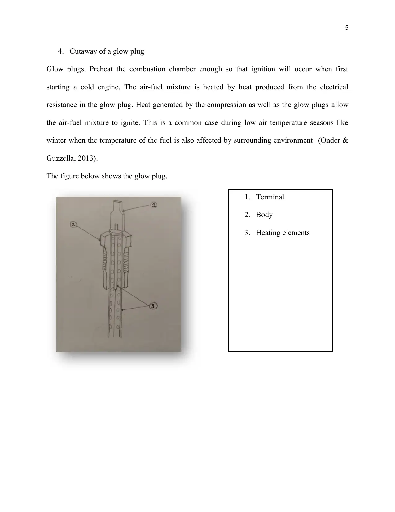
This report provides a comprehensive overview of diesel engine testing procedures, focusing on the national Environment Protection (Diesel Vehicle emission) Measure. It outlines the dynamometer testing process, detailing the phases from engine idling to acceleration and braking. The report also emphasizes the dangers associated with working with diesel, including its flammability and potential health risks from exhaust fumes and skin contact. It suggests safety measures such as using respiratory protective equipment, providing staff training, improving ventilation, and implementing administrative programs. The report further explores the components of a diesel fuel system, including the fuel tank, fuel pump, filters, injection pump, injection nozzles, and glow plugs, explaining their functions and how they work together to ensure efficient combustion. References to key literature are included. This report is designed to provide students with a detailed understanding of diesel engine systems and associated safety protocols.
Document Page
Running Head: AUR40816 1
AUR8016
Student’s name
University Affiliation
tabler-icon-diamond-filled.svg

Paraphrase This Document

Need a fresh take? Get an instant paraphrase of this document with our AI Paraphraser
Document Page
2
1. Testing procedure for diesel systems as outlined by the national Environment Protection
(Diesel Vehicle emission) Measure (Denton , 2016).
The test done in a dynamometer to the fuel present in the tank during vehicle testing is as
follows.
Phase A; B; A-B: After the engine system idles, Select low gear and let it run for around 60
seconds
Phase B–C: Rapidly accelerate through gears until you achieve a speed of 80 km/h.
Phase C–D: Stop the vehicle by breaking.
Phase D-E: After the engine rests for a while, Select low gear and run it for another 60 seconds
Phase E-F: Accelerate rapidly until a speed of to 80 km/h is achieved.
Phase F-G: halt the engine by braking.
Phase G-H: Again, after the engine system rests, select low gear and run for 60 seconds.
Phase H-I: Accelerate rapidly until a speed of to 80 km/h is achieved.
Phase I-J: For about 60 seconds maintain the speed of 80 km/h.
Phase J: This completes the test. Reduce the speed and leave the vehicle engine idle.
2. Dangers of working with diesel.
Many mechanical devices are powered by diesel engines, they include Lorries, pick-up trucks,
buses among others, farm machinery and construction equipment are also powered by such
engines. The operation of all these machinery and equipment provide exposure to exhaust fumes
and sometimes in various workplaces it requires the operators to come in contact with diesel.
Diesel is a flammable substance and when brought in contact with a flame will ignite
spontaneously and therefore it is a fire hazard (Bennet , 2009). When exposed to temperatures
equal to or above 61 °C which is the flash point or self-ignition temperatures it ignites. Diesel
Document Page
3
vapors when introduced in air or heat reacts violently. This is risky for individuals working in
such conditions.
The environment suffers equally from diesel spills especially from oil tankers. This in turn harms
the soil and pollutes the water hence harming marine life, plant life and humans in general.
Carbon monoxide, a byproduct of diesel combustion destroys the ozone layer which plays a vital
role in protecting the earth’s atmosphere.
Long-term exposure to the skin may result in eczema and should be avoided. Prolonged
inhalation leads to chest tightness and breathing difficulties and irritation of the eyes
(International Agency for Research on Cancer, 2015).
The use of Respiratory Protective Equipment to protect against hazardous gas inhalation and
contact with the diesel fuel. Training and giving instruction to staff on the dangers of excessive
exposure to diesel in terms of contact and exhaust inhalation; that is identifying potential risks
and teaching on how to respond to those cases. Reducing the amount of diesel fumes in the air in
areas where diesel is handled as a result of proper ventilation. Administrative programs to
support engineering controls to ensure minimal exposure for example, encouraging turning off of
engines instead of letting them idle, as a result the amount of exhaust fumes in the air would
have been reduced especially in garages and workshops. Another initiative would be to have the
diesel storage facilities are properly labelled (Wharton , 2013).
3. Diesel fuel system consists of; the fuel tank, fuel pump, filters, injection pump and
injection nozzles. They all work together to ensure an atomized form of diesel fuel is
delivered into the engine at the precise time combustion and pressure (Bell , 2013).
Fuel tanks. Stores fuel to run the engine for a certain amount of time. It is closed to prevent
contamination by foreign particles. Air is also allowed to enter through vents, replacing any fuel
Document Page
4
supplied to the engine for combustion. Other than air vents, three openings to the tank exist with
the following instructions; fill, discharge, and drain. The diesel is usually carried from the fuel
tank into the combustion chambers using several types of fuel lines.
Fuel Transfer pump. Draws or pushes the fuel through the fuel filters for cleaning through
filtration to remove particles that would otherwise clog the injectors. This pump is driven by the
engine. Fuel is delivered here by gravity or air pressure for simple systems (Xin , 2011).
Fuel Filters. Filtration is a must for diesel fuels before they are introduced in a combustion
chamber. A classic system might have three phases of progressive filters which include a
primary and a secondary filter both preceded by transfer pump or a filter screen at the tank. The
filters can be either in parallel or series. When arranged in parallel, the fuel passes equally
through each filter and for series filters the fuel will go through them one at time.
Injection Pump. Supplies highly pressurized fuel for injection.
Injection Nozzles. Deliver atomized form of diesel fuel to the combustion chamber of every
cylinder. This highly atomized, pressurized fuel is distributed evenly throughout the cylinder has
the advantage that there is an overall increase in power and also helps in fuel economy, reduced
noise from the engine, and overall a smoother operation of the system as well (Konran , 2014).
In the combustion chamber where there is compressed air the atomized fuel mixes with it
causing it to ignite releasing massive amount of energy that turn the crank shaft thus driving the
system when the operation is continuous.
tabler-icon-diamond-filled.svg

Paraphrase This Document

Need a fresh take? Get an instant paraphrase of this document with our AI Paraphraser
Document Page
5
4. Cutaway of a glow plug
Glow plugs. Preheat the combustion chamber enough so that ignition will occur when first
starting a cold engine. The air-fuel mixture is heated by heat produced from the electrical
resistance in the glow plug. Heat generated by the compression as well as the glow plugs allow
the air-fuel mixture to ignite. This is a common case during low air temperature seasons like
winter when the temperature of the fuel is also affected by surrounding environment (Onder &
Guzzella, 2013).
The figure below shows the glow plug.
1. Terminal
2. Body
3. Heating elements
Document Page
6
References
Bell , J. (2013). Modern Diesel Technology: Electricity and Electronics. Boston : Cengage
Learning.
Bennet , S. (2009). Modern Diesel Technology: Diesel Engines. Boston : Cengage Learning.
Denton , T. (2016). Advanced Automotive Fault Diagnosis: Automotive Technology: Vehicle
Maintenance and Repair. Abingdon : Routledge.
International Agency for Research on Cancer. (2015). Diesel and Gasoline Engine Exhausts and
Some Nitroarenes. Lyon : IARC.
Konran , R. (2014). Diesel Engine Management: Systems and Components. Berlin : Springer .
Onder , C., & Guzzella, L. (2013). Introduction to Modeling and Control of Internal Combustion
Engine Systems. Berlin : Springer Science and Business Media .
Wharton , A. J. (2013). Diesel Engines. Amsterdam : Elsevier .
Xin , Q. (2011). Diesel Engine System Design. Amsterdam : Elsevier Science.
chevron_up_icon
1 out of 6
circle_padding
hide_on_mobile
zoom_out_icon
[object Object]