MEC8042 - Diesel Train Drive System: Design, Analysis & Layout
VerifiedAdded on 2023/06/12
|15
|2113
|458
Report
AI Summary
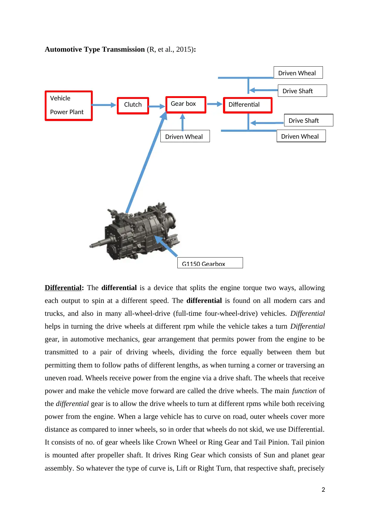
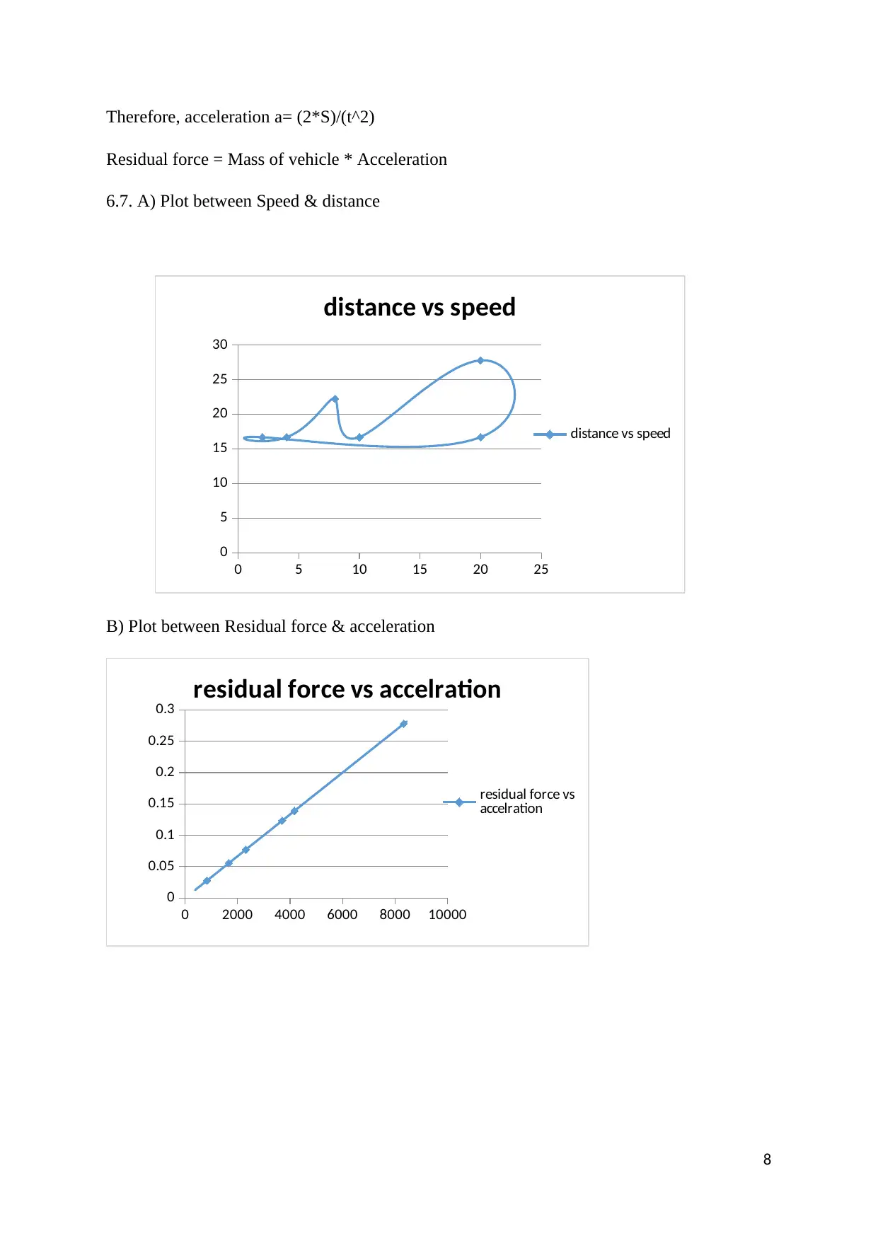
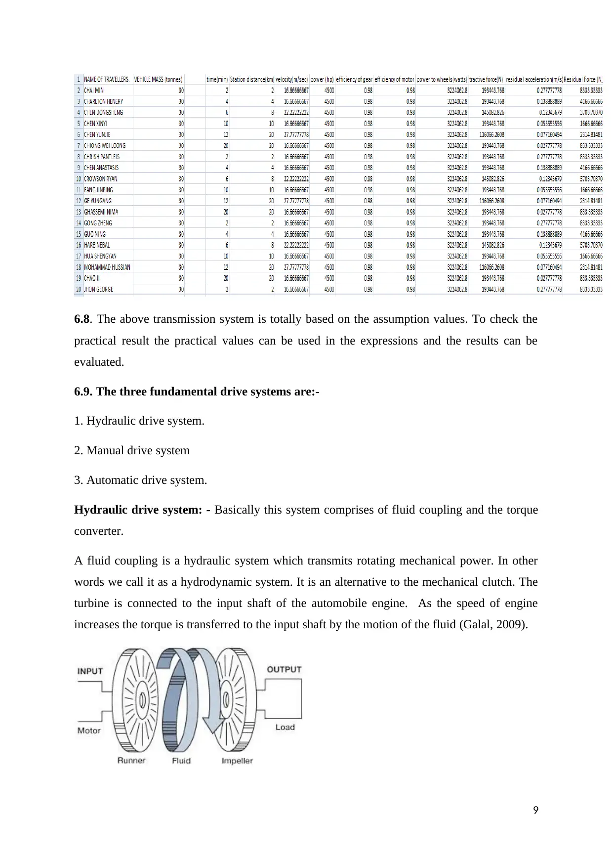
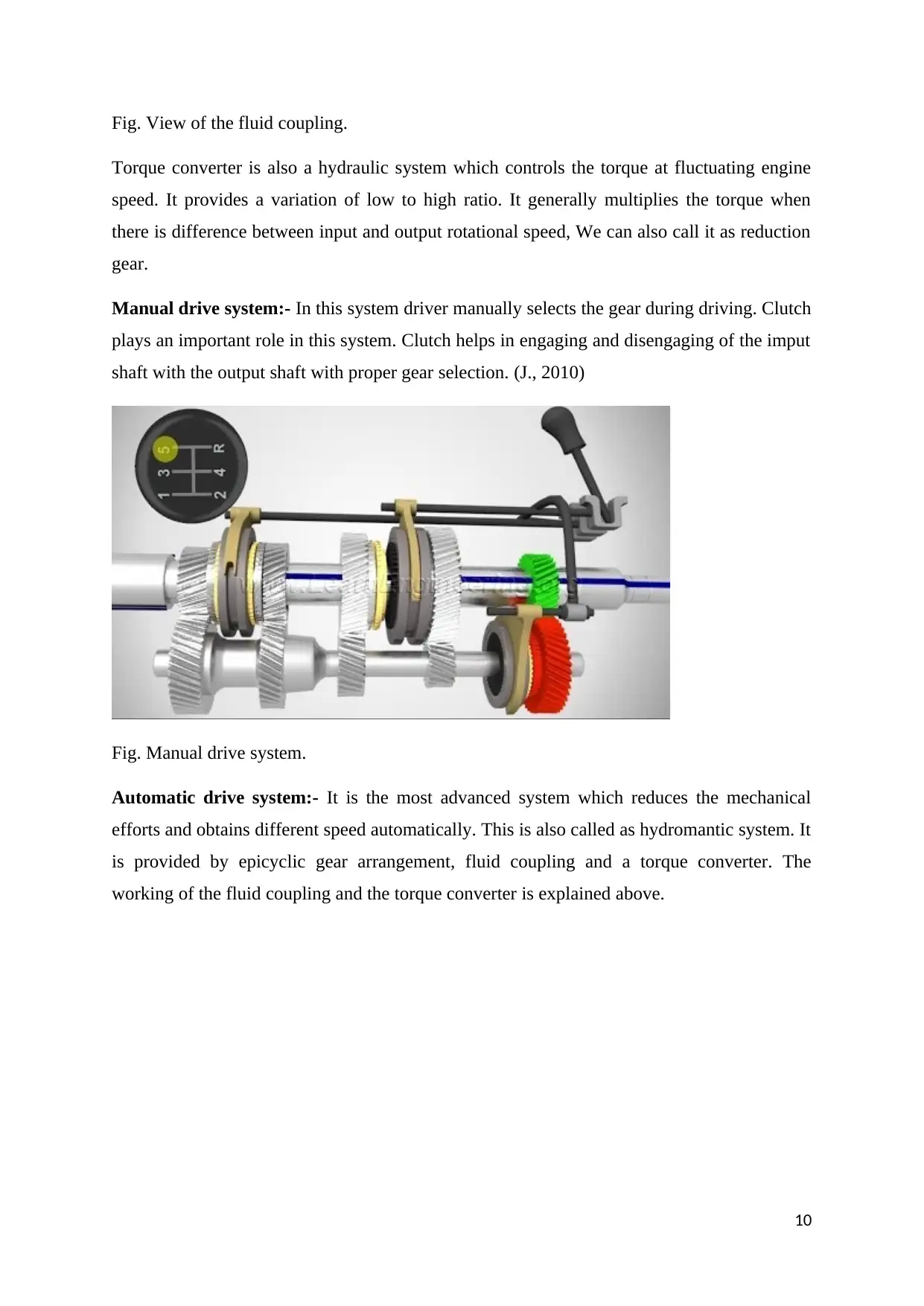
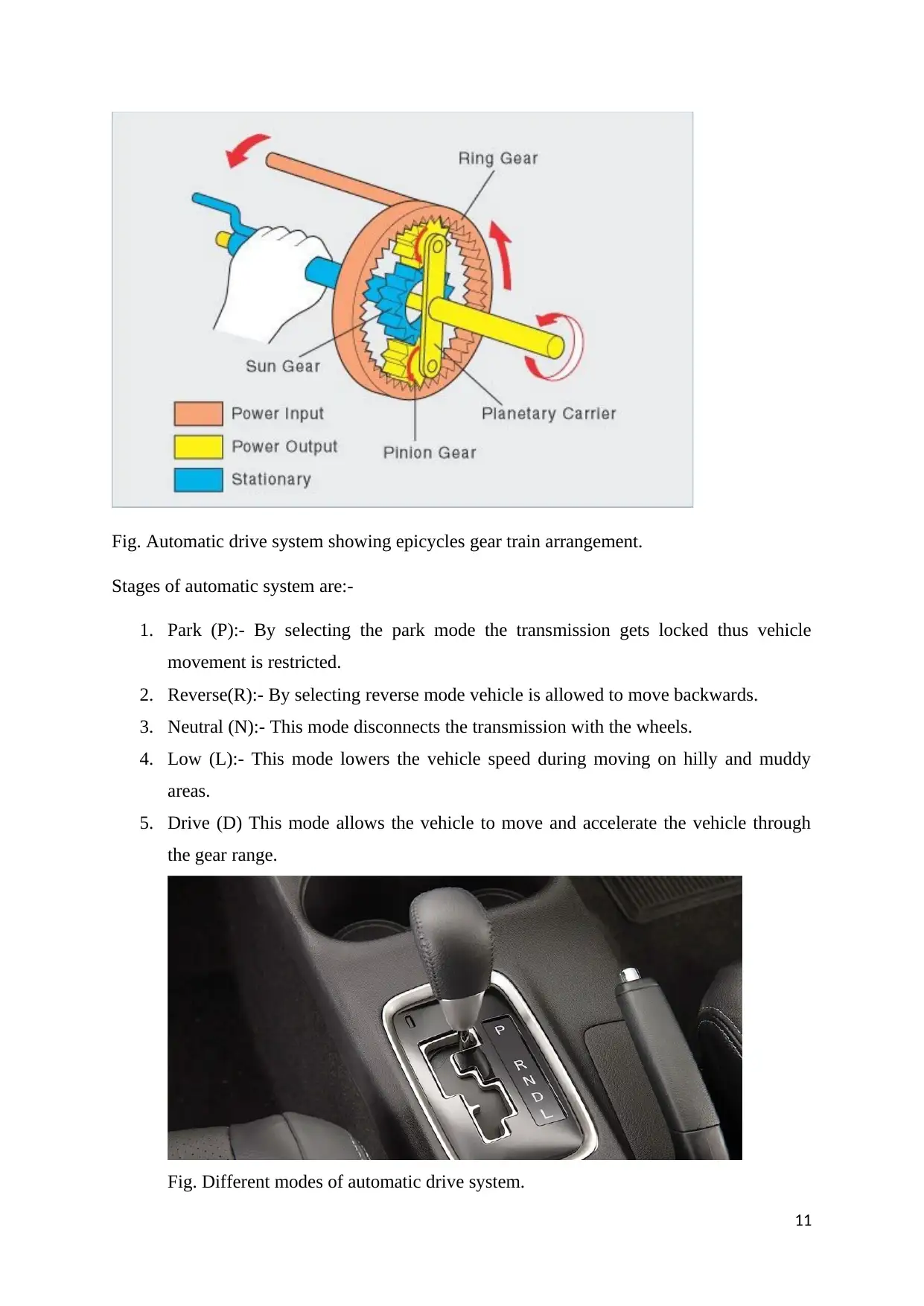
This report provides a comprehensive analysis of a diesel train drive system, focusing on the selection and layout design of suitable transmission systems for a new generation of diesel trains with underfloor diesel engines. It covers various aspects, including automotive-type transmissions, component torque and speed considerations, locomotive layout, main gearbox ratio selection, tractive effort calculations, and acceleration analysis. The report also explores alternative drive systems, such as hydraulic, manual, and automatic systems, highlighting their features and applications in diesel train technology. The analysis includes plots of speed vs. distance and residual force vs. acceleration, based on assumed values, with recommendations for practical result validation. This document is available on Desklib, a platform offering a range of study tools and resources for students.

DIESEL TRAIN DRIVE SYSTEM ASSIGNMENT
[Document subtitle]
[DATE]
[Company name]
[Company address]
[Document subtitle]
[DATE]
[Company name]
[Company address]
Paraphrase This Document
Need a fresh take? Get an instant paraphrase of this document with our AI Paraphraser

Table of Content
1. Automotive Type Transmission
2. Component Torque and Speed
3. Layout of Locomotive
4. Main Gearbox ratio selection
5. Calculation of Tractive effort in each gear
6. Calculation of acceleration
7. Plot between Speed & distance
8. Requirements met & Improvements
9. The three fundamental drive systems
10. Reference
1

Automotive Type Transmission (R, et al., 2015):
Differential: The differential is a device that splits the engine torque two ways, allowing
each output to spin at a different speed. The differential is found on all modern cars and
trucks, and also in many all-wheel-drive (full-time four-wheel-drive) vehicles. Differential
helps in turning the drive wheels at different rpm while the vehicle takes a turn Differential
gear, in automotive mechanics, gear arrangement that permits power from the engine to be
transmitted to a pair of driving wheels, dividing the force equally between them but
permitting them to follow paths of different lengths, as when turning a corner or traversing an
uneven road. Wheels receive power from the engine via a drive shaft. The wheels that receive
power and make the vehicle move forward are called the drive wheels. The main function of
the differential gear is to allow the drive wheels to turn at different rpms while both receiving
power from the engine. When a large vehicle has to curve on road, outer wheels cover more
distance as compared to inner wheels, so in order that wheels do not skid, we use Differential.
It consists of no. of gear wheels like Crown Wheel or Ring Gear and Tail Pinion. Tail pinion
is mounted after propeller shaft. It drives Ring Gear which consists of Sun and planet gear
assembly. So whatever the type of curve is, Lift or Right Turn, that respective shaft, precisely
2
Vehicle
Power Plant
Clutch Gear box Differential
Driven Wheal
Drive Shaft
Drive Shaft
Driven WhealDriven Wheal
G1150 Gearbox
⊘ This is a preview!⊘
Do you want full access?
Subscribe today to unlock all pages.

Trusted by 1+ million students worldwide

B.P. shaft, revolves faster, resulting in that wheel revolving faster. Differential can be used in
Rear or Front Axle or in both, depending on Drive, 2 wheel Front or Rear Drive or Four
wheel Drive.
Gear Box: The gear box is the second element of the power train in an automobile. It is used
to change the speed and torque of vehicle according to variety of road and load condition. A
gear box changes the engine speed into torque when climbing hills and when the vehicle
required. Sometimes it is known as torque converter. Provide the torque needed to move the
vehicle under a variety of road and load conditions. It does this by changing the gear ratio
between the engine crankshaft and vehicle drive wheels. Gearboxes are nothing but gear
trains mainly for power transmission from the power producing device to the vehicle's
wheels, reducing torque increasing speed, and maintaining the speed and torque of the
machine shaft and transmission shaft. The gearbox is a set of gears packed into a casing. The
gears inside are of different sizes and have different number of teeth. This is because, the
gearbox can then cater to the demand of varying speed and torque. Each gear has a specific
speed and torque response. It is combination or a set of gears meshing each other & mounted
on shafts with bearing to support them. It can be used either to reduce or increase the speed
ratio of input shaft. The housing will have usually two halves bolted to each other & uses a
lubricating oil filled inside to reduce heat due to friction caused by meshing of gears. This is a
general concept of gear box basically to transmit power or rotation from one drive to another.
Clutch: A clutch is a mechanical device which engages and disengages power transmission
especially from driving shaft to drive shaft. The principle behind working of clutches
(friction) is that no torque/power gets transmitted until both the friction plates touch each
other. One friction plate is bolted to flywheel & the other is movable over the crankshaft. Its
function is to transmit the torque from the engine to the drivetrain, smoothly deliver the
power from the engine to enable smooth vehicle movement, Perform quietly and to reduce
drive-related vibration. The clutch connects the engine to the wheels and when we step on
3
Paraphrase This Document
Need a fresh take? Get an instant paraphrase of this document with our AI Paraphraser

the clutch it disconnects the engine. Clutch control refers to the act of controlling the speed
of a vehicle with a manual transmission by partially engaging the clutch plate, using the
clutch pedal instead of (or in conjunction with) the accelerator pedal. Clutch works on the
principle of friction because when the two rough surface clutch plates are comes in contact
with each other then they become rotating as a single unit. In the simplest application
clutches are employed in devices which have two rotating shafts. In these devices one shaft is
typically attached to a motor or other power unit (the driving member) while the other shaft
(the driven member) provides output power for work to be done. Some types of clutches used
in vehicles are given below : (a) Friction Clutch : It may be (i) single plate clutch, (ii) multi-
plate clutch, or (iii) cone clutch.
Requirements of Clutch System:
1. It pick up its load smoothly without grab or clatter
2. It damp out any vibration of the crankshaft to prevent gear clatter
3. Require little pedal pressure to operate it.
4. Easy to adjust and service
5. Be cheap to manufacture
6.2 Component Torque and Speed:
Considering vehicle Power plant as a diesel engine
Let Efficiency of diesel engine = ηd
Input Power = Indicated Power = Brake Power + Friction Power
Pinput = Tinput x ω
Let velocity of Piston = 2LN = Vp
Where N= rpm
N= Speed (rpm)
N= n for 2 stroke
N= n/2 for 4 stroke
N= rpm i.e revolution of crank per min.
Pinput= Indicated Power (IP)
4

ω= 2πn/60
Considering 2 stroke engine
N= Vp/2L
L = length of stroke
Pinput = Tinput x ω = Ip
Tinput= IP/ ω = Input Torque.
Let ηmech= Mechanical Efficiency of Engine
Toutput= Brake Power/ω = IP X ηmech/ω (W. & P., 2004)
For Under Floor Rail engine We consider Locomotive of 4500 hp two stroke diesel engine
5
Considering 2 stroke engine
N= Vp/2L
L = length of stroke
Pinput = Tinput x ω = Ip
Tinput= IP/ ω = Input Torque.
Let ηmech= Mechanical Efficiency of Engine
Toutput= Brake Power/ω = IP X ηmech/ω (W. & P., 2004)
For Under Floor Rail engine We consider Locomotive of 4500 hp two stroke diesel engine
5
⊘ This is a preview!⊘
Do you want full access?
Subscribe today to unlock all pages.

Trusted by 1+ million students worldwide

6.3 Layout of Locomotive:
6.4 Main Gearbox ratio selection
In diesel locomotive the gears are only used in between the traction motor & the wheal by
Gear pinion arrangements
The Gear ratio the above system is
Calculating by following law of gearing concept
i.e ωp/ ωg = T/t = Gear ratio
t= no. of teeth on driver/ gear
T = no. of teeth on driven/ pinion
Now, Power of Pinion = ηgear X Power at gear
Power at gear = ηmotor X Electrical power
ωp = angular speed of pinion (rad s-1)
ωg = angular speed of pinion (rad s-1)
6
Diesel Engine Gearbox
Wheals
Traction
Alternator
Internal
Rectifier bank
Inverters
Traction
Inverter 1
Gear Transmission
4 Induction
Tractor motor
3 Induction
Tractor motor
Traction
Inverter 2
Traction motors
Are parallelly arranged
Gear & Pinion
Arrangement
Paraphrase This Document
Need a fresh take? Get an instant paraphrase of this document with our AI Paraphraser

Power = Torque X angular Speed (B., et al., 2011)
6.5 Calculation of Tractive effort in each gear
Tractive effort on the Driven Wheal is given by
Ft = Tω / rdyn
Tω = Torque Transferred to the driven wheals
rdyn= Dynamic radius of the type
For Driven gear, tractive effort is given by
Ft = Tp / rp
Tp= Torque Transferred to pinion
Rp= Dynamic radius of the Pinion
Vehicle speed can be given be
V =π Nprdyn / 30G
G = Gear ratio
rdyn = Dynamic radius of Wheal
Np = Speed of Pinion (rpm)
6.6. Calculation of acceleration:-
S=(u*t)+(0.5a*t^2)
Where,
S= distance travelled.
u= initial velocity =0
v= final velocity
t= time taken.
7

Therefore, acceleration a= (2*S)/(t^2)
Residual force = Mass of vehicle * Acceleration
6.7. A) Plot between Speed & distance
0 5 10 15 20 25
0
5
10
15
20
25
30
distance vs speed
distance vs speed
B) Plot between Residual force & acceleration
0 2000 4000 6000 8000 10000
0
0.05
0.1
0.15
0.2
0.25
0.3
residual force vs accelration
residual force vs
accelration
8
⊘ This is a preview!⊘
Do you want full access?
Subscribe today to unlock all pages.

Trusted by 1+ million students worldwide

6.8. The above transmission system is totally based on the assumption values. To check the
practical result the practical values can be used in the expressions and the results can be
evaluated.
6.9. The three fundamental drive systems are:-
1. Hydraulic drive system.
2. Manual drive system
3. Automatic drive system.
Hydraulic drive system: - Basically this system comprises of fluid coupling and the torque
converter.
A fluid coupling is a hydraulic system which transmits rotating mechanical power. In other
words we call it as a hydrodynamic system. It is an alternative to the mechanical clutch. The
turbine is connected to the input shaft of the automobile engine. As the speed of engine
increases the torque is transferred to the input shaft by the motion of the fluid (Galal, 2009).
9
Paraphrase This Document
Need a fresh take? Get an instant paraphrase of this document with our AI Paraphraser

Fig. View of the fluid coupling.
Torque converter is also a hydraulic system which controls the torque at fluctuating engine
speed. It provides a variation of low to high ratio. It generally multiplies the torque when
there is difference between input and output rotational speed, We can also call it as reduction
gear.
Manual drive system:- In this system driver manually selects the gear during driving. Clutch
plays an important role in this system. Clutch helps in engaging and disengaging of the imput
shaft with the output shaft with proper gear selection. (J., 2010)
Fig. Manual drive system.
Automatic drive system:- It is the most advanced system which reduces the mechanical
efforts and obtains different speed automatically. This is also called as hydromantic system. It
is provided by epicyclic gear arrangement, fluid coupling and a torque converter. The
working of the fluid coupling and the torque converter is explained above.
10

Fig. Automatic drive system showing epicycles gear train arrangement.
Stages of automatic system are:-
1. Park (P):- By selecting the park mode the transmission gets locked thus vehicle
movement is restricted.
2. Reverse(R):- By selecting reverse mode vehicle is allowed to move backwards.
3. Neutral (N):- This mode disconnects the transmission with the wheels.
4. Low (L):- This mode lowers the vehicle speed during moving on hilly and muddy
areas.
5. Drive (D) This mode allows the vehicle to move and accelerate the vehicle through
the gear range.
Fig. Different modes of automatic drive system.
11
⊘ This is a preview!⊘
Do you want full access?
Subscribe today to unlock all pages.

Trusted by 1+ million students worldwide
1 out of 15
Related Documents

Your All-in-One AI-Powered Toolkit for Academic Success.
+13062052269
info@desklib.com
Available 24*7 on WhatsApp / Email
Unlock your academic potential
Copyright © 2020–2025 A2Z Services. All Rights Reserved. Developed and managed by ZUCOL.