Teesside University DADC Module: Digital Devices & Circuits TMA 3
VerifiedAdded on 2023/04/22
|16
|2255
|467
Homework Assignment
AI Summary
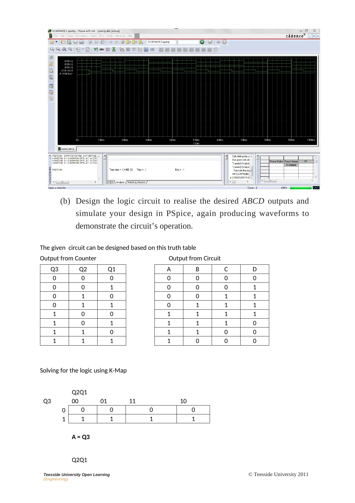
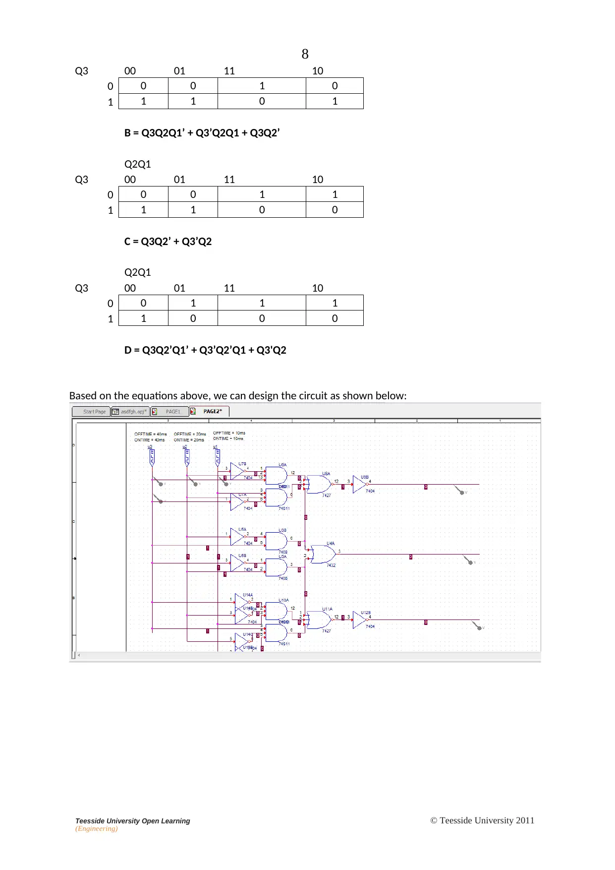
This document presents a comprehensive solution to a Tutor Marked Assignment (TMA 3) for a Digital & Analogue Devices & Circuits module. The assignment covers several key areas within digital electronics, including the analysis of an ALS logic circuit, estimation of current, propagation delay, and power consumption. It delves into the concept of noise immunity, explaining its significance with sketches and examples of logic families. The solution also addresses the problems associated with interfacing different logic families, such as TTL and CMOS, providing remedies like pull-up resistors. Furthermore, the assignment involves the design and simulation of an asynchronous counter using D flip-flops, with PSpice simulations demonstrating its operation. The design of a logic circuit to generate specific outputs from the counter is also included, along with the corresponding PSpice simulations. The document concludes with a comparison of various logic families, detailing their performance specifications.

MODULE TITLE : DIGITAL & ANALOGUE DEVICES & CIRCUITS
TOPIC TITLE : DIGITAL DEVICES & CIRCUITS
TUTOR MARKED ASSIGNMENT 3 (v1.1)
NAME........................................................................................................................................
ADDRESS .................................................................................................................................
...................................................................................................................................................
...................................................................................................................................................
...................................................... HOME TELEPHONE .....................................................
EMPLOYER..............................................................................................................................
...................................................................................................................................................
...................................................................................................................................................
...................................................... WORK TELEPHONE......................................................
Student declaration:
I declare that all the work submitted is my own work and that no part of it has been copied from
any other source without full acknowledgement and complies with the University's guiding
principles as stated in the Regulations Relating To Academic Misconduct*.
Student signature:.....................................................................................................
Date: ....................................................................................................
Student code: ....................................................................................................
Email: ....................................................................................................
*http://www.tees.ac.uk/docs/index.cfm?folder=Student%20Regulations&name=Academic%20Regulations
DADC - 3 - TMA (v1.1)
© Teesside University 2011
Paraphrase This Document
Need a fresh take? Get an instant paraphrase of this document with our AI Paraphraser

Published by Teesside University Open Learning (Engineering)
School of Science & Engineering
Teesside University
Tees Valley, UK
TS1 3BA
+44 (0)1642 342740
All rights reserved. No part of this publication may be reproduced, stored in a
retrieval system, or transmitted, in any form or by any means, electronic, mechanical,
photocopying, recording or otherwise without the prior permission
of the Copyright owner.
This book is sold subject to the condition that it shall not, by way of trade or
otherwise, be lent, re-sold, hired out or otherwise circulated without the publisher's
prior consent in any form of binding or cover other than that in which it is
published and without a similar condition including this
condition being imposed on the subsequent purchaser.

Teesside University Open Learning
(Engineering)
© Teesside University 2011
1
IMPORTANT
Before you start please read the following instructions carefully.
1. This assignment forms part of the formal assessment for this module. If
you fail to reach the required standard for the assignment then you will be
allowed to resubmit but a resubmission will only be eligible for a Pass
grade, not a Merit or Distinction.
You should therefore not submit the assignment until you are reasonably
sure that you have completed it successfully. Seek your tutor's advice if
unsure.
2. Ensure that you indicate the number of the question you are answering.
3. Make a copy of your answers before submitting the assignment.
4. Complete all details on the front page of this TMA and return it with
the completed assignment including supporting calculations where
appropriate. The preferred submission is via your TUOL(E) Blackboard
account:
https://eat.tees.ac.uk
5. Your tutor’s comments on the assignment will be posted on Blackboard.
⊘ This is a preview!⊘
Do you want full access?
Subscribe today to unlock all pages.

Trusted by 1+ million students worldwide

2
Teesside University Open Learning
(Engineering)
© Teesside University 2011
Assessment Criteria
This assignment takes the form of a design exercise to an engineering problem
concerning a digital system. The assignment forms Element 3 of the module’s
assessment criteria that covers in part Learning Outcomes 1, 2, 3 and 4 as
indicated below.
MODULE LEARNING OUTCOMES
Knowledge and Understanding
1. Demonstrate an understanding of a variety of electronic circuits including
power supplies, operational amplifier circuits and digital logic circuits.
Cognitive and Intellectual Skills
2. Choose appropriate circuit components for the design of electronic circuits.
Practical and Professional Skills
3. Build, simulate and test simple electronic circuits.
Key Transferable Skills
4. Demonstrate the application of numerical skills to the solution of problems
relating to digital and analogue devices and circuits.
PASS MERIT
Criteria in excess of the pass
grade.
DISTINCTION
Criteria in excess of the
merit grade.
Learning outcomes are
satisfied as evidenced by
substantially correct
understanding of the
operation and application of
simple operational amplifier
circuits.
The transfer of competence
gained in one situation to
related but unfamiliar
circumstances.
The ability to integrate
knowledge from two or
more topic areas to solve a
significantly more complex
problem.
Paraphrase This Document
Need a fresh take? Get an instant paraphrase of this document with our AI Paraphraser

3
Teesside University Open Learning
(Engineering)
© Teesside University 2011
Refer to the tables at the end of the TMA when answering Questions 1 and 2.
1. FIGURE 1 shows an ALS logic circuit. Estimate:
(a) the current IOL
0.4mA as Output from gate. According to INTERFACING LOGIC
FAMILIES Table mentioned in the end of the document
(b) the delay in a 1-to-0 transition at one of the inputs of GATE 1
appearing as an effect at the output of GATE 5.
Propagation delay of one single gate is 4ns. For change in input at
GATE 1 to reflect on output at GATE 5, needs three propagation
delays. So total time is 12ns.
(c) the total power consumed by the circuit in a quiescent state.
Each gate has power consumption of 1mW. Total of 5 GATES will
consume 5mW of power.
2
1
IOL
1 11 4
1 5
1
3
1
FIG. 1

4
Teesside University Open Learning
(Engineering)
© Teesside University 2011
2. (a) Explain with the aid of sketches and by using an example of a
specific logic family, what is meant by the term ‘noise immunity’.
The signals in gates are propagated and acknowledged based on their
Voltage levels. There is limit where a certain Maximum Voltage is
counted as 0 beyond which it would not be taken as 0 signal.
Similarly there is a minimum Voltage that must appear at input to be
counted as 1. Any Voltage below that level will not get counted as 1.
(05_digital_circuitry.pdf)
The outputs from a gate must confirm to these voltage levels.
However there might be some slight change in actual voltage levels
that appear of input of next Gate. The amount of Voltage fluctuation
that can be handled by a circuit in these expected voltage levels is
called noise immunity of that circuit or Gate.
Like in Diagram the Blue area is the indicator of noise immunity of
the circuit.
(b) Explain, if any, the problems associated with interfacing the logic
families of the circuits of FIGURE 2(a) and of FIGURE 2(b). For
each circuit, if there is a problem of interfacing, give a remedy.
⊘ This is a preview!⊘
Do you want full access?
Subscribe today to unlock all pages.

Trusted by 1+ million students worldwide

5
Teesside University Open Learning
(Engineering)
© Teesside University 2011
+5 V +5 V
7404 TTL
(a)
4049B CMOS
Interfacing of TTL to CMOS needs following 4 conditions to be satisfied:
VOH (TTL) ≥ VIH(CMOS)
VOL (TTL) ≤ VIL(CMOS)
-IOH (TTL) ≥ IIH(CMOS)
IOL (TTL) ≥ -IIL(CMOS)
The Current levels given in the datasheet confirm the required current conditions are met
when interfacing two families. The Two voltage conditions are however not satisfied. Only
the Low voltage levels are satisfied. The Output High Voltage of the TTL is far less than the
required Minimum voltage. To get the TTL drive a CMOS, a pull up resistor is required that
allows CMOS input to connect to supply voltage. The pull up resistance should be such that
Sink Current in TTL when input is low is within limits of TTL logic.
+5 V +5 V
4049B CMOS 7404 TTL
(b)
When interfacing the CMOS to a TTL circuit, the following 4 conditions need to be satisfied:
VOH (CMOS) ≥ VIH(TTL) 4.95 > 2.0
VOL (CMOS) ≤ VIL(TTL) .05 < 0.8
– IOH (CMOS) ≥ IIH(TTL) 0.51mA > 40uA
IOL (CMOS) < – IIL(TTL) 0.51mA < 1.6mA
Given data in the datasheet, confirms the ability of CMOS driver to provide sufficient Voltage levels to
count as logic 1 or 0 at the input of TTL device. Both limits are well within range of the required
values. The Current requirements of the driver also needs to be considered in this case. The current
for logic 1 is sufficiently large current for logic 0 is also well beyond maximum value allowed by TTL. So
device can connect directly without any other component.
Paraphrase This Document
Need a fresh take? Get an instant paraphrase of this document with our AI Paraphraser

6
Teesside University Open Learning
(Engineering)
© Teesside University 2011
3. The block diagram of FIGURE 3 shows a three-stage asynchrononous
counter that is used to count a series of randomly occurring input pulses.
The ‘Q’ outputs of the counter are used to drive a logic circuit that gives
the output shown in TABLE 1.
(a) Design the counter using type D flip-flops and simulate your design
in PSpice, producing waveforms to confirm the circuit’s operation.
The circuit is an asynchronous UP counter using 3 D flip flops.
Initially a logic 0 is applied to the PRE pins of the flops. This resets
all flip flops. Then Inverted output of each flip flop is connected to
the input of the same flip flop. This helps toggle the flip flop in each
input clock. The asynchronous impulse input is used as clock to drive
the D flip flop. Output of the First stage is used as input clock for the
second clock. This makes a 3 bit asynchronous counter. The results
are available as Q1, Q2 and Q3. The same is visible in waveform
shown below.

7
Teesside University Open Learning
(Engineering)
© Teesside University 2011
(b) Design the logic circuit to realise the desired ABCD outputs and
simulate your design in PSpice, again producing waveforms to
demonstrate the circuit’s operation.
The given circuit can be designed based on this truth table
Output from Counter Output from Circuit
Q3 Q2 Q1 A B C D
0 0 0 0 0 0 0
0 0 1 0 0 0 1
0 1 0 0 0 1 1
0 1 1 0 1 1 1
1 0 0 1 1 1 1
1 0 1 1 1 1 0
1 1 0 1 1 0 0
1 1 1 1 0 0 0
Solving for the logic using K-Map
Q2Q1
Q3 00 01 11 10
0 0 0 0 0
1 1 1 1 1
A = Q3
Q2Q1
⊘ This is a preview!⊘
Do you want full access?
Subscribe today to unlock all pages.

Trusted by 1+ million students worldwide

8
Teesside University Open Learning
(Engineering)
© Teesside University 2011
Q3 00 01 11 10
0 0 0 1 0
1 1 1 0 1
B = Q3Q2Q1’ + Q3’Q2Q1 + Q3Q2’
Q2Q1
Q3 00 01 11 10
0 0 0 1 1
1 1 1 0 0
C = Q3Q2’ + Q3’Q2
Q2Q1
Q3 00 01 11 10
0 0 1 1 1
1 1 0 0 0
D = Q3Q2’Q1’ + Q3’Q2’Q1 + Q3'Q2
Based on the equations above, we can design the circuit as shown below:
Paraphrase This Document
Need a fresh take? Get an instant paraphrase of this document with our AI Paraphraser

9
Teesside University Open Learning
(Engineering)
© Teesside University 2011
Teesside University Open Learning
(Engineering)
© Teesside University 2011

Logic
1
0
Teesside University Open Learning
(Engineering)
© Teesside University 2011
In
Counter
t
Q1 Q2 Q3
A B C D
FIG. 3
Input pulse D C B A
0 0 0 0 0
1 0 0 0 1
2 0 0 1 1
3 0 1 1 1
4 1 1 1 1
5 1 1 1 0
6 1 1 0 0
7 1 0 0 0
8 0 0 0 0
9 0 0 0 1
etc
TABLE 1
1
0
Teesside University Open Learning
(Engineering)
© Teesside University 2011
In
Counter
t
Q1 Q2 Q3
A B C D
FIG. 3
Input pulse D C B A
0 0 0 0 0
1 0 0 0 1
2 0 0 1 1
3 0 1 1 1
4 1 1 1 1
5 1 1 1 0
6 1 1 0 0
7 1 0 0 0
8 0 0 0 0
9 0 0 0 1
etc
TABLE 1
⊘ This is a preview!⊘
Do you want full access?
Subscribe today to unlock all pages.

Trusted by 1+ million students worldwide
1 out of 16
Related Documents

Your All-in-One AI-Powered Toolkit for Academic Success.
+13062052269
info@desklib.com
Available 24*7 on WhatsApp / Email
Unlock your academic potential
Copyright © 2020–2025 A2Z Services. All Rights Reserved. Developed and managed by ZUCOL.