Solved Assignment: Digital Logic Circuits and Design with Multisim

Verified

Added on  2023/04/22

|8
|598
|290
Homework Assignment
AI Summary
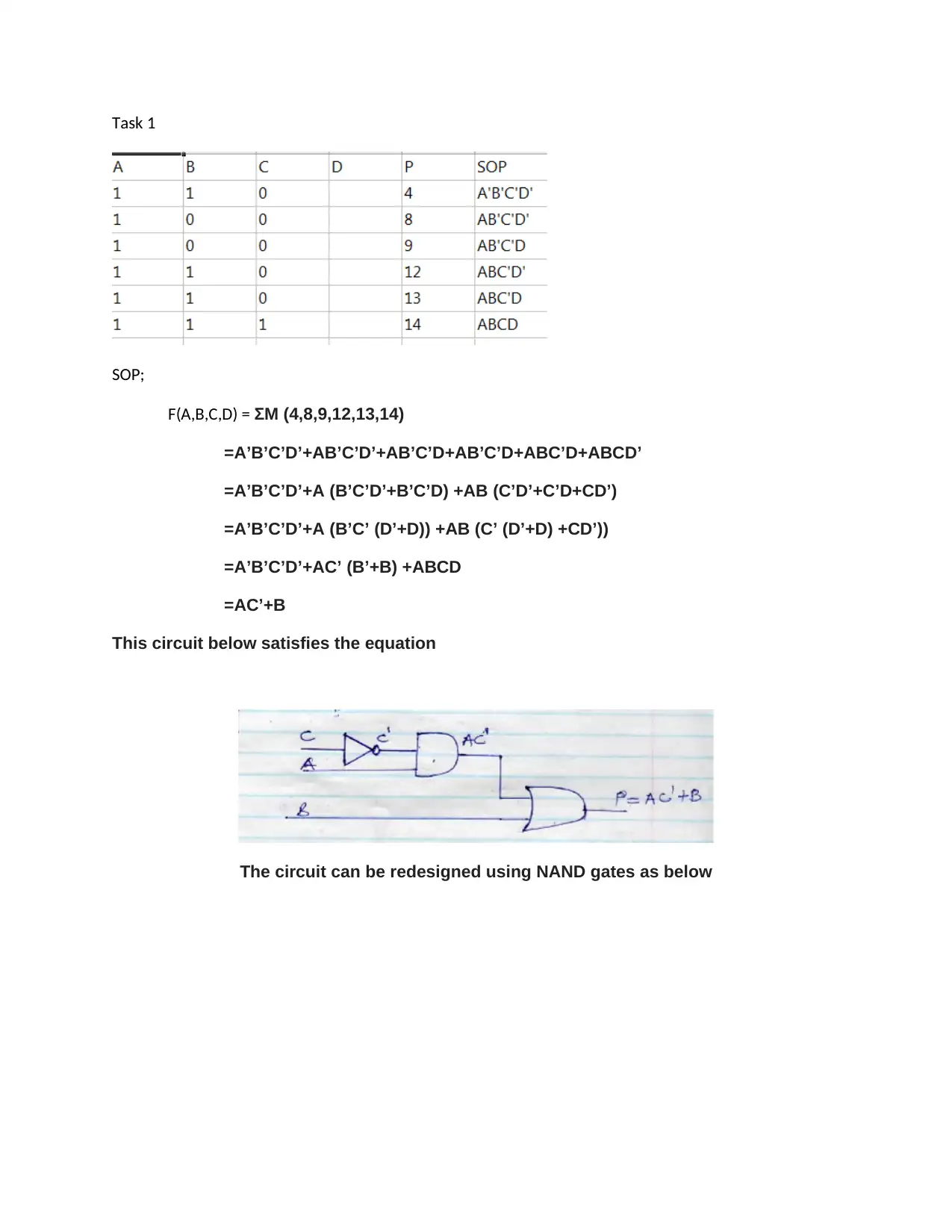
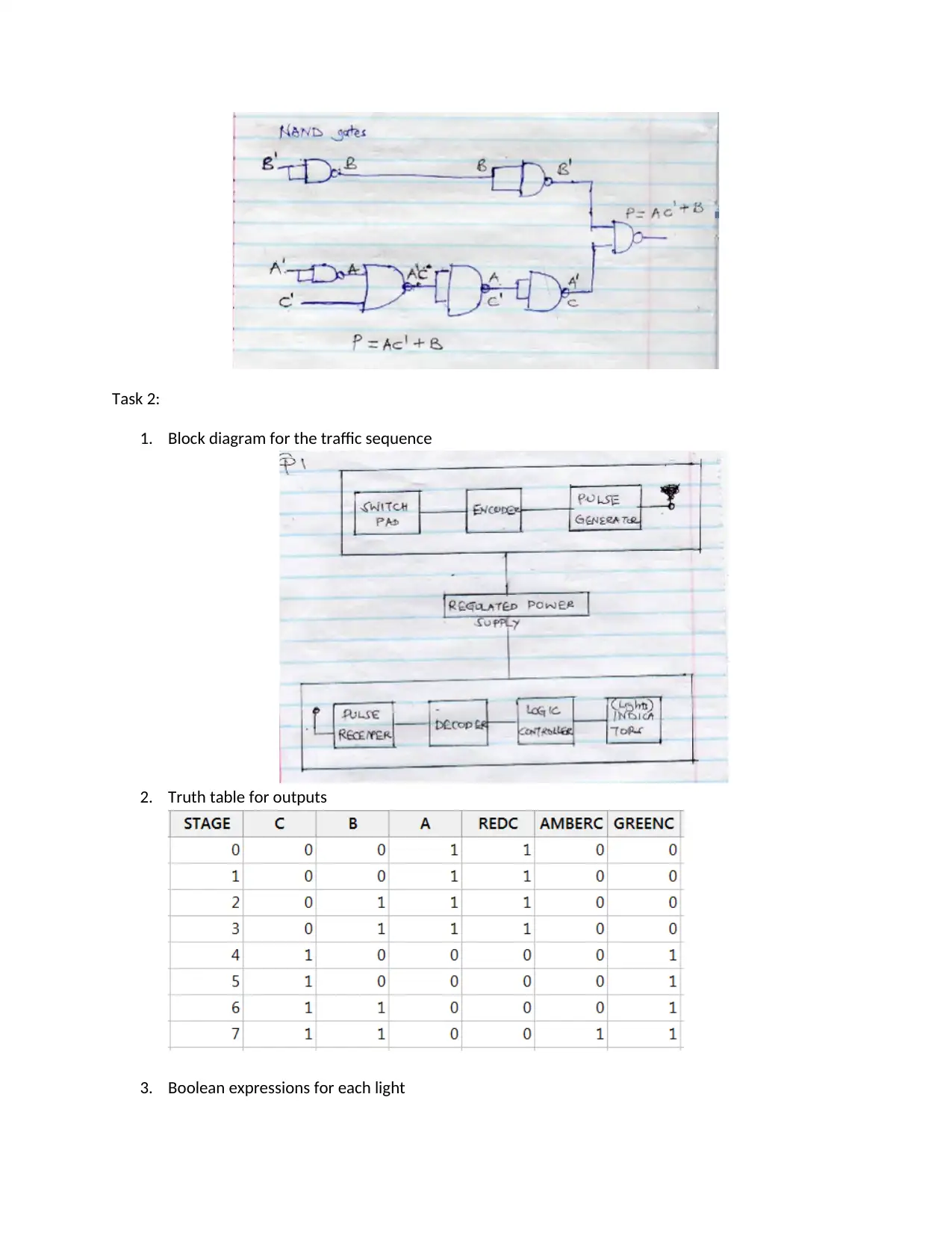
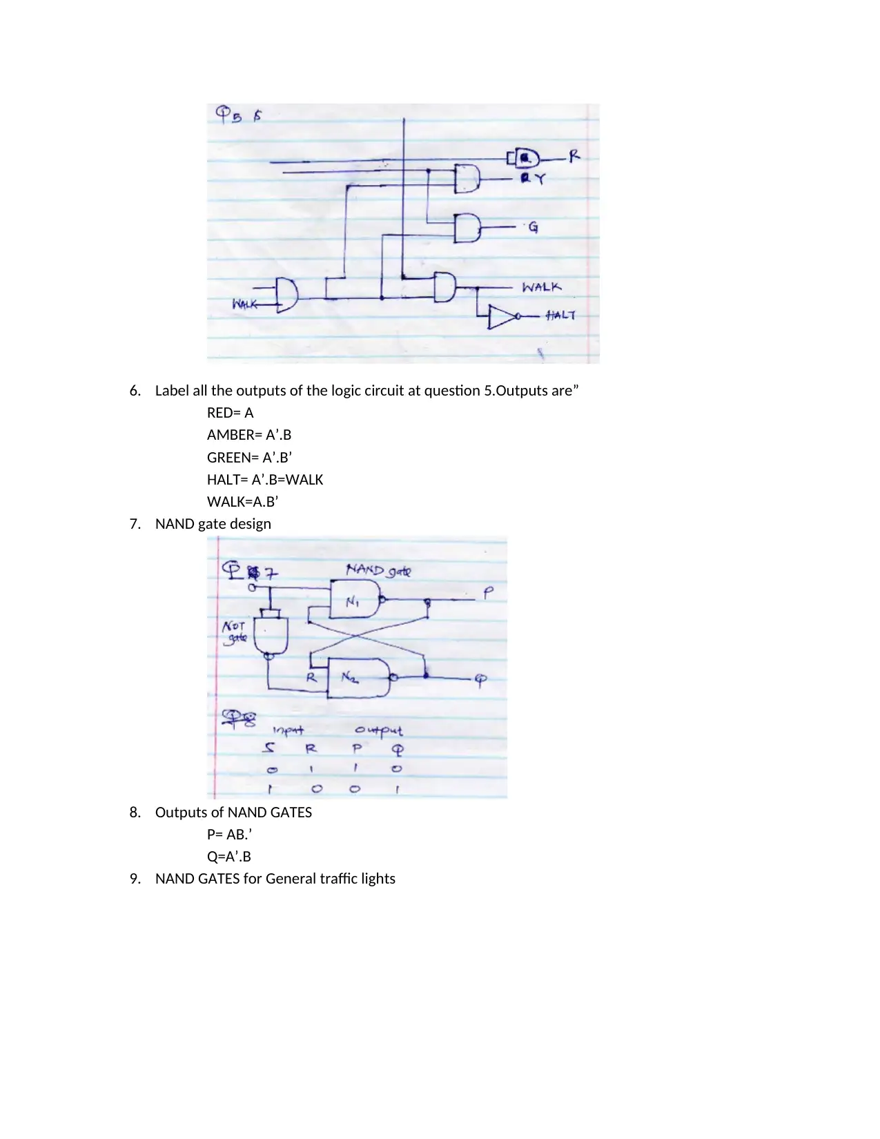
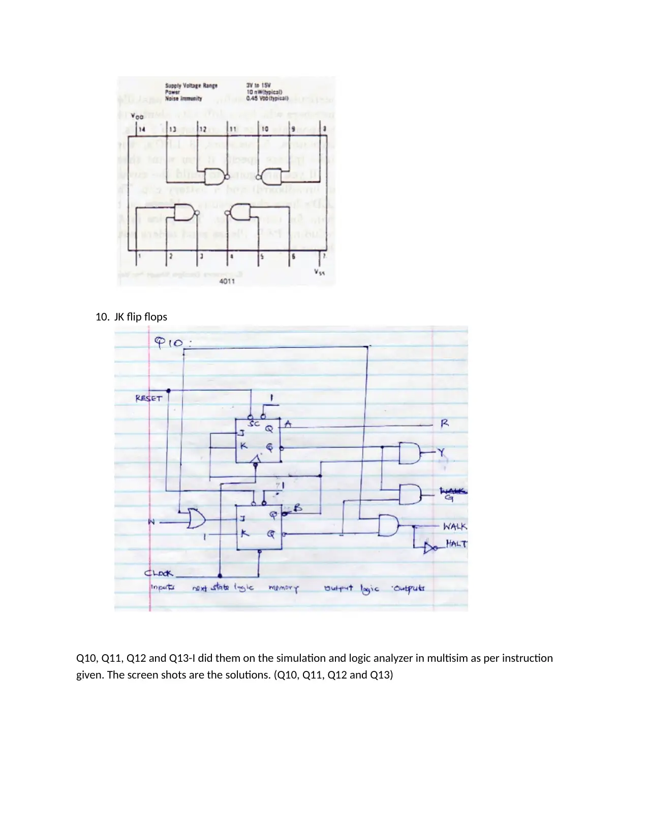
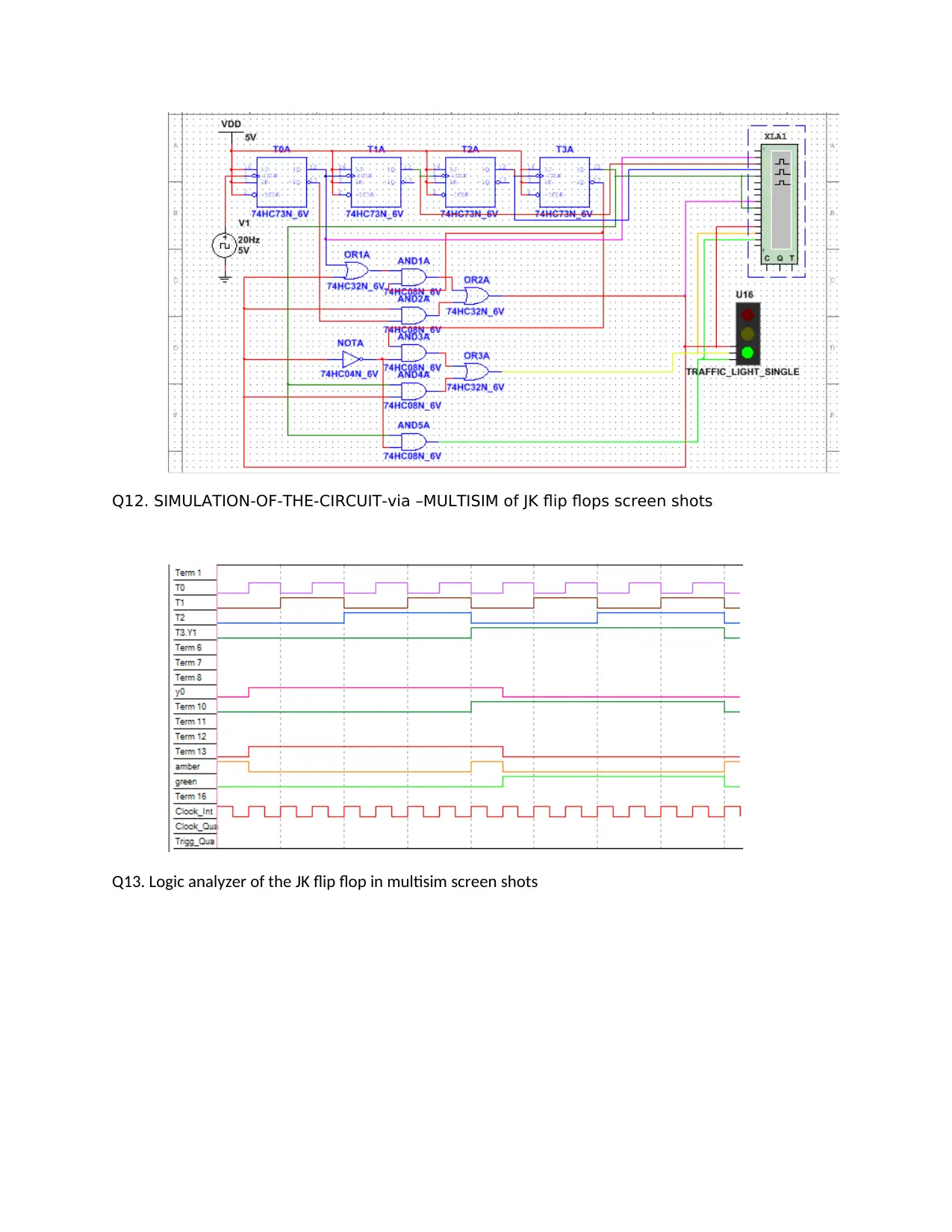
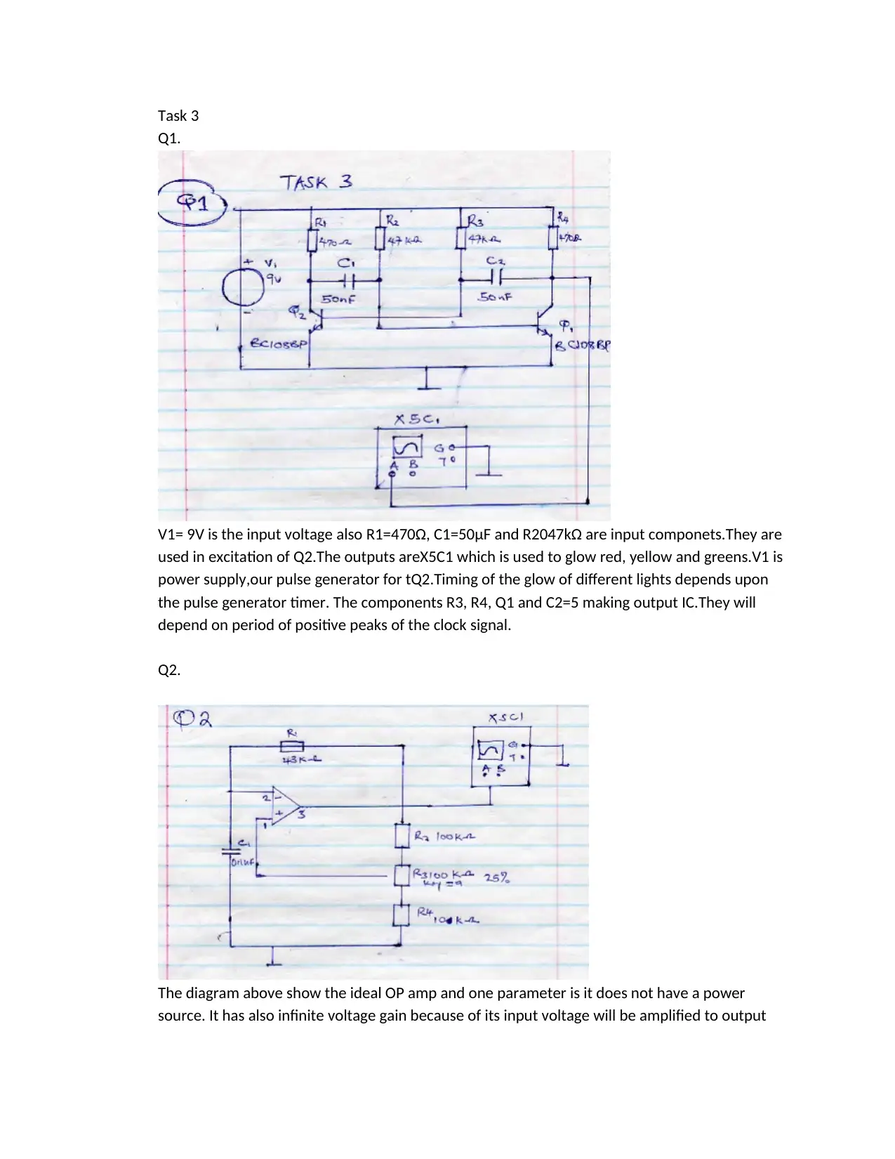
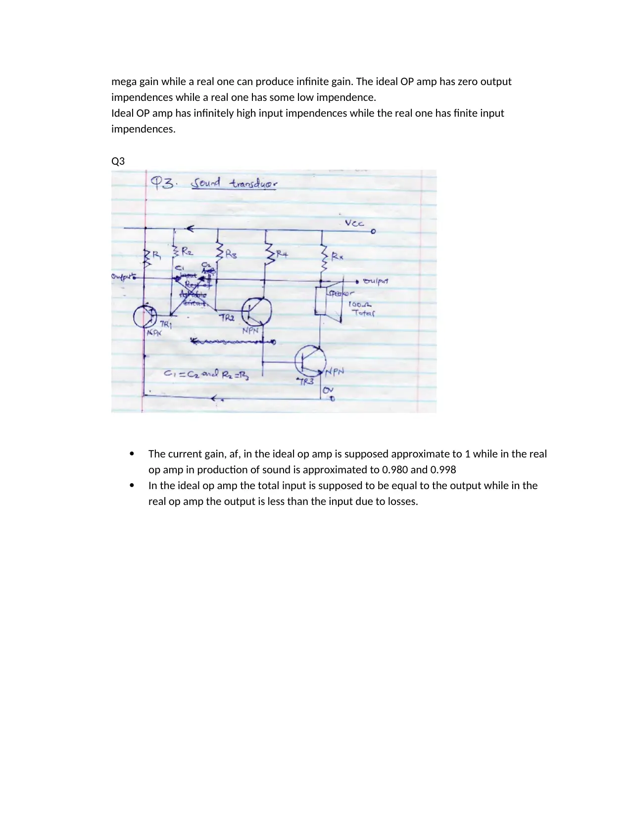
This document presents a detailed solution to a Digital Logic Circuits and Design assignment, covering various aspects of digital circuit design and analysis. Task 1 focuses on simplifying a Boolean function using the Sum of Products (SOP) method and implementing the resulting circuit using both basic gates and NAND gates. Task 2 involves designing a traffic light controller, including developing a block diagram, truth table, Boolean expressions, and K-Map minimization, culminating in a circuit design using AND, OR, and NOT gates, as well as NAND gates, with JK flip flops simulated in Multisim. Task 3 explores operational amplifier (op-amp) characteristics, comparing ideal and real op-amps and analyzing a circuit with specific component values, including voltage, resistance, and capacitance, to understand its functionality. The assignment utilizes Multisim for simulation and analysis, providing practical insights into digital logic circuit design.
tabler-icon-diamond-filled.svg

Contribute Materials

Your contribution can guide someone’s learning journey. Share your documents today.
Document Page
Task 1
SOP;
F(A,B,C,D) = ΣM (4,8,9,12,13,14)
=A’B’C’D’+AB’C’D’+AB’C’D+AB’C’D+ABC’D+ABCD’
=A’B’C’D’+A (B’C’D’+B’C’D) +AB (C’D’+C’D+CD’)
=A’B’C’D’+A (B’C’ (D’+D)) +AB (C’ (D’+D) +CD’))
=A’B’C’D’+AC’ (B’+B) +ABCD
=AC’+B
This circuit below satisfies the equation
The circuit can be redesigned using NAND gates as below
tabler-icon-diamond-filled.svg

Secure Best Marks with AI Grader

Need help grading? Try our AI Grader for instant feedback on your assignments.
Document Page
Task 2:
1. Block diagram for the traffic sequence
2. Truth table for outputs
3. Boolean expressions for each light
Document Page
We can derive outputs of each lamp:
Red= ABC’D’
Amber= A’BC’D
Green = A’B’CD’
4. Using K-Maps to minimize each expression
This gives output as:
RED = A
AMBER= A’.B
GREEN=A’.B’
HALT= A’.B’= WALK
5. Use AND, OR and NOT GATES to show outputs:
Document Page
6. Label all the outputs of the logic circuit at question 5.Outputs are”
RED= A
AMBER= A’.B
GREEN= A’.B’
HALT= A’.B=WALK
WALK=A.B’
7. NAND gate design
8. Outputs of NAND GATES
P= AB.’
Q=A’.B
9. NAND GATES for General traffic lights
tabler-icon-diamond-filled.svg

Secure Best Marks with AI Grader

Need help grading? Try our AI Grader for instant feedback on your assignments.
Document Page
10. JK flip flops
Q10, Q11, Q12 and Q13-I did them on the simulation and logic analyzer in multisim as per instruction
given. The screen shots are the solutions. (Q10, Q11, Q12 and Q13)
Document Page
Q12. SIMULATION-OF-THE-CIRCUIT-via –MULTISIM of JK flip flops screen shots
Q13. Logic analyzer of the JK flip flop in multisim screen shots
Document Page
Task 3
Q1.
V1= 9V is the input voltage also R1=470Ω, C1=50μF and R2047kΩ are input componets.They are
used in excitation of Q2.The outputs areX5C1 which is used to glow red, yellow and greens.V1 is
power supply,our pulse generator for tQ2.Timing of the glow of different lights depends upon
the pulse generator timer. The components R3, R4, Q1 and C2=5 making output IC.They will
depend on period of positive peaks of the clock signal.
Q2.
The diagram above show the ideal OP amp and one parameter is it does not have a power
source. It has also infinite voltage gain because of its input voltage will be amplified to output
tabler-icon-diamond-filled.svg

Paraphrase This Document

Need a fresh take? Get an instant paraphrase of this document with our AI Paraphraser
Document Page
mega gain while a real one can produce infinite gain. The ideal OP amp has zero output
impendences while a real one has some low impendence.
Ideal OP amp has infinitely high input impendences while the real one has finite input
impendences.
Q3
The current gain, af, in the ideal op amp is supposed approximate to 1 while in the real
op amp in production of sound is approximated to 0.980 and 0.998
In the ideal op amp the total input is supposed to be equal to the output while in the
real op amp the output is less than the input due to losses.
chevron_up_icon
1 out of 8
circle_padding
hide_on_mobile
zoom_out_icon
logo.png

Your All-in-One AI-Powered Toolkit for Academic Success.

Available 24*7 on WhatsApp / Email

[object Object]