EE Project: Digital Alarm Clock Design and Implementation

Verified

Added on  2021/09/22

|4
|369
|90
Project
AI Summary
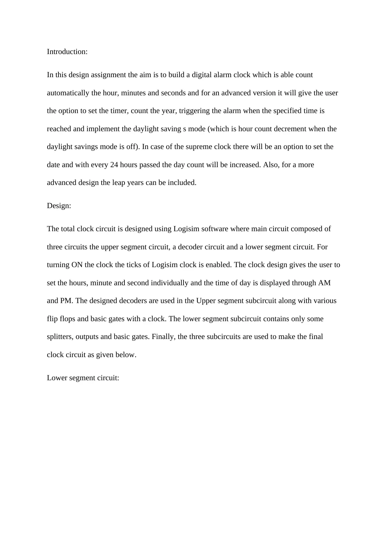
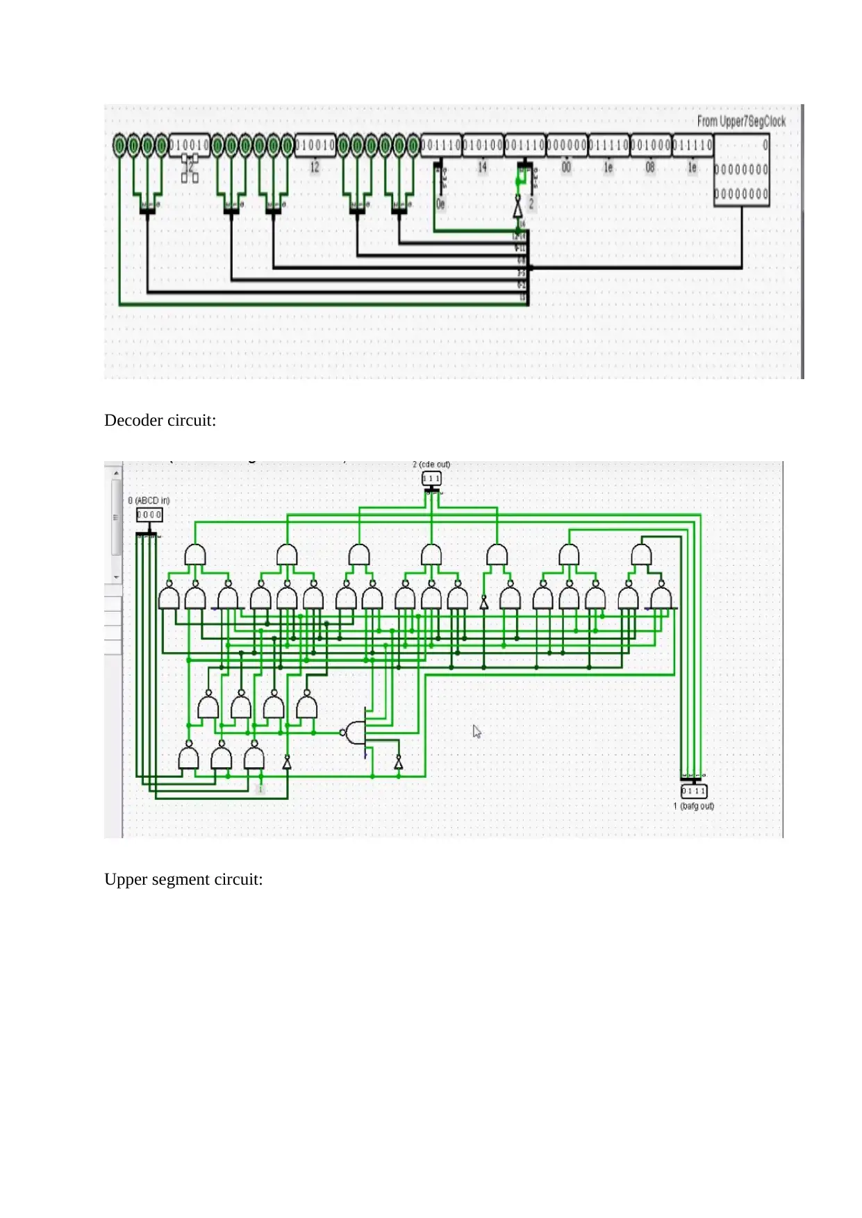
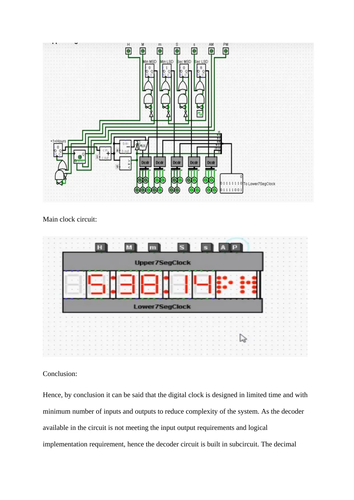
This project outlines the design of a digital alarm clock using Logisim software. The clock is designed to automatically count hours, minutes, and seconds, with advanced features including a settable timer, year count, alarm triggering, and daylight saving mode implementation. The design incorporates three main sub-circuits: an upper segment circuit, a decoder circuit, and a lower segment circuit. The clock allows users to set the hours, minutes, and seconds individually, with AM/PM display. The decoder circuit is custom-built due to the limitations of available decoders in Logisim. The decimal display of time is achieved using 7-segment displays and LED arrays. The design aims for simplicity and reduced complexity by minimizing the number of inputs and outputs. The design can be further enhanced to include calendar year, alarm display, and other advanced features.
Document Page
Introduction:
In this design assignment the aim is to build a digital alarm clock which is able count
automatically the hour, minutes and seconds and for an advanced version it will give the user
the option to set the timer, count the year, triggering the alarm when the specified time is
reached and implement the daylight saving s mode (which is hour count decrement when the
daylight savings mode is off). In case of the supreme clock there will be an option to set the
date and with every 24 hours passed the day count will be increased. Also, for a more
advanced design the leap years can be included.
Design:
The total clock circuit is designed using Logisim software where main circuit composed of
three circuits the upper segment circuit, a decoder circuit and a lower segment circuit. For
turning ON the clock the ticks of Logisim clock is enabled. The clock design gives the user to
set the hours, minute and second individually and the time of day is displayed through AM
and PM. The designed decoders are used in the Upper segment subcircuit along with various
flip flops and basic gates with a clock. The lower segment subcircuit contains only some
splitters, outputs and basic gates. Finally, the three subcircuits are used to make the final
clock circuit as given below.
Lower segment circuit:
tabler-icon-diamond-filled.svg

Paraphrase This Document

Need a fresh take? Get an instant paraphrase of this document with our AI Paraphraser
Document Page
Decoder circuit:
Upper segment circuit:
Document Page
Main clock circuit:
Conclusion:
Hence, by conclusion it can be said that the digital clock is designed in limited time and with
minimum number of inputs and outputs to reduce complexity of the system. As the decoder
available in the circuit is not meeting the input output requirements and logical
implementation requirement, hence the decoder circuit is built in subcircuit. The decimal
Document Page
display of hour, minute and second is displayed using the 7 segment displays and LED
arrays. Similar logic can be applied with additional component to update the clock as a
supreme clock with calendar year, alarm display and other special requirement.
chevron_up_icon
1 out of 4
circle_padding
hide_on_mobile
zoom_out_icon
[object Object]