Digital Logic Design and Implementation: Circuits and Analysis
VerifiedAdded on 2020/05/08
|10
|942
|259
Homework Assignment
AI Summary
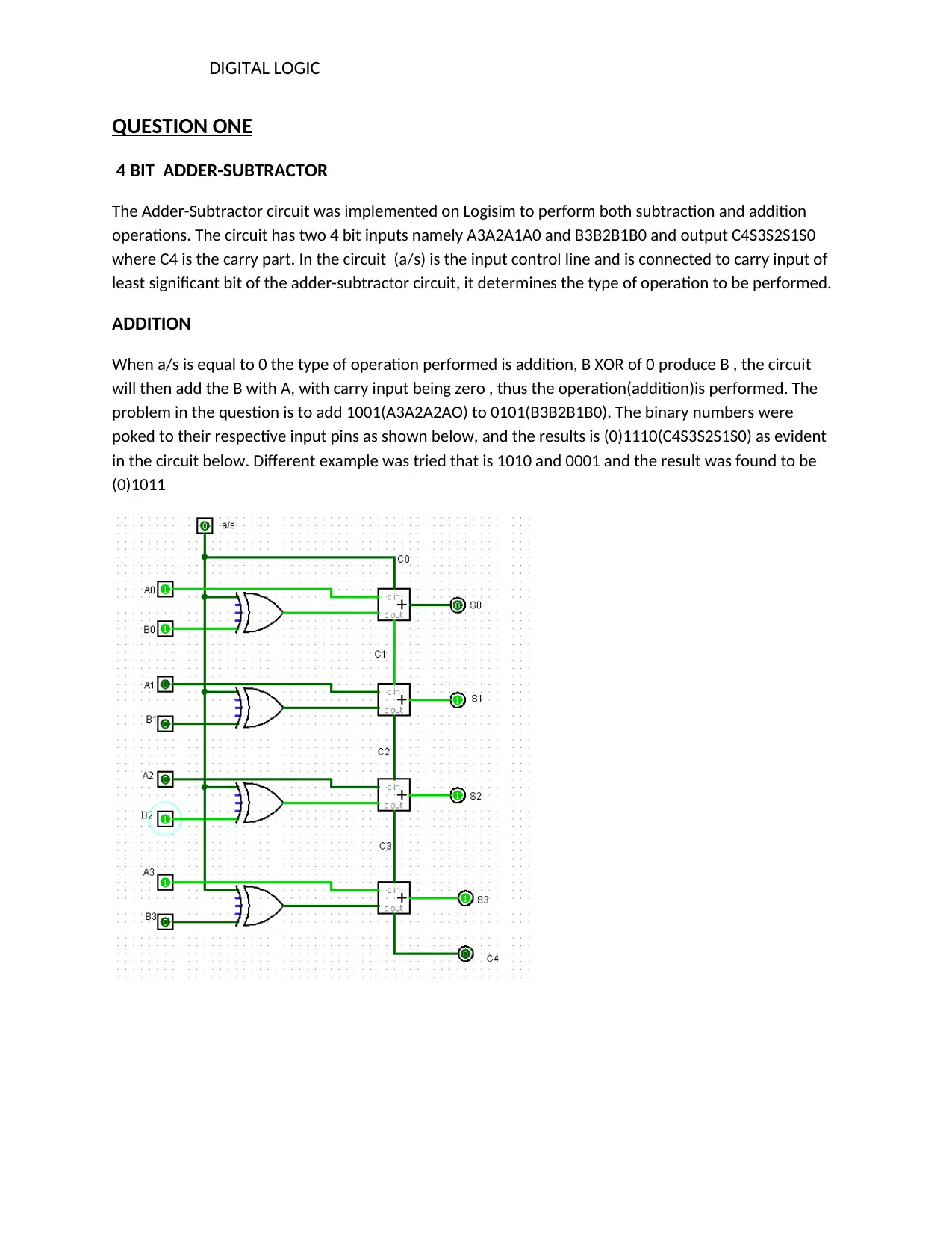
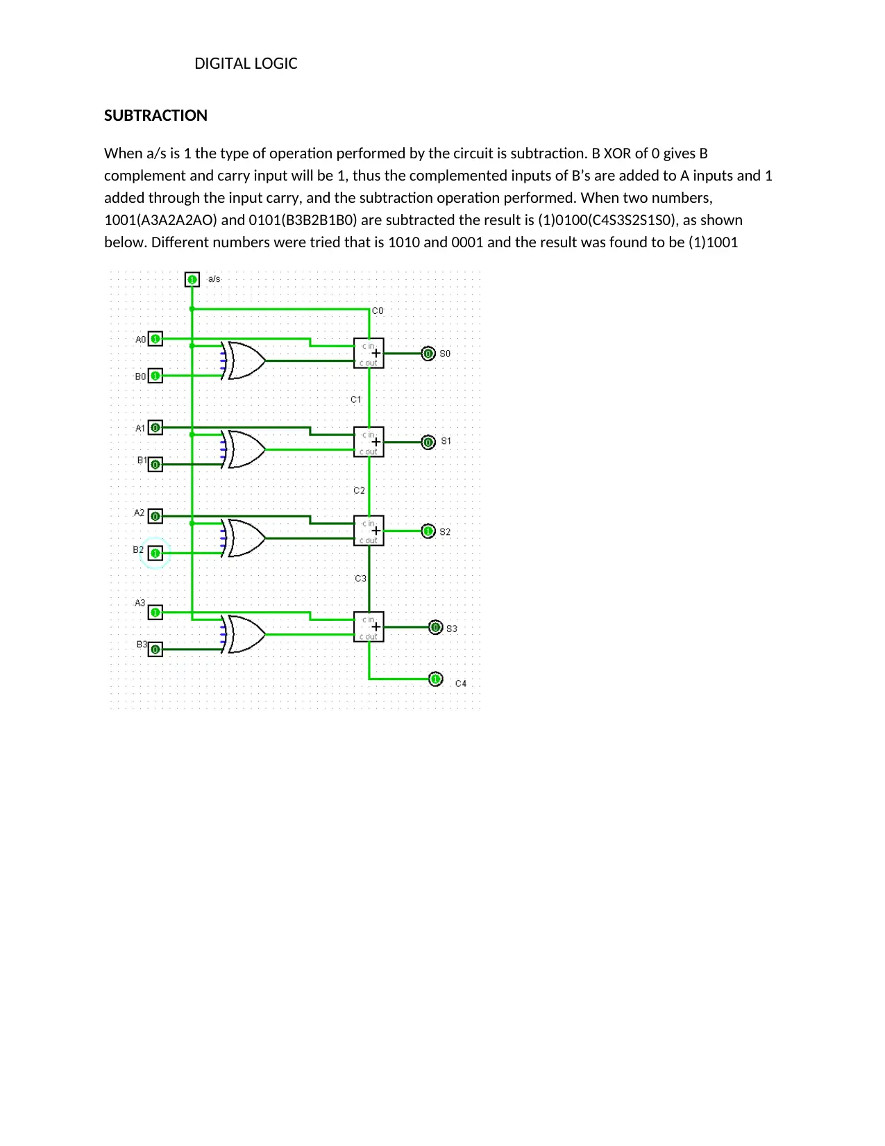
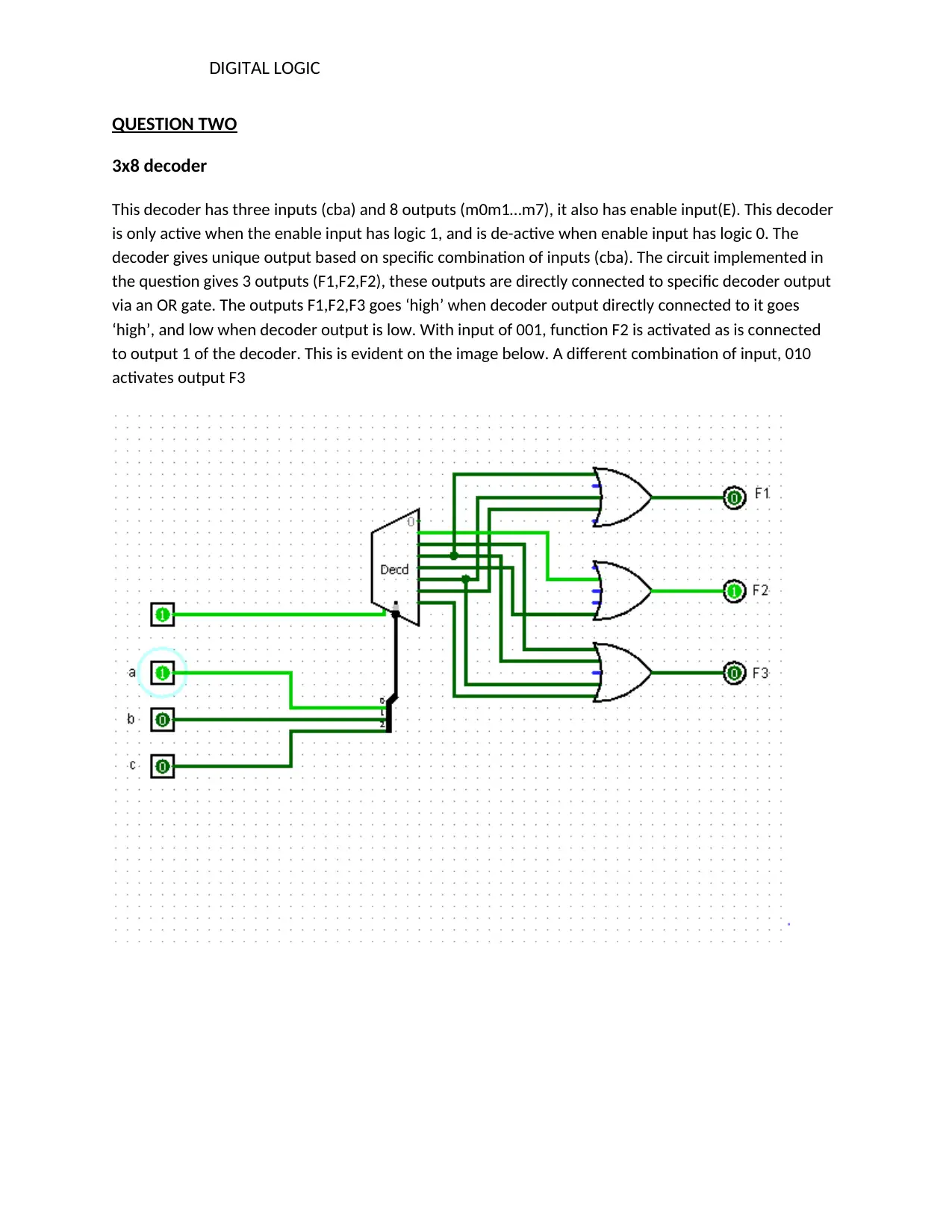
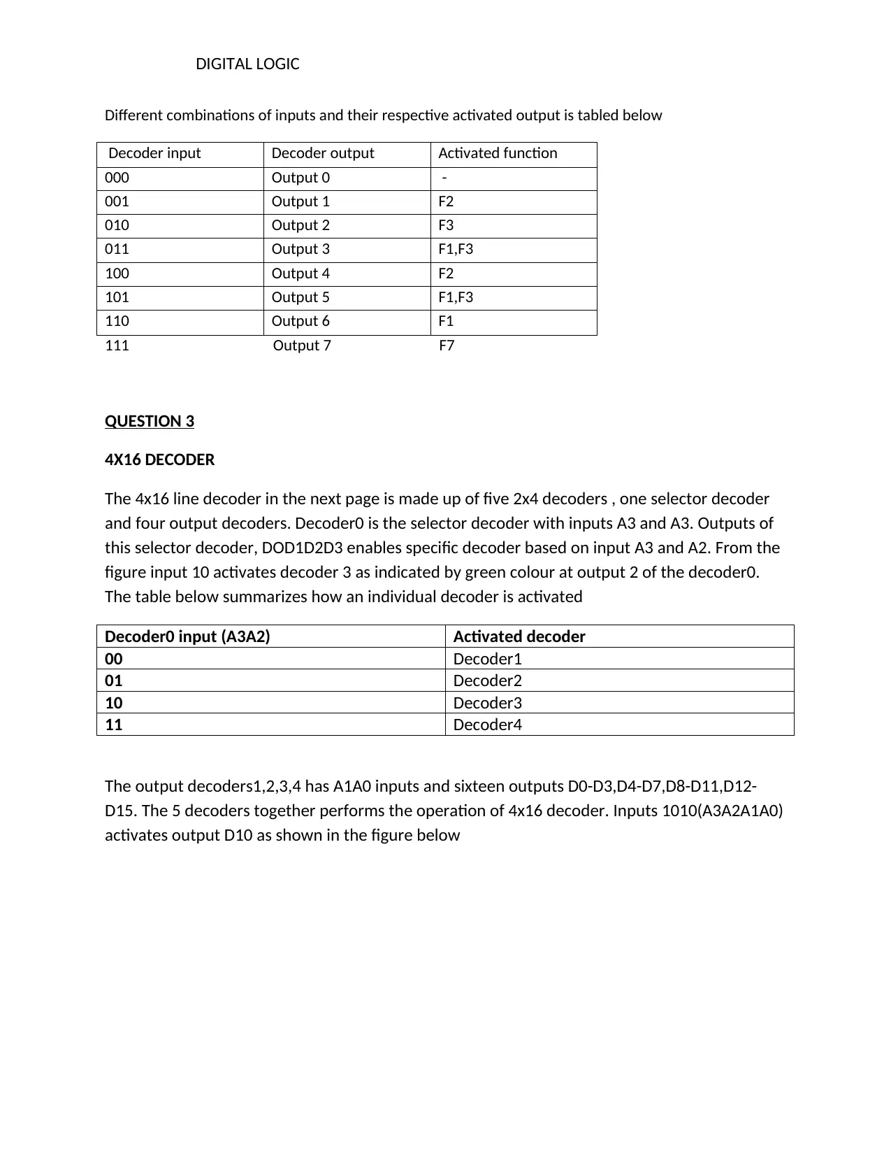
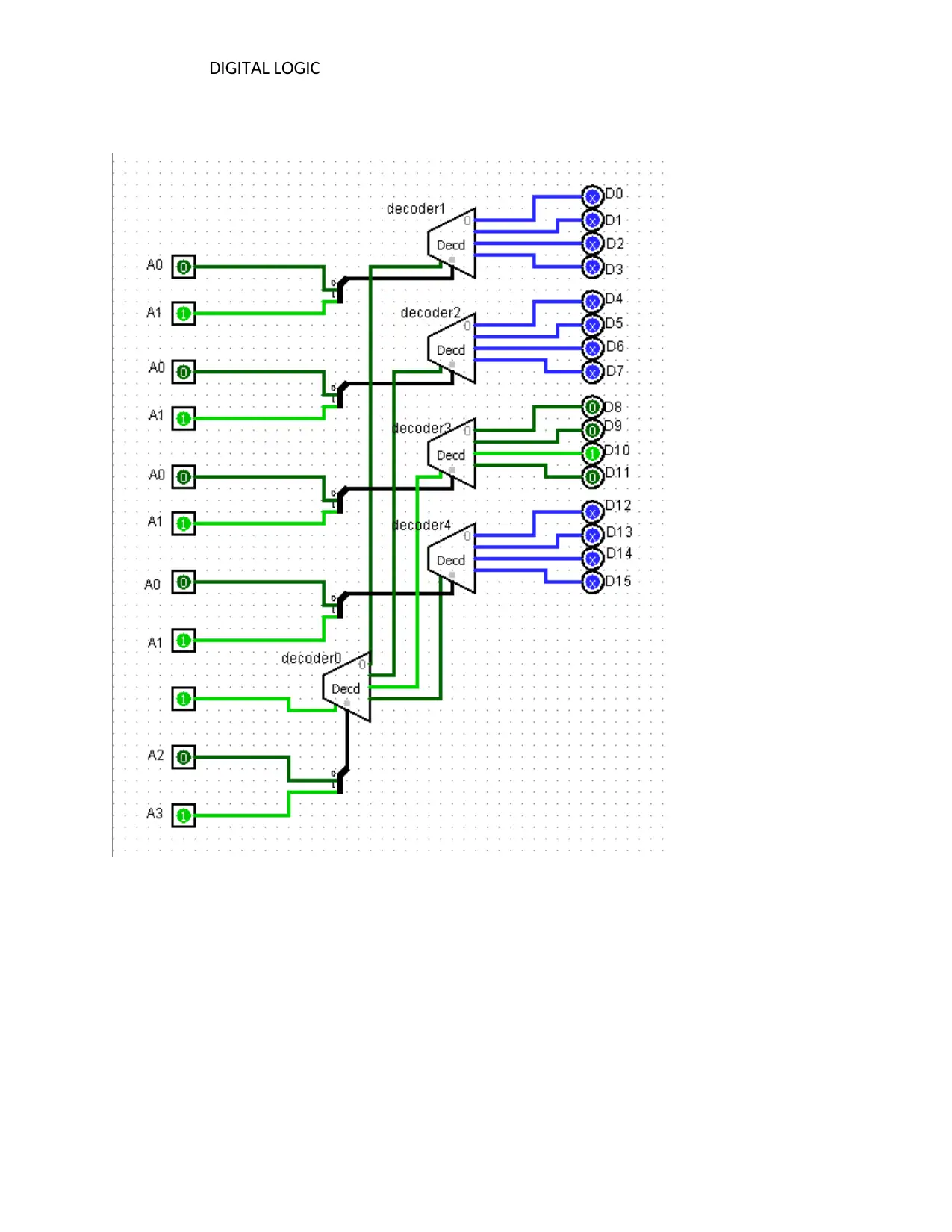
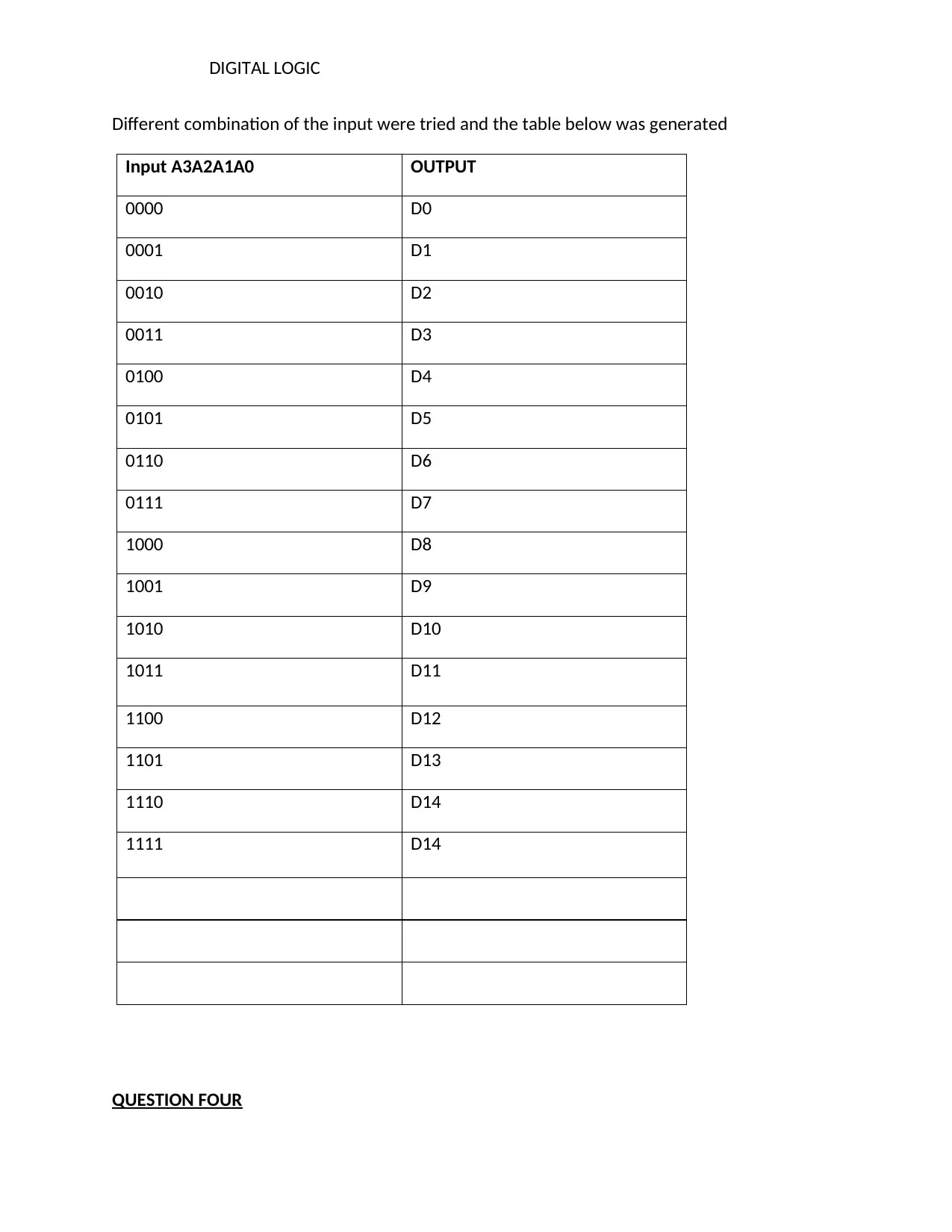
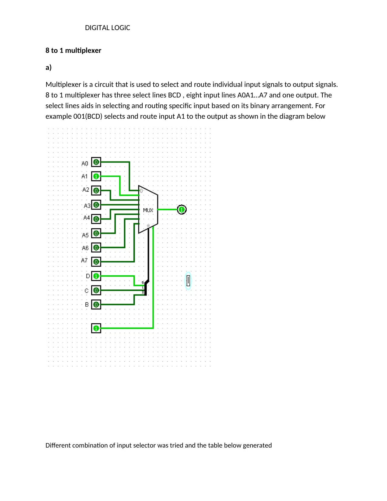
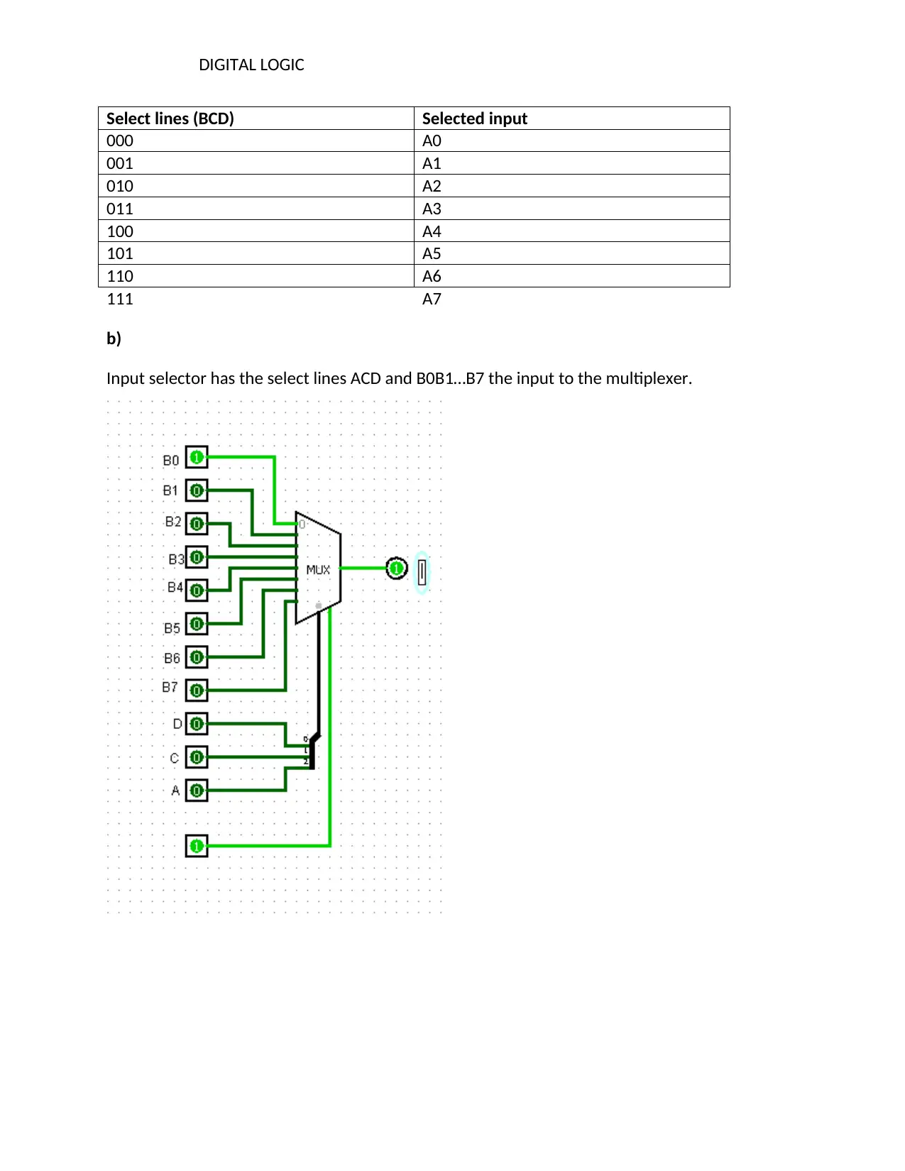
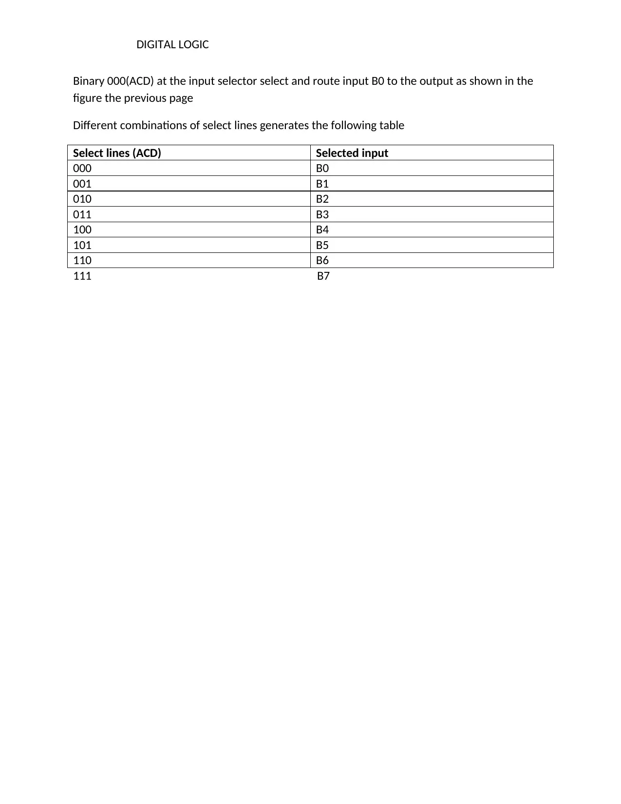
This document provides a detailed analysis and solutions for various digital logic circuits. It begins with an explanation of an adder-subtractor circuit, demonstrating its functionality in both addition and subtraction operations with examples. The solution then explores the 3x8 decoder, explaining its operation, input-output relationships, and how specific outputs are activated based on input combinations. Following this, the document delves into a 4x16 decoder, breaking down its structure composed of smaller decoders and illustrating how different input combinations activate specific outputs. Finally, the document examines 8 to 1 multiplexers, explaining their function in selecting and routing input signals to outputs based on select lines, along with different input selection examples. The document includes tables summarizing input-output relationships for each circuit and provides references for further study.

1 out of 10
Related Documents


Your All-in-One AI-Powered Toolkit for Academic Success.
+13062052269
info@desklib.com
Available 24*7 on WhatsApp / Email
![[object Object]](/_next/static/media/star-bottom.7253800d.svg)
Copyright © 2020–2026 A2Z Services. All Rights Reserved. Developed and managed by ZUCOL.