ECE Lab: Identifying Properties of Synchronous Counter Circuit

Verified

Added on  2023/04/24

|5
|747
|249
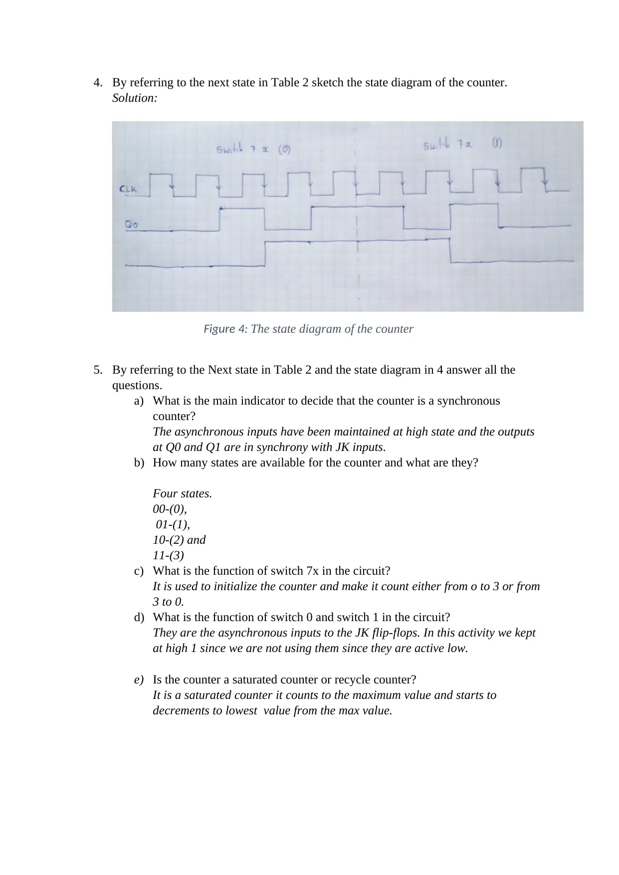
Practical Assignment
AI Summary
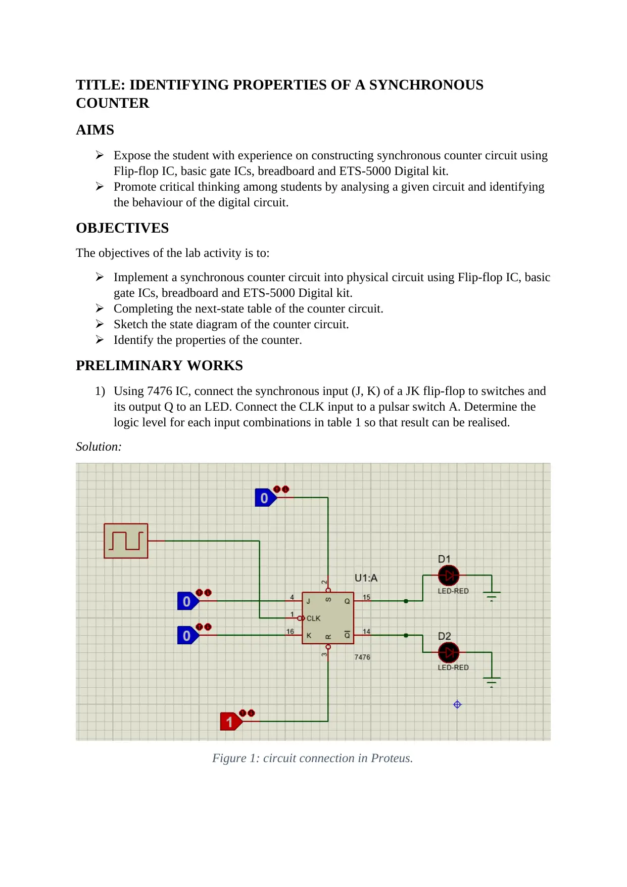
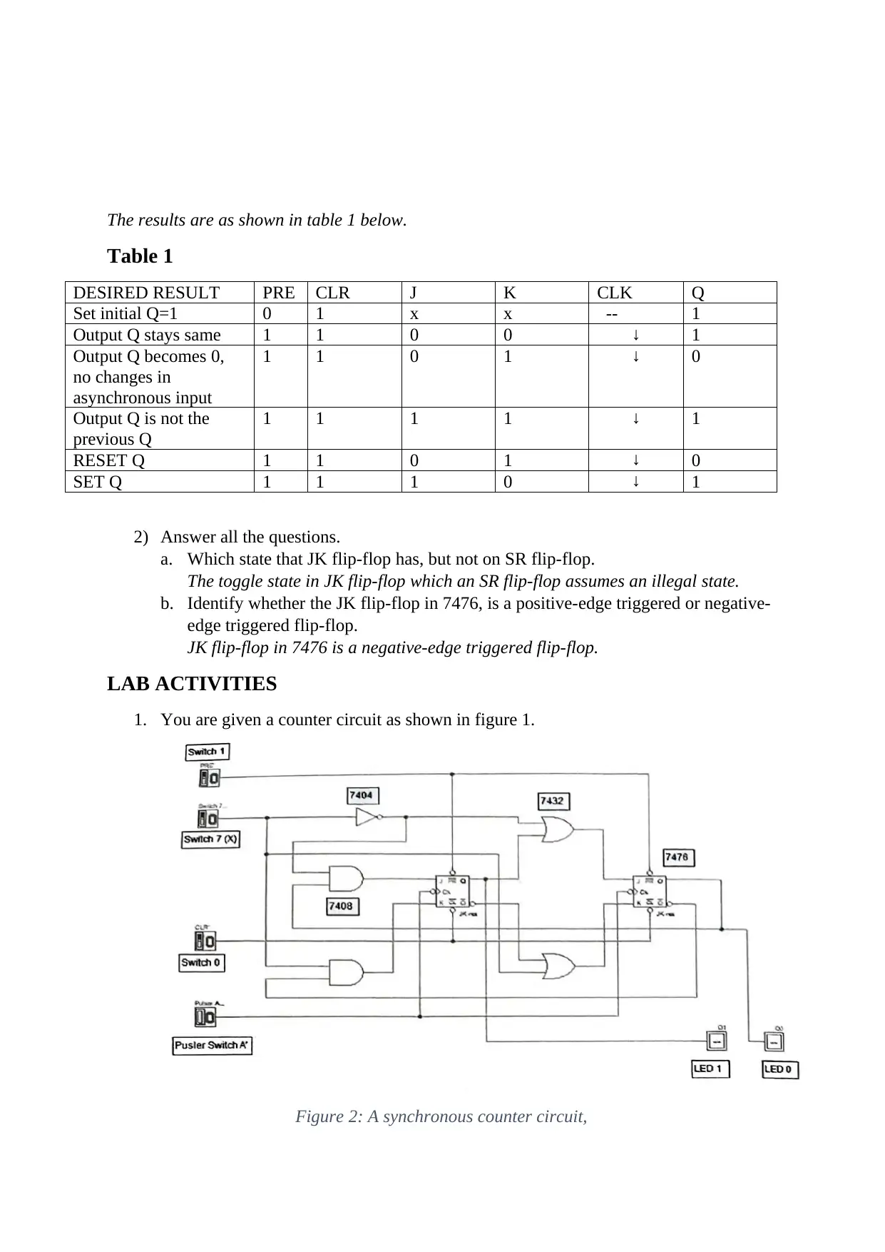
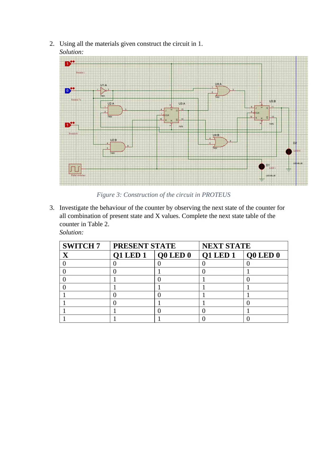
This practical assignment focuses on identifying the properties of a synchronous counter through a hands-on lab experiment. The experiment involves constructing a synchronous counter circuit using JK flip-flop ICs, basic gate ICs, a breadboard, and an ETS-5000 Digital kit. The objectives include implementing the circuit, completing the next-state table, sketching the state diagram, and identifying the counter's properties. The preliminary works involve understanding the behavior of a JK flip-flop and its differences from an SR flip-flop. The lab activities include constructing the counter circuit, investigating its behavior by observing the next state for all combinations of present state and input values, completing the next state table, sketching the state diagram, and answering questions about the counter's characteristics, such as whether it's synchronous, the number of available states, and the function of different switches in the circuit. The report concludes by identifying the counter as a saturated counter.
Document Page
STUDENT’S NAME:
PROFESSOR’S NAME:
TITLE: IDENTIFYING PROPERTIES OF A SYNCHRONOUS
COUNTER
DATE DUE:
SIGNATURE:
tabler-icon-diamond-filled.svg

Secure Best Marks with AI Grader

Need help grading? Try our AI Grader for instant feedback on your assignments.
Document Page
TITLE: IDENTIFYING PROPERTIES OF A SYNCHRONOUS
COUNTER
AIMS
Expose the student with experience on constructing synchronous counter circuit using
Flip-flop IC, basic gate ICs, breadboard and ETS-5000 Digital kit.
Promote critical thinking among students by analysing a given circuit and identifying
the behaviour of the digital circuit.
OBJECTIVES
The objectives of the lab activity is to:
Implement a synchronous counter circuit into physical circuit using Flip-flop IC, basic
gate ICs, breadboard and ETS-5000 Digital kit.
Completing the next-state table of the counter circuit.
Sketch the state diagram of the counter circuit.
Identify the properties of the counter.
PRELIMINARY WORKS
1) Using 7476 IC, connect the synchronous input (J, K) of a JK flip-flop to switches and
its output Q to an LED. Connect the CLK input to a pulsar switch A. Determine the
logic level for each input combinations in table 1 so that result can be realised.
Solution:
Figure 1: circuit connection in Proteus.
Document Page
The results are as shown in table 1 below.
Table 1
DESIRED RESULT PRE CLR J K CLK Q
Set initial Q=1 0 1 x x -- 1
Output Q stays same 1 1 0 0 1
Output Q becomes 0,
no changes in
asynchronous input
1 1 0 1 0
Output Q is not the
previous Q
1 1 1 1 1
RESET Q 1 1 0 1 0
SET Q 1 1 1 0 1
2) Answer all the questions.
a. Which state that JK flip-flop has, but not on SR flip-flop.
The toggle state in JK flip-flop which an SR flip-flop assumes an illegal state.
b. Identify whether the JK flip-flop in 7476, is a positive-edge triggered or negative-
edge triggered flip-flop.
JK flip-flop in 7476 is a negative-edge triggered flip-flop.
LAB ACTIVITIES
1. You are given a counter circuit as shown in figure 1.
Figure 2: A synchronous counter circuit,
Document Page
2. Using all the materials given construct the circuit in 1.
Solution:
Figure 3: Construction of the circuit in PROTEUS
3. Investigate the behaviour of the counter by observing the next state of the counter for
all combination of present state and X values. Complete the next state table of the
counter in Table 2.
Solution:
SWITCH 7 PRESENT STATE NEXT STATE
X Q1 LED 1 Q0 LED 0 Q1 LED 1 Q0 LED 0
0 0 0 0 0
0 0 1 0 1
0 1 0 1 0
0 1 1 1 1
1 0 0 1 1
1 0 1 1 0
1 1 0 0 1
1 1 1 0 0
tabler-icon-diamond-filled.svg

Secure Best Marks with AI Grader

Need help grading? Try our AI Grader for instant feedback on your assignments.
Document Page
4. By referring to the next state in Table 2 sketch the state diagram of the counter.
Solution:
Figure 4: The state diagram of the counter
5. By referring to the Next state in Table 2 and the state diagram in 4 answer all the
questions.
a) What is the main indicator to decide that the counter is a synchronous
counter?
The asynchronous inputs have been maintained at high state and the outputs
at Q0 and Q1 are in synchrony with JK inputs.
b) How many states are available for the counter and what are they?
Four states.
00-(0),
01-(1),
10-(2) and
11-(3)
c) What is the function of switch 7x in the circuit?
It is used to initialize the counter and make it count either from o to 3 or from
3 to 0.
d) What is the function of switch 0 and switch 1 in the circuit?
They are the asynchronous inputs to the JK flip-flops. In this activity we kept
at high 1 since we are not using them since they are active low.
e) Is the counter a saturated counter or recycle counter?
It is a saturated counter it counts to the maximum value and starts to
decrements to lowest value from the max value.
chevron_up_icon
1 out of 5
circle_padding
hide_on_mobile
zoom_out_icon
logo.png

Your All-in-One AI-Powered Toolkit for Academic Success.

Available 24*7 on WhatsApp / Email

[object Object]