Digital Logic and Data Manipulation Coursework - Section B: Solutions
VerifiedAdded on 2019/09/19
|7
|1599
|140
Homework Assignment
AI Summary
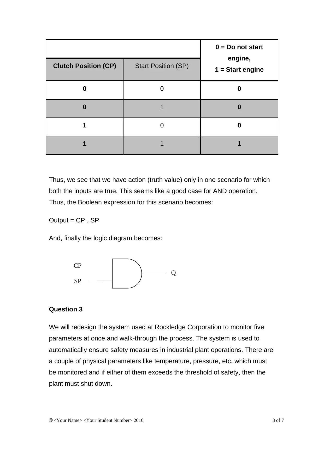
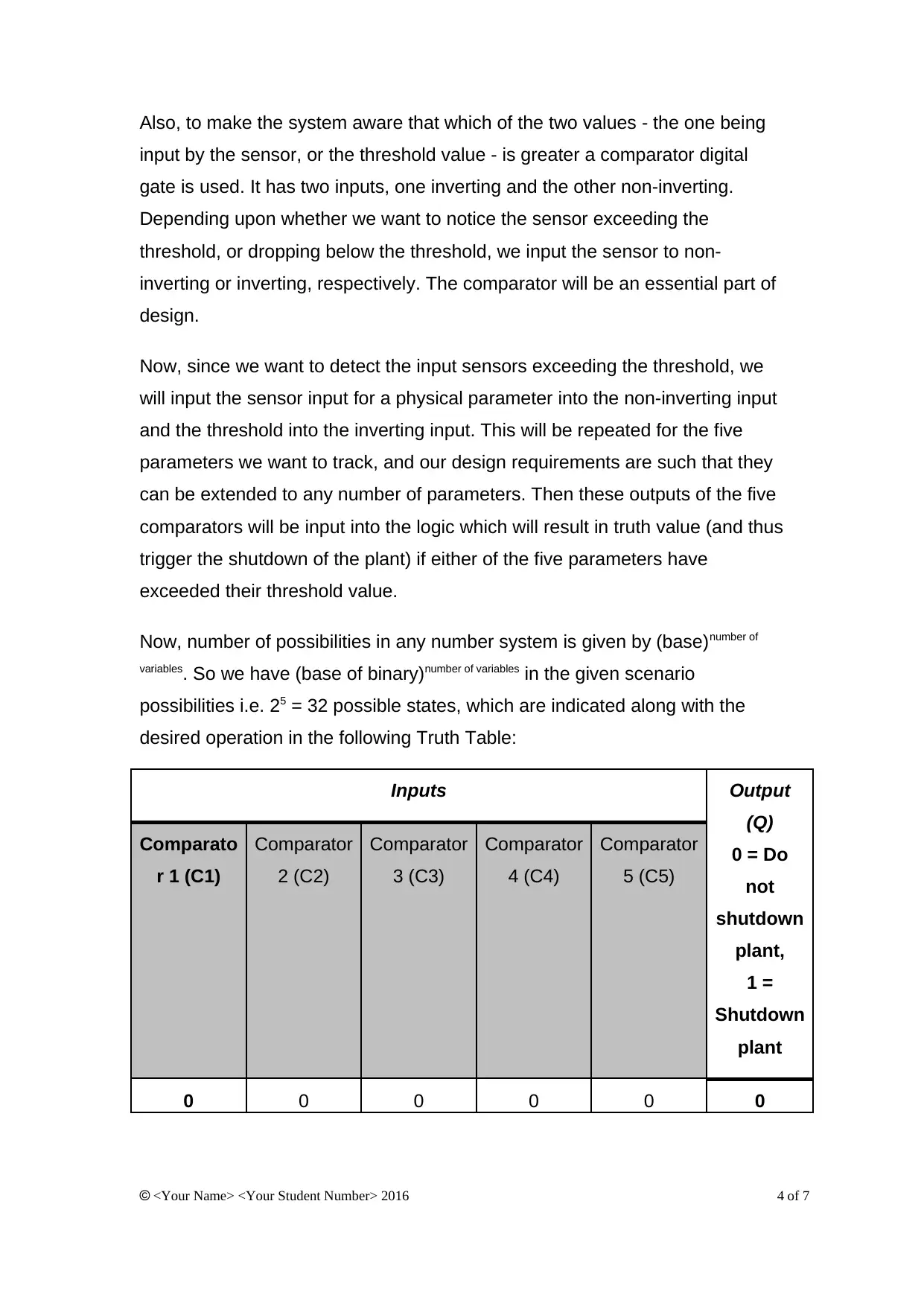
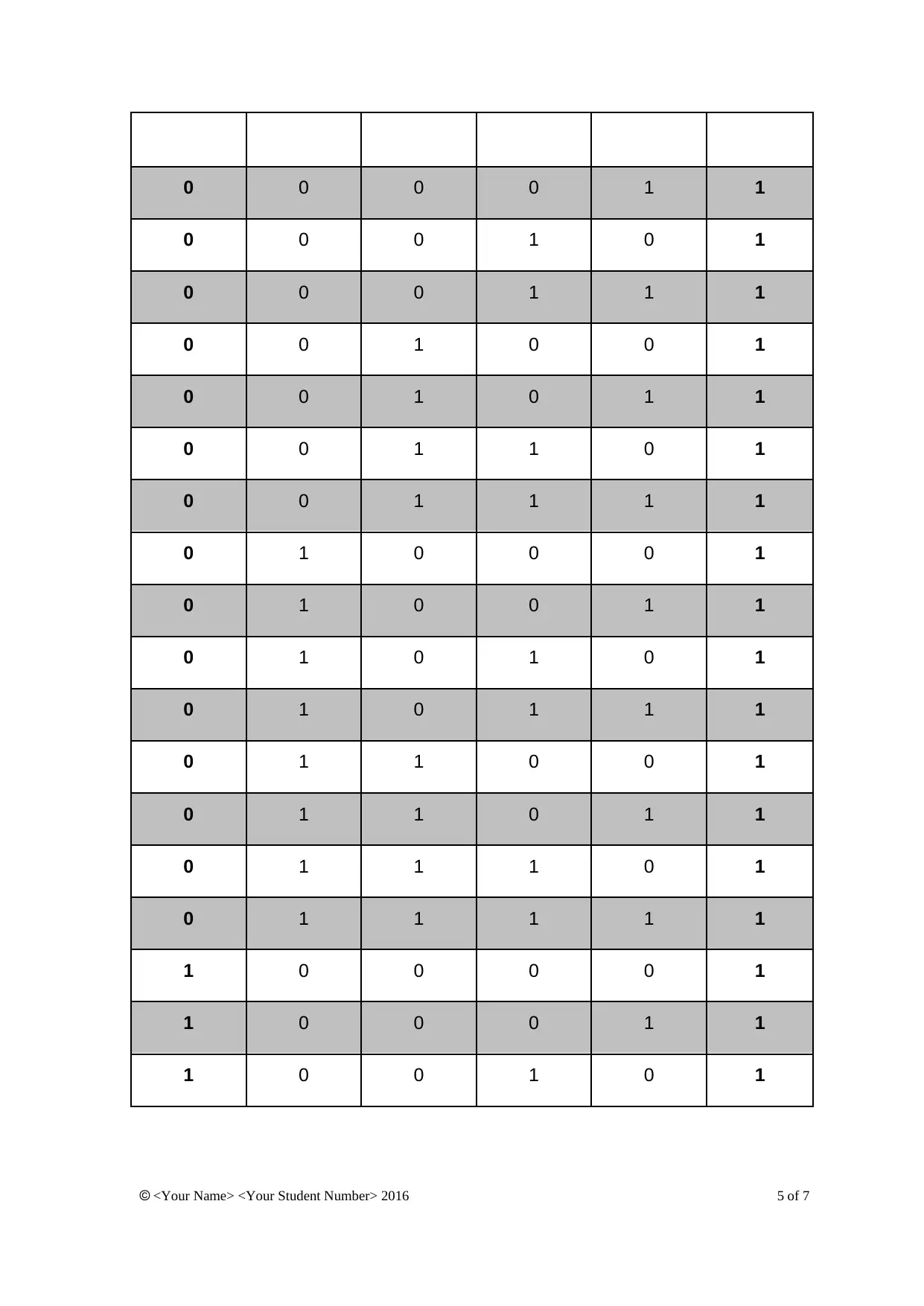
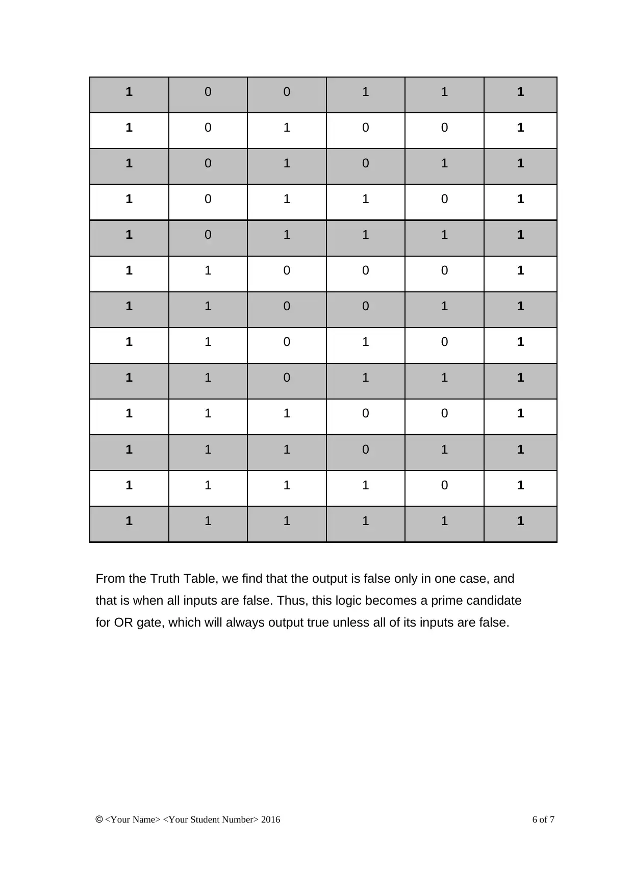
This assignment solution delves into the core concepts of digital logic and data manipulation, beginning with an exploration of why binary number systems are fundamental to modern digital computers. The solution elucidates the advantages of binary, including ease of design and manufacture, low power consumption, noise immunity, and compatibility with hardware. It then presents solutions to specific problems involving circuit design and analysis. Question 2 focuses on designing a logic circuit for a car's ignition system, utilizing a truth table to derive the Boolean expression and logic diagram for an AND gate. Question 3 extends this to a safety monitoring system in an industrial plant, where multiple parameters are tracked using comparators and an OR gate is used to trigger a shutdown if any parameter exceeds its threshold. The assignment solution demonstrates a thorough understanding of digital logic principles and their practical applications in circuit design.

DIGITAL LOGIC AND DATA MANIPULATION COURSEWORK - SECTION B
Question 1
Modern-day digital computers can run complex applications, and that too in a
small form and by consuming less power as compared to earlier generations
of computers (DeMone, 2004). This has been enabled by the decision to base
modern electronics internal working on binary number systems (Blinnikov,
2010).
Now, we explore why binary number system is used for modern-day digital
computers and not any other say decimal (base 10), octal (base 8),
hexadecimal (base 16) or any other arbitrary number-system base.
Ease of Design / Manufacture / Low Costs
It is easier to design a computer's internal system when we are dealing with
the minimum number of discrete states (Saha and Mukherjee, 2016) and two
is the lowest base number that can satisfy the mathematical requirements
from a digital computer (cs.stackexchange.com, 2014). This is confirmed by
Kjell, (n.d.) that binary is simple and easy to build, and it is this simplicity also
allows us to easily combine components into sophisticated systems (Harris
and Harris, 2015). This also reflects in cheaper manufacture and lower costs
(Clements, 2006).
Low Power Consumption
Every state to be represented in a digital circuit will require a separate band of
voltage, thus more states (e.g. ten states in decimal system) will require ten
separate voltage bands and thus will consume more power. And as per N
(n.d.) we do not see any gains for a digital computer by increasing the number
of states, so there is no reason to have a higher-consumption circuit.
Noise Immunity / Reliability
<Your Name> <Your Student Number> 2016 1 of 7
Secure Best Marks with AI Grader
Need help grading? Try our AI Grader for instant feedback on your assignments.

The physical circuits may be using discrete logic (binary or any other), but
they are still using analog signals (electricity) to work. Analog signals move
from one value to another smoothly and not abruptly. Thus, we need gaps or
steps around the chosen voltage bands to unambiguously identify the state
being represented. An additional impetus for reducing the number of states is
the fact that electronic signals are not always very steady and can vary
because of surrounding influences N (n.d.). Thus, the circuits are much more
reliable when only two states are concerned.
Compatibility With Other Hardware
In addition, most hardware used along with a computer is bi-state i.e. having
either of the two states possible On or Off e.g. (magnetic) hard disks'
elemental storage unit can be magnetised (On) or not magnetised (Off); an
optical disk (DVD, CD)'s elemental storage unit can reflect a light or not reflect
a light to indicate the two states possible; a fiber optic cable can send a pulse
of light (On) or not send any light i.e. darkness (Off) to indicate the two states
possible.
Question 2
For the given scenario of proposed car's ignition system, we have two
variables to consider - starting the ignition (say start position, SP) and
pressing of clutch (say clutch position, CP). Both of these variables are binary,
with the states mentioned below:
SP: 1 = starting the ignition, 0 = ignition is off, or the engine is running
CP: 1 = clutch is depressed, 0 = clutch is not pressed i.e. normal position
Now, number of possibilities in any number system is given by (base)number of
variables. So we have (base of binary)number of variables in the given scenario
possibilities i.e. 22 = 4 possible states, which are indicated along with the
desired operation in the following Truth Table:
Inputs Output (Q)
<Your Name> <Your Student Number> 2016 2 of 7

CP
SP
Q
0 = Do not start
engine,
1 = Start engine
Clutch Position (CP) Start Position (SP)
0 0 0
0 1 0
1 0 0
1 1 1
Thus, we see that we have action (truth value) only in one scenario for which
both the inputs are true. This seems like a good case for AND operation.
Thus, the Boolean expression for this scenario becomes:
Output = CP . SP
And, finally the logic diagram becomes:
Question 3
We will redesign the system used at Rockledge Corporation to monitor five
parameters at once and walk-through the process. The system is used to
automatically ensure safety measures in industrial plant operations. There are
a couple of physical parameters like temperature, pressure, etc. which must
be monitored and if either of them exceeds the threshold of safety, then the
plant must shut down.
<Your Name> <Your Student Number> 2016 3 of 7

Also, to make the system aware that which of the two values - the one being
input by the sensor, or the threshold value - is greater a comparator digital
gate is used. It has two inputs, one inverting and the other non-inverting.
Depending upon whether we want to notice the sensor exceeding the
threshold, or dropping below the threshold, we input the sensor to non-
inverting or inverting, respectively. The comparator will be an essential part of
design.
Now, since we want to detect the input sensors exceeding the threshold, we
will input the sensor input for a physical parameter into the non-inverting input
and the threshold into the inverting input. This will be repeated for the five
parameters we want to track, and our design requirements are such that they
can be extended to any number of parameters. Then these outputs of the five
comparators will be input into the logic which will result in truth value (and thus
trigger the shutdown of the plant) if either of the five parameters have
exceeded their threshold value.
Now, number of possibilities in any number system is given by (base)number of
variables. So we have (base of binary)number of variables in the given scenario
possibilities i.e. 25 = 32 possible states, which are indicated along with the
desired operation in the following Truth Table:
Inputs Output
(Q)
0 = Do
not
shutdown
plant,
1 =
Shutdown
plant
Comparato
r 1 (C1)
Comparator
2 (C2)
Comparator
3 (C3)
Comparator
4 (C4)
Comparator
5 (C5)
0 0 0 0 0 0
<Your Name> <Your Student Number> 2016 4 of 7
Secure Best Marks with AI Grader
Need help grading? Try our AI Grader for instant feedback on your assignments.

0 0 0 0 1 1
0 0 0 1 0 1
0 0 0 1 1 1
0 0 1 0 0 1
0 0 1 0 1 1
0 0 1 1 0 1
0 0 1 1 1 1
0 1 0 0 0 1
0 1 0 0 1 1
0 1 0 1 0 1
0 1 0 1 1 1
0 1 1 0 0 1
0 1 1 0 1 1
0 1 1 1 0 1
0 1 1 1 1 1
1 0 0 0 0 1
1 0 0 0 1 1
1 0 0 1 0 1
<Your Name> <Your Student Number> 2016 5 of 7
0 0 0 1 0 1
0 0 0 1 1 1
0 0 1 0 0 1
0 0 1 0 1 1
0 0 1 1 0 1
0 0 1 1 1 1
0 1 0 0 0 1
0 1 0 0 1 1
0 1 0 1 0 1
0 1 0 1 1 1
0 1 1 0 0 1
0 1 1 0 1 1
0 1 1 1 0 1
0 1 1 1 1 1
1 0 0 0 0 1
1 0 0 0 1 1
1 0 0 1 0 1
<Your Name> <Your Student Number> 2016 5 of 7

1 0 0 1 1 1
1 0 1 0 0 1
1 0 1 0 1 1
1 0 1 1 0 1
1 0 1 1 1 1
1 1 0 0 0 1
1 1 0 0 1 1
1 1 0 1 0 1
1 1 0 1 1 1
1 1 1 0 0 1
1 1 1 0 1 1
1 1 1 1 0 1
1 1 1 1 1 1
From the Truth Table, we find that the output is false only in one case, and
that is when all inputs are false. Thus, this logic becomes a prime candidate
for OR gate, which will always output true unless all of its inputs are false.
<Your Name> <Your Student Number> 2016 6 of 7

References
Blinnikov, L. (2010). Why Computers Use Binary. [online] Nookkin.com.
Available at: http://nookkin.com/articles/computer-science/why-computers-
use-binary.ndoc [Accessed 9 Dec. 2016].
Clements, A. (2006). The principles of computer hardware. 1st ed. Oxford:
Oxford University Press, p.145.
DeMone, P. (2004). The Incredible Shrinking CPU. [online]
Realworldtech.com. Available at: http://www.realworldtech.com/shrinking-cpu/
[Accessed 9 Dec. 2016].
Harris, S. and Harris, D. (2015). Digital Design and Computer Architecture:
ARM Edition. 1st ed. Morgan Kaufmann, p.6.
Kjell, B. (n.d.). Advantage of Binary 2: Unambiguous Signals. [online]
Chortle.ccsu.edu. Available at:
http://chortle.ccsu.edu/java5/Notes/chap02/ch02_6.html [Accessed 9 Dec.
2016].
N, T. (n.d.). Why do computers use binary numbers? [Answered]. [online]
Penjee, Learn to Code. Available at: https://blog.penjee.com/why-do-
computers-use-binary-numbers-answered/ [Accessed 9 Dec. 2016].
Saha, S. and Mukherjee, S. (2016). Basic computation and programming with
C. 1st ed. Cambridge University Press, p.15.
cs.stackexchange.com. (2014). Why Do Computers Use the Binary Number
System (0,1)?. [online] Available at: http://cs.stackexchange.com/a/27684/
[Accessed 9 Dec. 2016].
<Your Name> <Your Student Number> 2016 7 of 7
1 out of 7

Your All-in-One AI-Powered Toolkit for Academic Success.
+13062052269
info@desklib.com
Available 24*7 on WhatsApp / Email
Unlock your academic potential
© 2024 | Zucol Services PVT LTD | All rights reserved.