Digital Logic Design and Implementation: VHDL Circuits and Testbenches
VerifiedAdded on 2020/04/13
|15
|2132
|392
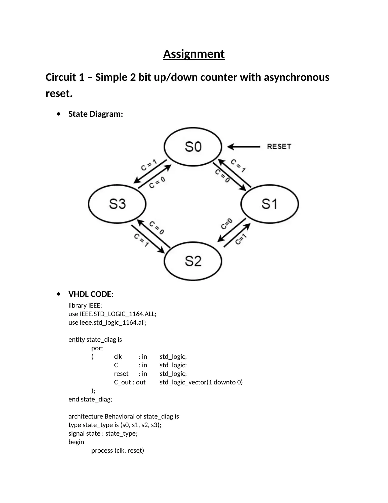
Practical Assignment
AI Summary
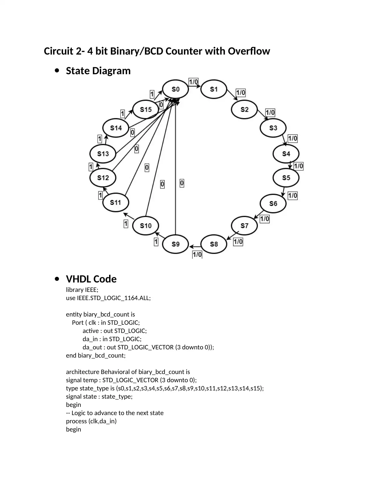
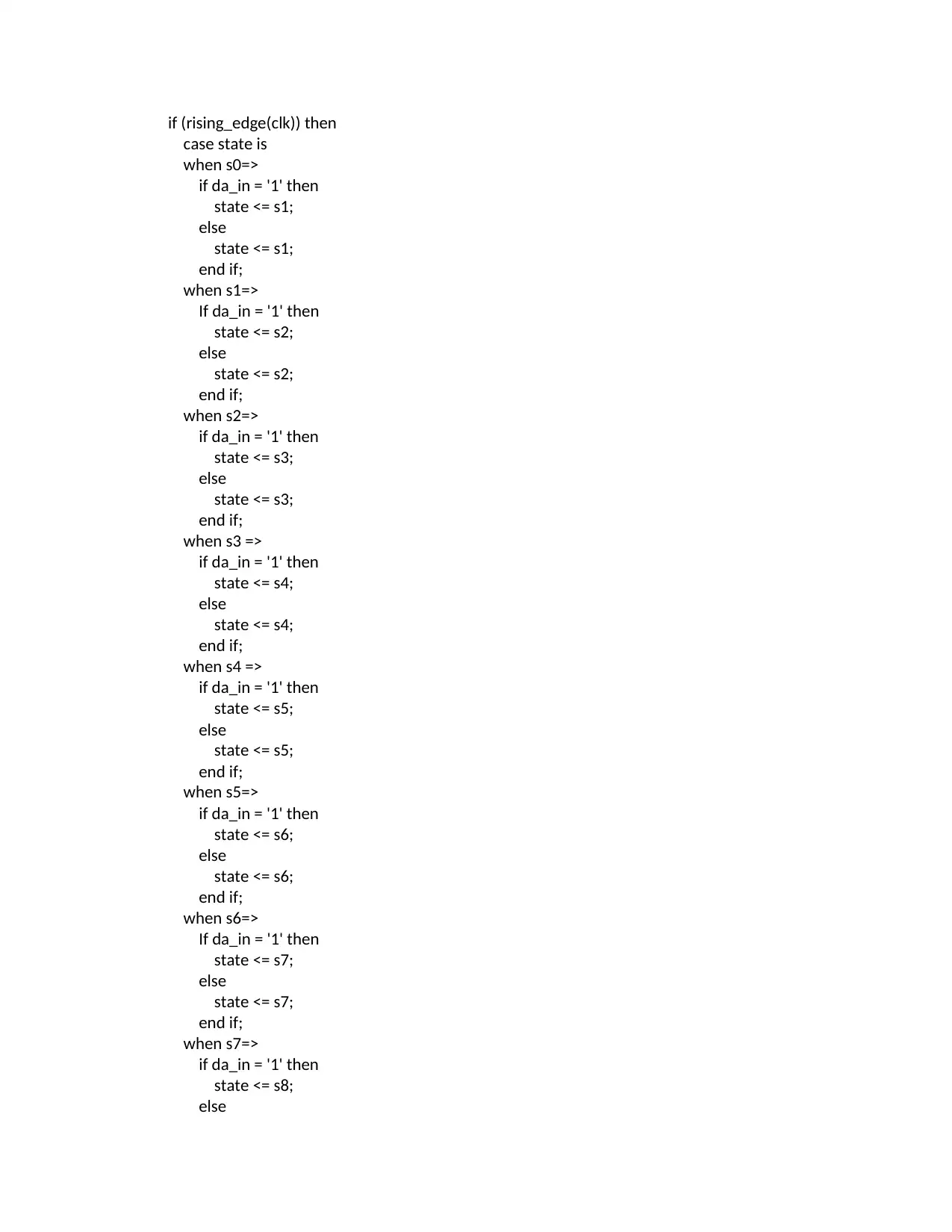
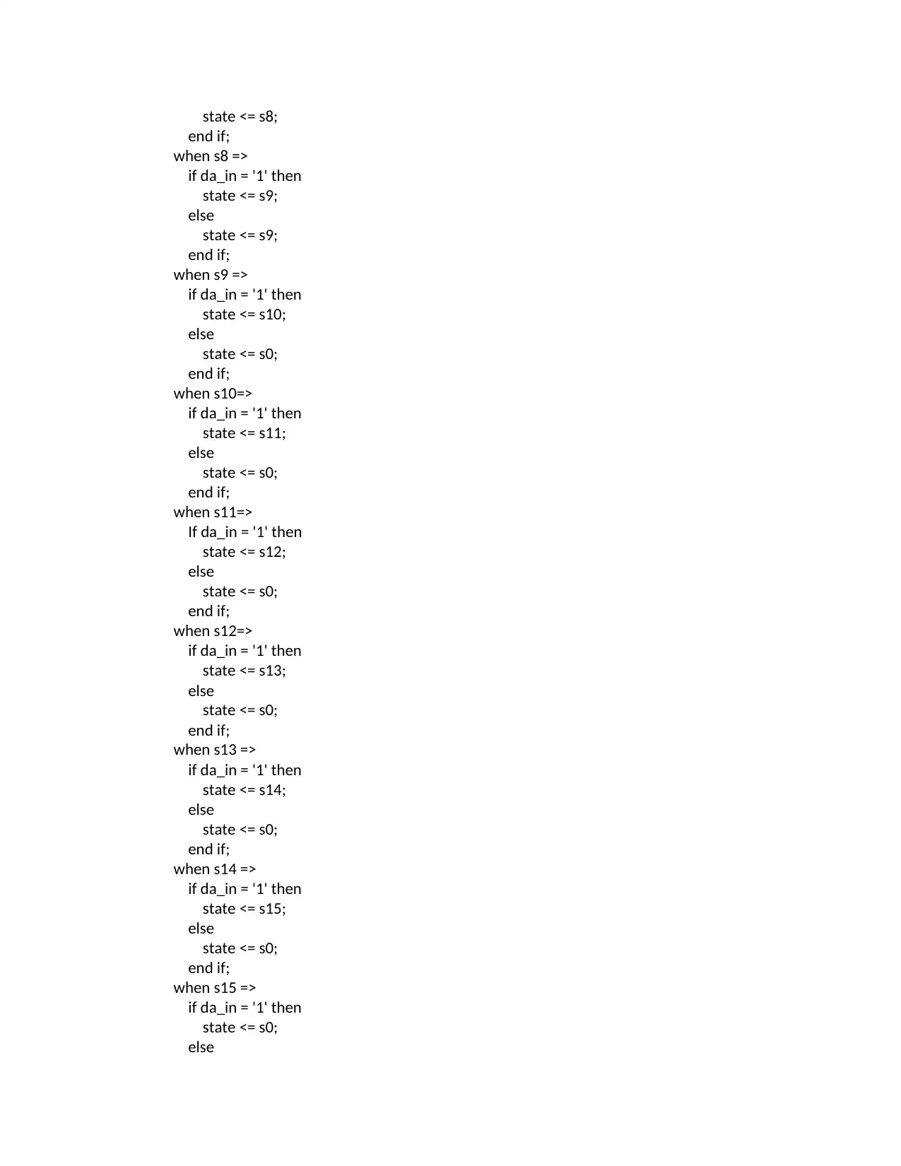
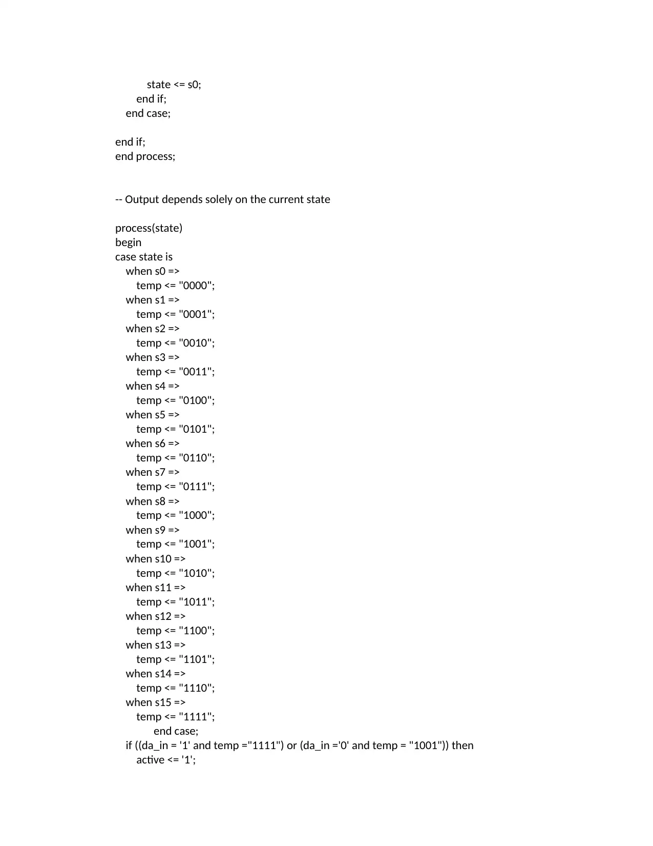
This document presents the solutions for a digital logic circuit design assignment, detailing the implementation of three distinct circuits using VHDL. The first circuit is a 2-bit up/down counter with an asynchronous reset, including its state diagram, VHDL code, and a testbench for verification. The second circuit is a 4-bit binary/BCD counter with an overflow detection mechanism, complete with state diagrams, VHDL code, and a testbench. The final circuit is a timing delay module, featuring a state diagram, VHDL code, and a testbench to simulate its behavior. Each circuit solution includes VHDL code for the design and a corresponding testbench for simulation and verification, along with waveform reports to illustrate the circuit's functionality and timing characteristics. This comprehensive approach provides a detailed guide to understanding and implementing digital logic circuits using VHDL, suitable for electrical engineering students.

Assignment
Circuit 1 – Simple 2 bit up/down counter with asynchronous
reset.
State Diagram:
VHDL CODE:
library IEEE;
use IEEE.STD_LOGIC_1164.ALL;
use ieee.std_logic_1164.all;
entity state_diag is
port
( clk : in std_logic;
C : in std_logic;
reset : in std_logic;
C_out : out std_logic_vector(1 downto 0)
);
end state_diag;
architecture Behavioral of state_diag is
type state_type is (s0, s1, s2, s3);
signal state : state_type;
begin
process (clk, reset)
Paraphrase This Document
Need a fresh take? Get an instant paraphrase of this document with our AI Paraphraser

begin
if reset = '1' then
state <= s0;
elsif (rising_edge(clk)) then
case state is
when s0=>
if C = '0' then
state <= s1;
else
state <= s3;
end if;
when s1=>
if C = '0' then
state <= s2;
else
state <= s0;
end if;
when s2=>
if C = '0' then
state <= s3;
else
state <= s1;
end if;
when s3=>
if C = '0' then
state <= s0;
else
state <= s2;
end if;
end case;
end if;
end process;
process (state, C)
begin
case state is
when s0=>
C_out <= "00";
when s1=>
C_out <= "01";
when s2=>
C_out <= "10";
when s3=>
C_out <= "11";
end case;
end process;
end Behavioral;

TESTBENCH CODE:
Library IEEE;
use IEEE.STD_LOGIC_1164.ALL;
entity state_diag_tb is
-- Port ( );
end state_diag_tb;
architecture Behavioral of state_diag_tb is
component state_diag is
port
( clk : in std_logic;
C : in std_logic;
reset : in std_logic;
C_out : out std_logic_vector(1 downto 0)
);
end component;
signal clk : STD_LOGIC := '0';
signal rst : STD_LOGIC := '1';
signal x1 : STD_LOGIC := '0';
signal y1 : STD_LOGIC_VECTOR(1 downto 0);
begin
uut : state_diag port map(clk=>clk,reset => rst, C=>x1,C_out=>y1);
clock : process
begin
clk <= not clk after 10 ns;
wait for 20 ns;
end process;
reset : process
⊘ This is a preview!⊘
Do you want full access?
Subscribe today to unlock all pages.

Trusted by 1+ million students worldwide

begin
rst <= not rst after 10 ns;
wait for 200 ns;
end process;
input : process
begin
x1 <= not x1 after 15 ns;
wait for 30 ns;
end process;
end Behavioral;
REPORT:
o Waveform
Here x1 input is variable C.
rst <= not rst after 10 ns;
wait for 200 ns;
end process;
input : process
begin
x1 <= not x1 after 15 ns;
wait for 30 ns;
end process;
end Behavioral;
REPORT:
o Waveform
Here x1 input is variable C.
Paraphrase This Document
Need a fresh take? Get an instant paraphrase of this document with our AI Paraphraser

Circuit 2- 4 bit Binary/BCD Counter with Overflow
State Diagram
VHDL Code
library IEEE;
use IEEE.STD_LOGIC_1164.ALL;
entity biary_bcd_count is
Port ( clk : in STD_LOGIC;
active : out STD_LOGIC;
da_in : in STD_LOGIC;
da_out : out STD_LOGIC_VECTOR (3 downto 0));
end biary_bcd_count;
architecture Behavioral of biary_bcd_count is
signal temp : STD_LOGIC_VECTOR (3 downto 0);
type state_type is (s0,s1,s2,s3,s4,s5,s6,s7,s8,s9,s10,s11,s12,s13,s14,s15);
signal state : state_type;
begin
-- Logic to advance to the next state
process (clk,da_in)
begin

if (rising_edge(clk)) then
case state is
when s0=>
if da_in = '1' then
state <= s1;
else
state <= s1;
end if;
when s1=>
If da_in = '1' then
state <= s2;
else
state <= s2;
end if;
when s2=>
if da_in = '1' then
state <= s3;
else
state <= s3;
end if;
when s3 =>
if da_in = '1' then
state <= s4;
else
state <= s4;
end if;
when s4 =>
if da_in = '1' then
state <= s5;
else
state <= s5;
end if;
when s5=>
if da_in = '1' then
state <= s6;
else
state <= s6;
end if;
when s6=>
If da_in = '1' then
state <= s7;
else
state <= s7;
end if;
when s7=>
if da_in = '1' then
state <= s8;
else
⊘ This is a preview!⊘
Do you want full access?
Subscribe today to unlock all pages.

Trusted by 1+ million students worldwide

state <= s8;
end if;
when s8 =>
if da_in = '1' then
state <= s9;
else
state <= s9;
end if;
when s9 =>
if da_in = '1' then
state <= s10;
else
state <= s0;
end if;
when s10=>
if da_in = '1' then
state <= s11;
else
state <= s0;
end if;
when s11=>
If da_in = '1' then
state <= s12;
else
state <= s0;
end if;
when s12=>
if da_in = '1' then
state <= s13;
else
state <= s0;
end if;
when s13 =>
if da_in = '1' then
state <= s14;
else
state <= s0;
end if;
when s14 =>
if da_in = '1' then
state <= s15;
else
state <= s0;
end if;
when s15 =>
if da_in = '1' then
state <= s0;
else
end if;
when s8 =>
if da_in = '1' then
state <= s9;
else
state <= s9;
end if;
when s9 =>
if da_in = '1' then
state <= s10;
else
state <= s0;
end if;
when s10=>
if da_in = '1' then
state <= s11;
else
state <= s0;
end if;
when s11=>
If da_in = '1' then
state <= s12;
else
state <= s0;
end if;
when s12=>
if da_in = '1' then
state <= s13;
else
state <= s0;
end if;
when s13 =>
if da_in = '1' then
state <= s14;
else
state <= s0;
end if;
when s14 =>
if da_in = '1' then
state <= s15;
else
state <= s0;
end if;
when s15 =>
if da_in = '1' then
state <= s0;
else
Paraphrase This Document
Need a fresh take? Get an instant paraphrase of this document with our AI Paraphraser

state <= s0;
end if;
end case;
end if;
end process;
-- Output depends solely on the current state
process(state)
begin
case state is
when s0 =>
temp <= "0000";
when s1 =>
temp <= "0001";
when s2 =>
temp <= "0010";
when s3 =>
temp <= "0011";
when s4 =>
temp <= "0100";
when s5 =>
temp <= "0101";
when s6 =>
temp <= "0110";
when s7 =>
temp <= "0111";
when s8 =>
temp <= "1000";
when s9 =>
temp <= "1001";
when s10 =>
temp <= "1010";
when s11 =>
temp <= "1011";
when s12 =>
temp <= "1100";
when s13 =>
temp <= "1101";
when s14 =>
temp <= "1110";
when s15 =>
temp <= "1111";
end case;
if ((da_in = '1' and temp ="1111") or (da_in ='0' and temp = "1001")) then
active <= '1';
end if;
end case;
end if;
end process;
-- Output depends solely on the current state
process(state)
begin
case state is
when s0 =>
temp <= "0000";
when s1 =>
temp <= "0001";
when s2 =>
temp <= "0010";
when s3 =>
temp <= "0011";
when s4 =>
temp <= "0100";
when s5 =>
temp <= "0101";
when s6 =>
temp <= "0110";
when s7 =>
temp <= "0111";
when s8 =>
temp <= "1000";
when s9 =>
temp <= "1001";
when s10 =>
temp <= "1010";
when s11 =>
temp <= "1011";
when s12 =>
temp <= "1100";
when s13 =>
temp <= "1101";
when s14 =>
temp <= "1110";
when s15 =>
temp <= "1111";
end case;
if ((da_in = '1' and temp ="1111") or (da_in ='0' and temp = "1001")) then
active <= '1';

else
active <='0';
end if;
da_out <= temp;
end process;
o Testbench Code
library IEEE;
use IEEE.STD_LOGIC_1164.ALL;
entity biary_bcd_count_tb is
-- Port ( );
end biary_bcd_count_tb;
architecture Behavioral of biary_bcd_count_tb is
component biary_bcd_count is
Port ( clk : in STD_LOGIC;
active : out STD_LOGIC;
da_in : in STD_LOGIC;
da_out : out STD_LOGIC_VECTOR (3 downto 0));
end component;
signal clk : STD_LOGIC := '0';
signal act : STD_LOGIC;
signal x1 : STD_LOGIC := '0';
signal y1 : STD_LOGIC_VECTOR(3 downto 0);
begin
uut : biary_bcd_count port map(clk=>clk,da_in=>x1,da_out=>y1,active =>
act);
clock : process
begin
clk <= not clk after 10 ns;
wait for 15 ns;
end process;
input : process
begin
x1 <= not x1 after 10 ns;
wait for 500 ns;
end process;
end Behavioral;
⊘ This is a preview!⊘
Do you want full access?
Subscribe today to unlock all pages.

Trusted by 1+ million students worldwide

Report
o Waveform
o Waveform
Paraphrase This Document
Need a fresh take? Get an instant paraphrase of this document with our AI Paraphraser

Circuit 3- Timing Delay Module:
State Diagram:
VHDL Code:
library IEEE;
use IEEE.STD_LOGIC_1164.ALL;
entity delayy is
Port ( clock : in STD_LOGIC;
start : in STD_LOGIC;
a1: STD_LOGIC;
a : inout STD_LOGIC_VECTOR (1 downto 0);
b : out STD_LOGIC_VECTOR (1 downto 0);
finish : out STD_LOGIC);
end delayy;
architecture Behavioral of delayy is
component state_diag is
port

(
clk : in std_logic;
C : in std_logic;
reset : in std_logic;
C_out : out std_logic_vector(1 downto 0)
);
end component;
signal reset: STD_LOGIC;
begin
c1: state_diag port map(clk => clock, reset=> reset,C=> a1, C_out=> a );
tm: process(a)
begin
if (start = '1') then
b <= transport a after 37 ns;
else
b <= a;
end if;
end process tm;
wr: process
begin
finish <= '0';
wait until start = '0';
finish <='1', '0' after 20 ns;
wait until start = '1';
end process wr;
end Behavioral;
o Component:
use ieee.std_logic_1164.all;
entity state_diag is
port
(
clk : in std_logic;
C : in std_logic;
reset : in std_logic;
clk : in std_logic;
C : in std_logic;
reset : in std_logic;
C_out : out std_logic_vector(1 downto 0)
);
end component;
signal reset: STD_LOGIC;
begin
c1: state_diag port map(clk => clock, reset=> reset,C=> a1, C_out=> a );
tm: process(a)
begin
if (start = '1') then
b <= transport a after 37 ns;
else
b <= a;
end if;
end process tm;
wr: process
begin
finish <= '0';
wait until start = '0';
finish <='1', '0' after 20 ns;
wait until start = '1';
end process wr;
end Behavioral;
o Component:
use ieee.std_logic_1164.all;
entity state_diag is
port
(
clk : in std_logic;
C : in std_logic;
reset : in std_logic;
⊘ This is a preview!⊘
Do you want full access?
Subscribe today to unlock all pages.

Trusted by 1+ million students worldwide
1 out of 15
Your All-in-One AI-Powered Toolkit for Academic Success.
+13062052269
info@desklib.com
Available 24*7 on WhatsApp / Email
Unlock your academic potential
Copyright © 2020–2026 A2Z Services. All Rights Reserved. Developed and managed by ZUCOL.