Design and Development of a Digital Speedometer and Odometer

Verified

Added on  2020/04/21

|10
|2003
|309
Report
AI Summary
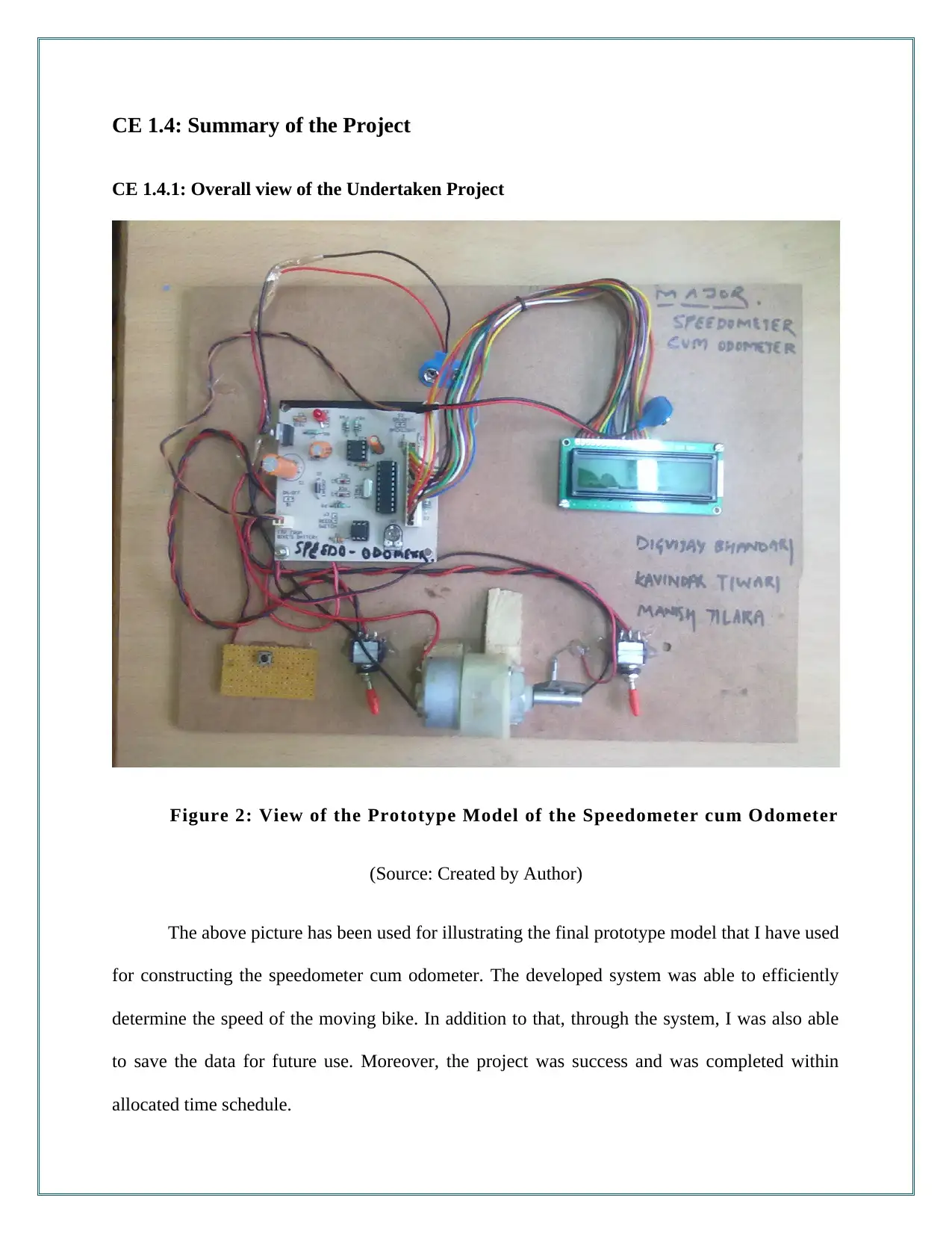
This report details the design and development of a digital speedometer and odometer project undertaken by a student. The project aimed to create a low-cost, reliable digital speedometer using a microcontroller, LCD display, and EEPROM for data storage. The report covers the project's background, aims, objectives, and the student's role in the design process, including circuit design, component selection, and the development of the logical flow chart. The student faced challenges with eddy current calculations, which were resolved by calibrating the return spring. The project utilized Keil Software and µVision3 IDE for programming and simulation. The report concludes with a summary of the project's success and the student's contributions. The report highlights the application of engineering skills and knowledge in areas such as circuit design, serial communication, and the use of various software tools for simulation and debugging. The project involved teamwork and communication with other students to achieve its goals. The final prototype model successfully determined the speed of a moving bike and saved data for future use.
Document Page
tabler-icon-diamond-filled.svg

Paraphrase This Document

Need a fresh take? Get an instant paraphrase of this document with our AI Paraphraser
Document Page
CE 1.1: Introduction to the Undertaken Project
Name of the Project : Design of Digital Speedometer cum Odometer
Geographical Location : [Please Fill]
Project Duration : [Please Fill]
Organization : [Please Fill]
Position in the Project : Team Member
CE 1.2: Background of the Project
CE 1.2.1: Features of the Undertaken Project
For any mobile transpiration, speed is considered as an essential parameter for
determining the movement quality. In traditional transport vehicles, analog meter are being used
for measuring the speed of the vehicle. I have observed the issue with the analog meter is in the
low resolution and lack of accuracy in measuring the speed of the vehicle. Therefore, in this
project, I have proposed for the design and development of digital speedometer cum odometer
with the use of microcontroller. I have proposed to use a microcontroller for controlling the
speedometer and LCD for displaying the speed to the user. Thorough the design of the
speedometer, I have proposed for providing an alternative and inexpensive digital speedometer
having resolution about 5 kmph and high range. In addition to that, I have used EEPROM for
saving the readings of the distance travelled for future use. I have used Philips I2C protocol and
24C02 serial standard for efficiently saving the data.
Document Page
CE 1.2.2: Aims and Objectives
In this project, I have developed my vital aim to propose an advanced design of
speedometer for digitally recording and showing the speed of the moving vehicle. In addition to
that I have aimed at designing a light weight and low cost design that would help in gaining
market popularity. For the effective completion I have developed the following objectives:
To evaluate and review the physical interaction, components and logical structure of
the speedometer;
To identify the low cost and high efficient hardware components for the speedometer;
To develop the prototype model and conduct the simulation process;
CE 1.2.3: Characteristic of my work in the Undertaken Project
During my work in this project, I was associated with the design of the I2C ad liquid
crystal display that I have attached with the speedometer. In addition to that, I have designed the
appropriate circuit diagram and designed the logical flow chart for checking the speed of the
moving vehicle. Moreover, I have developed and prepared the bike for practical examination of
the speedometer functionalities.
Document Page
CE 1.2.4: Organizational Structure Associated with this Project
Figure 1: Organizational structure Associated with the project
CE 1.2.5: My Duty Statement
Since, I have focused on developing reliable and cost-efficient model, I took the
responsibility of selecting the appropriate hardware module and interface for developing the
system. For the hardware device, I have selected the application of LCD unit, microcontroller,
oscillatory circuit, EEPRM unit, opto coupler and Magnetic sensors. On the other hand, for
developing the appropriate interface for the system, I have identified the integration of Sensor
interface, EEprom interface, Opt Coupler Interface and 16 x 2 LCD interface. I have further
developed the logical structure required for identifying the speed of the vehicle. For the selection
of the LCD module I have used HD44780 controller based 16x2 alphanumeric LCD with
backlight feature that allowed proper visualisation of the data at night.
tabler-icon-diamond-filled.svg

Paraphrase This Document

Need a fresh take? Get an instant paraphrase of this document with our AI Paraphraser
Document Page
CE 1.3: Distinctive Engineering Activity
CE 1.3.1: Theory and Vital Components of the Project
I have proposed on measuring the distance and speed of the moving vehicle. I have used
microcontroller for counting the interrupts in the vehicle. I have focused on demonstrating
different features including distance count, speed display, and digital readout for the
speedometer. I have focused on increasing the reliability of the speed detection for the
speedometer through this project. I have used Atmel AT89C2051 20 pin microcontroller due to
high compatibility and affordability with the 8051 family. I have developed the system for
detecting the speed digitally and display it on the LCD. In addition to that, for detecting the
speed of the vehicle, I have considered the use of Hero Honda’s Splendor model. I have focused
on determining the speed based on the front wheel of the bike. After measuring the wheel, I have
found the radius to be 30 cm. For evaluating the wheel’s circumference, I have used the formula
“circumference = 2πr” and obtained the circumference as 1.884 metres or 188.4 cm. For
calculating the speed I have assumed that the bike completes one revolution per second.
Therefore, I have defined the speed of the vehicle with the following formula:
“N×1.88×3600/1000 “. I have used N for denoting the number of revolutions take per second.
CE 1.3.2: Application of Appropriate Engineering Skills and Knowledge
While developing the logic converter, I have focused on designing the serial port for the
prototype model. I have designed the required serial port for establishing communication
between the computer and the microcontroller unit. In this project, since I was using a laptop, I
have used USB to serial convertor for ensuing communication. Through the application of the
serial port, I was able to communicate 8 bit at a time with the laptop. I have used pin number 2
Document Page
for receiving, pin number 3 for transmitting and pin number 5 as a ground pin. For the remaining
pin, I have used with modem for communication. For the serial transmission of data, I have
utilized RS-232 communication standard. With the use of RS-232 I was able to define the
voltage level in logical levels. Furthermore, I have used homemade speed transducer in this
project. I have fixed a magnet on the wheel and used reed switch for sensing the rotation of the
wheel. For detecting the speed, I have used speed sensor for providing the information about the
revolution directly to the microcontroller.
CE 1.3.3: Task Accomplishment and Delegation
I have printed the developed circuit design for the proposed speedometer. With the
application of the PBC, I was able to provide electrical and mechanical support to the hardware
component and laminating the non-conductive substrate. In this project, I have used OrCAD for
developing the core design ad schematic view of the circuit. For the development of the circuit
design, I have initially traced the design on butter paper and placed the paper on the film maker
along with the negative. For obtaining the design, I have used the AB solution for dipping the
negative and then with the fixer. In order to developing the appropriate film, I have dried the
negative and obtain the PBC board as the same size. I have used photo resist machine for resting
the PCB board. For printing the trace on the PBC board, I have used UV Exposer for 15 minutes.
After this, I have dried the board using the Etching Machine. For the integration of the hardware
elements, I have drilled the PCB and conducted various tests.
CE 1.3.4: Technical Problem and Difficulties Faced
Issue: I have used the concept and idea of eddy current in the speedometer. In this
project, I have initiated the speedometer mechanism after the motor cycle was in motion. I have
Document Page
further attached a small magnet along with aluminum cup with the cable for changing the shaft
of the analogue pointer. I have ensured that eddy current is produced when the magnet rotates
near the attacked cup. I have further used fine torsion spring for holding the pointer shaft at zero.
Due to the torsion sprint, I have observed that with the increment of the speed, the cup gets
twisted. I have faced significant technical issue when the increment of the bike speed has
resulted in errors in the speed calculation of the bike.
Solution: For resolving the issue with the eddy current, I have evaluated and studied the
developed architecture of the speedometer. From the analysis, I have observed that the speed of
the vehicle is directly proportional to the torque. On the other hand, the torque produced was
determining the direction of the deflection of the spring. In order to overcome with the problem,
I have calibrated the return spring in such a way that the integrated speedometer was responding
to the attached cable. In the calibration process, I have considered the final drive ratio, drive of
the flexible tires, and tail shaft gears in account.
CE 1.3.5: Creative Work Strategies
In order to provide creativeness in the project, I have utilized Keil Software for
integrating the appropriate environment for the developed prototype model of the speedometer.
Through the use of Keil Software, I have programmed the microcontroller with C programming
language and conducted simulation for ensuring proper functionality and operation of proposed
speedometer. I have further utilized my knowledge about μVision3 IDE for writing, compiling
and debugging the program on the embedded system. With the application of μVision3, I was
able to encapsulate the functionalities of debugger, editor, tool configuration, while managing
the operation of the system. For the development of the program, I have used Micro Vision and
created a new project for the speedometer under the existing directory. In the laboratory, I have
tabler-icon-diamond-filled.svg

Paraphrase This Document

Need a fresh take? Get an instant paraphrase of this document with our AI Paraphraser
Document Page
used AT89S52 chip name for simulating the proposed system. I have further created the
program, in a HEX file that provided me with easy integration in the selected microcontroller
unit for the prototype model. During the simulation process, I have found several errors during
the compilation time. I have used the column number for easily locating the errors in the
program. After successfully compiling the program I have used Keil Micro Vision for simulating
the developed logic for the microcontroller. With the application of Keil Vision, I was able to
reduce the chances of error and failure of the codes in the microcontroller.
CE 1.3.6: Team Work Done
I was working in this project along with three other students for the completion of the
speedometer design. I have thoroughly discussed the design and implementation plan before
proceeding with the prototype. Moreover, I have followed communication and responsibility
assessment matrix for ensuring the proper flow of information.
Document Page
CE 1.4: Summary of the Project
CE 1.4.1: Overall view of the Undertaken Project
Figure 2: View of the Prototype Model of the Speedometer cum Odometer
(Source: Created by Author)
The above picture has been used for illustrating the final prototype model that I have used
for constructing the speedometer cum odometer. The developed system was able to efficiently
determine the speed of the moving bike. In addition to that, through the system, I was also able
to save the data for future use. Moreover, the project was success and was completed within
allocated time schedule.
Document Page
CE 1.4.2: My Personal Contribution to Project Activities
Throughout the project, I have used my theoretical and conceptual knowledge and
information about the circuit design and other hardware components that I have used for
speedometer. I have suggested the updating the odometer after each 100 meters for saving the
speed data frequently.
chevron_up_icon
1 out of 10
circle_padding
hide_on_mobile
zoom_out_icon
[object Object]