Analysis and Design of Discrete Root Locus and PID Controller Systems
VerifiedAdded on 2022/12/26
|19
|2810
|55
Project
AI Summary
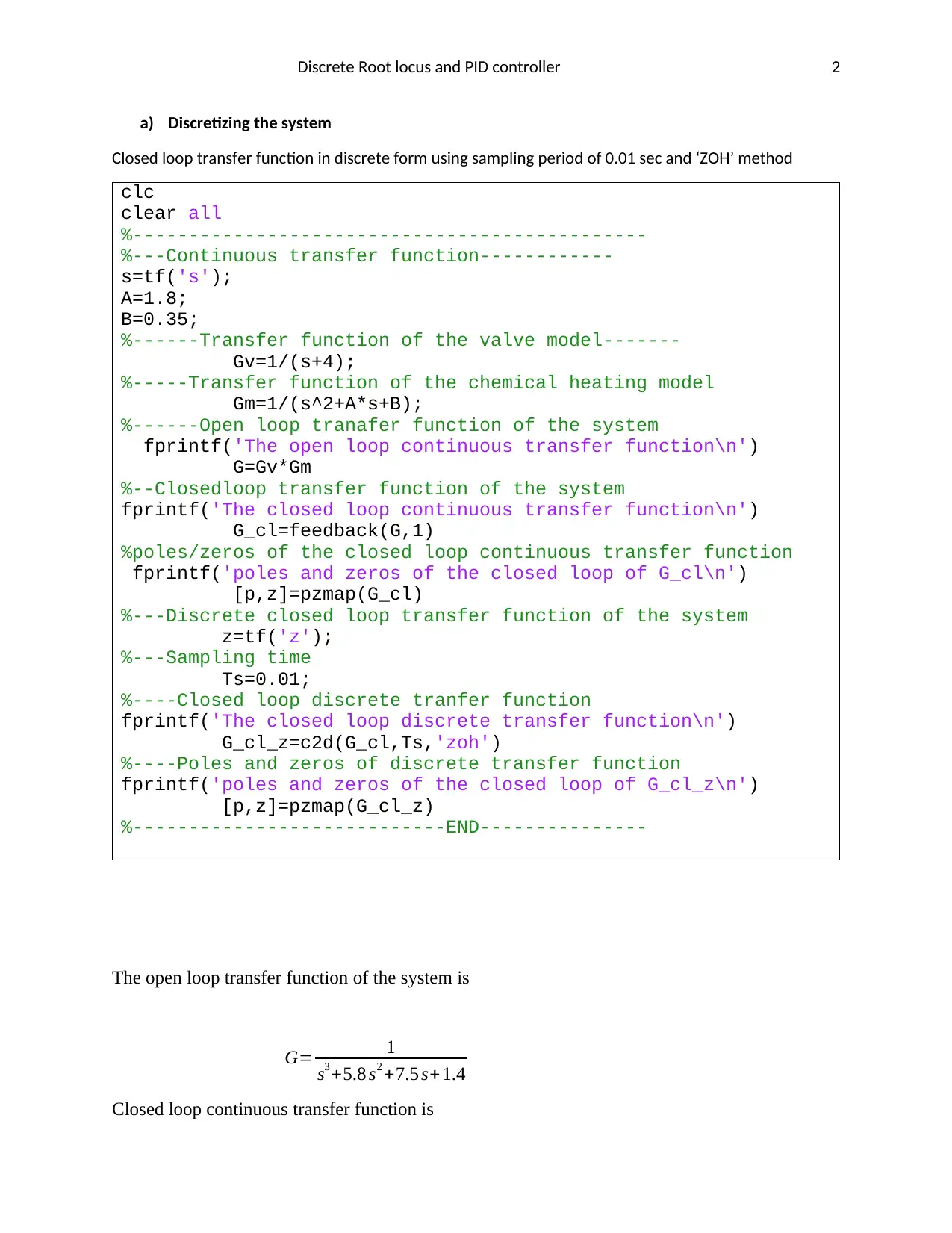
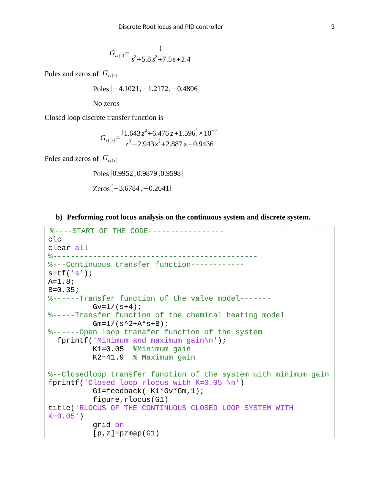
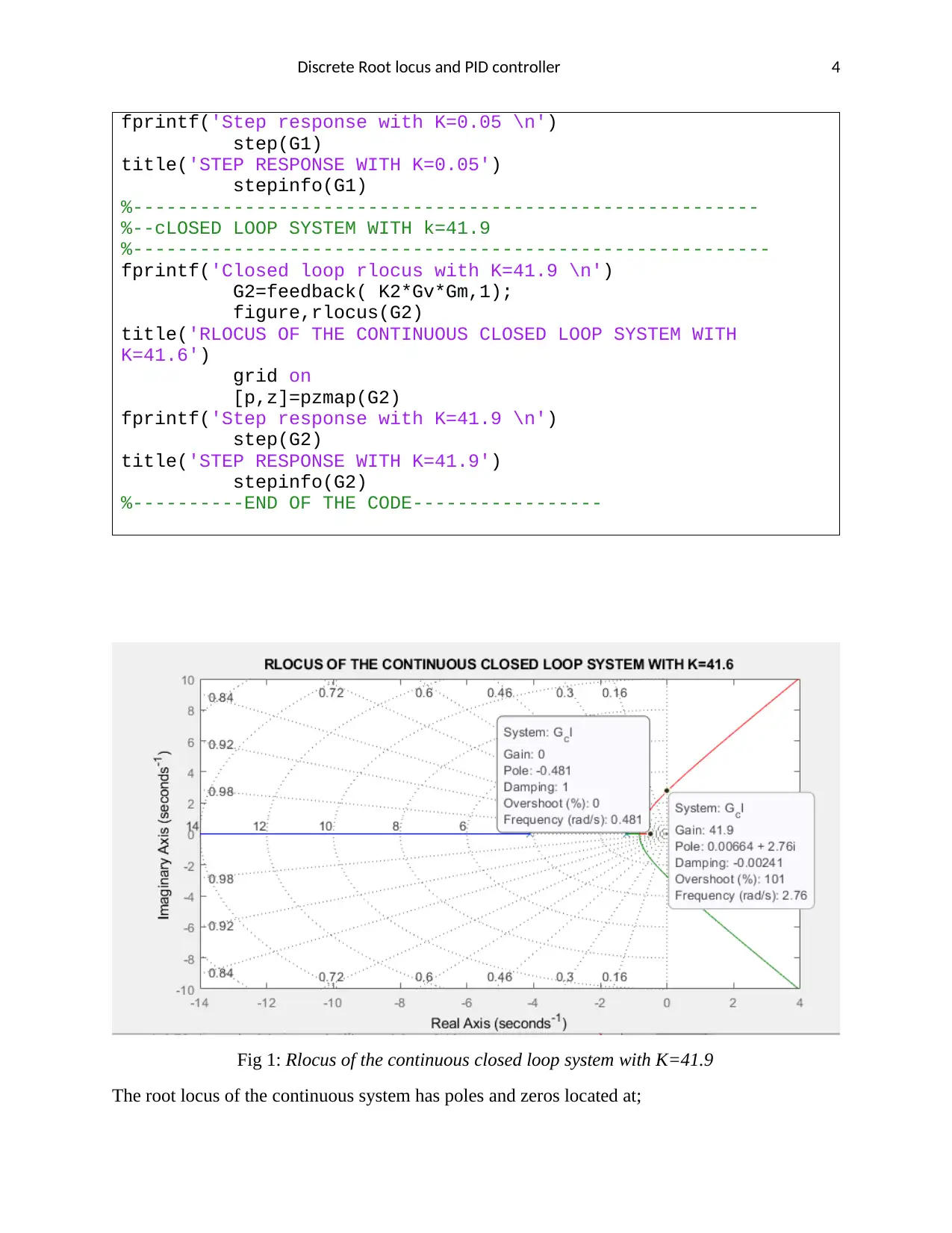
This project delves into the analysis and design of a control system, focusing on discrete root locus and PID controller implementation. The project begins by discretizing a continuous-time transfer function using the zero-order hold (ZOH) method and then analyzes the system's behavior using root locus plots in both continuous and discrete domains. The impact of different sampling frequencies on system stability and gain bandwidth is investigated. The project then proceeds to design a discrete PID compensator, implemented using Matlab Simulink, to improve the system's performance. The analysis includes the effects of the PID controller on the root locus, and the step responses of both the uncompensated and compensated systems are compared to assess the improvements in steady-state error and transient response. The findings highlight the importance of stability analysis in both continuous and discrete time domains, the effects of sampling frequency, and the benefits of PID compensation in enhancing system performance. The project concludes with references to relevant sources.

Discrete Root locus and PID controller 1
Student
Professor
Control System
Date
Student
Professor
Control System
Date
Secure Best Marks with AI Grader
Need help grading? Try our AI Grader for instant feedback on your assignments.

Discrete Root locus and PID controller 2
a) Discretizing the system
Closed loop transfer function in discrete form using sampling period of 0.01 sec and ‘ZOH’ method
clc
clear all
%----------------------------------------------
%---Continuous transfer function------------
s=tf('s');
A=1.8;
B=0.35;
%------Transfer function of the valve model-------
Gv=1/(s+4);
%-----Transfer function of the chemical heating model
Gm=1/(s^2+A*s+B);
%------Open loop tranafer function of the system
fprintf('The open loop continuous transfer function\n')
G=Gv*Gm
%--Closedloop transfer function of the system
fprintf('The closed loop continuous transfer function\n')
G_cl=feedback(G,1)
%poles/zeros of the closed loop continuous transfer function
fprintf('poles and zeros of the closed loop of G_cl\n')
[p,z]=pzmap(G_cl)
%---Discrete closed loop transfer function of the system
z=tf('z');
%---Sampling time
Ts=0.01;
%----Closed loop discrete tranfer function
fprintf('The closed loop discrete transfer function\n')
G_cl_z=c2d(G_cl,Ts,'zoh')
%----Poles and zeros of discrete transfer function
fprintf('poles and zeros of the closed loop of G_cl_z\n')
[p,z]=pzmap(G_cl_z)
%----------------------------END---------------
The open loop transfer function of the system is
G= 1
s3 +5.8 s2 +7.5 s+ 1.4
Closed loop continuous transfer function is

Discrete Root locus and PID controller 3
Gcl (s)= 1
s3 +5.8 s2 +7.5 s +2.4
Poles and zeros of Gcl (s)
Poles (−4.1021,−1.2172,−0.4806 )
No zeros
Closed loop discrete transfer function is
Gcl (z )= (1.643 z2 +6.476 z +1.596 ) ×10−7
z3 −2.943 z2 +2.887 z−0.9436
Poles and zeros of Gcl (z )
Poles ( 0.9952 , 0.9879 ,0.9598 )
Zeros ( −3.6784 ,−0.2641 )
b) Performing root locus analysis on the continuous system and discrete system.
%----START OF THE CODE-----------------
clc
clear all
%----------------------------------------------
%---Continuous transfer function------------
s=tf('s');
A=1.8;
B=0.35;
%------Transfer function of the valve model-------
Gv=1/(s+4);
%-----Transfer function of the chemical heating model
Gm=1/(s^2+A*s+B);
%------Open loop tranafer function of the system
fprintf('Minimum and maximum gain\n');
K1=0.05 %Minimum gain
K2=41.9 % Maximum gain
%--Closedloop transfer function of the system with minimum gain
fprintf('Closed loop rlocus with K=0.05 \n')
G1=feedback( K1*Gv*Gm,1);
figure,rlocus(G1)
title('RLOCUS OF THE CONTINUOUS CLOSED LOOP SYSTEM WITH
K=0.05')
grid on
[p,z]=pzmap(G1)

Discrete Root locus and PID controller 4
fprintf('Step response with K=0.05 \n')
step(G1)
title('STEP RESPONSE WITH K=0.05')
stepinfo(G1)
%--------------------------------------------------------
%--cLOSED LOOP SYSTEM WITH k=41.9
%---------------------------------------------------------
fprintf('Closed loop rlocus with K=41.9 \n')
G2=feedback( K2*Gv*Gm,1);
figure,rlocus(G2)
title('RLOCUS OF THE CONTINUOUS CLOSED LOOP SYSTEM WITH
K=41.6')
grid on
[p,z]=pzmap(G2)
fprintf('Step response with K=41.9 \n')
step(G2)
title('STEP RESPONSE WITH K=41.9')
stepinfo(G2)
%----------END OF THE CODE-----------------
Fig 1: Rlocus of the continuous closed loop system with K=41.9
The root locus of the continuous system has poles and zeros located at;
Secure Best Marks with AI Grader
Need help grading? Try our AI Grader for instant feedback on your assignments.

Discrete Root locus and PID controller 5
Poles ( n )={−4.1021,−1.2172,−0.4806 }
There are no zeros , Zeros ( n ) =¿
The total number of asymptotes from the diagram above is 3.
A=3
Theoretically, total number of asymptotes is calculated using total number of poles and zeros as
shown in the formula below.
A=n−m→3−0=3
Angles of asymptotes are
q0=60
q1=300
q2=180
Centroid of asymptotes from the plot is approximately
Centroid ≈−2
Theoretically, centroid is calculated as
Centroid= ∑ n−∑ m
n−m = ( −4.1021−1.2172−0.4806 )
3 =−1.933
For stability with varying gain, the minimum and maximum value of gain (K) is as shown from
the figure below.

Discrete Root locus and PID controller 6
Fig 2: Rlocus of the continuous closed loop system with k=0.05
From fig 2, it can be deduced that the minimum value of gain K should be greater than zero.
K >0
When K=0.05, then poles and zeros of the closed loop continuous system are located at
Poles ( n ) ={−4.0054 ,−1.5626 ,−0.2316 }
There are no zeros , Zeros ( n ) =¿
The closed loop system has real poles located to the LHP(Left Hand Plane). This denotes that
stability of the system is stable. On addition, step response of the closed loop system is non-
oscillatory since all poles are real. The step response of the system with K=0.05 is as shown
below.

Discrete Root locus and PID controller 7
Fig 3: Step response of the continuous closed loop system with K=0.05
However, steady state error of the system to step response is so large since the system
stabilizes at 0.035.
ss=1−0.035
1 ×100 %=96.5 %
Where ss is the steady state error.
The maximum gain K was determined by shifting position of the pole along the asymptote 600
as shown in fig 1. The maximum gain was approximately found to be;
K=41.9
The closed loop root locus of the continuous transfer function with estimated maximum value
of K=41.9 is as shown in the figure below.
Paraphrase This Document
Need a fresh take? Get an instant paraphrase of this document with our AI Paraphraser

Discrete Root locus and PID controller 8
Fig 4: Rlocus of the continuous closed loop system with K=41.9
The system has poles and zeros located at;
Poles ( n )= { −5.7881
−0.006− j 2.7351
−0.006+ j2.7351
There are no zeros , Zeros ( n ) =¿
Existence of complex poles introduces oscillatory transient response that stabilizes after some
time. The step response of the system at maximum gain is as shown below.

Discrete Root locus and PID controller 9
Fig 5: Step response of the continuous closed loop system with K=41.9
The system, as previously described, oscillates with percentage overshoot greater than 100%.
However, with higher gain, the steady state error has been tremendously reduced to zero.
Therefore, low gain reduces percentage overshoot but increases the steady state error while
higher gain reduces steady state error but introduced oscillations in the step response.
The closed loop transfer function was discretized using ‘Zero Order Hold’ (ZOH) method at
various sampling time represented by ( 10 Hz , 100 Hz∧500 Hz ) respectively as in the Matlab
script below.
%------START OF THE CODE--------------
clc
clear all
%----------------------------------------------
%---Continuous transfer function------------
s=tf('s');
A=1.8;
B=0.35;
%------Transfer function of the valve model-------
Gv=1/(s+4);
%-----Transfer function of the chemical heating model
Gm=1/(s^2+A*s+B);
%--Closedloop transfer function of the system with minimum gain
fprintf('Closed loop transfer function\n')

Discrete Root locus and PID controller 10
Gs=feedback(Gv*Gm,1);
%---Discrete closed loop transfer function of the system
z=tf('z');
%---Sampling times conversted from frequencies----
Ts1=1/10; % 10Hz
Ts2=1/100; %100Hz
Ts3=1/500; %500Hz
%----Closed loop discrete tranfer function--------
fprintf('The closed loop discrete transfer functions\n');
%----Transfer at 10Hz-----------------------------
Gz1=c2d(Gs,Ts1,'zoh')
figure,rlocus(Gz1)
title('RLOCUS AT T=10Hz')
[p,z]=pzmap(Gz1)
%----Transfer at 100Hz-----------------------------
Gz2=c2d(Gs,Ts2,'zoh')
figure,rlocus(Gz2)
title('RLOCUS AT T=100Hz')
[p,z]=pzmap(Gz2)
%----Transfer at 500Hz-----------------------------
Gz3=c2d(Gs,Ts3,'zoh')
figure,rlocus(Gz3)
title('RLOCUS AT T=500Hz')
[p,z]=pzmap(Gz3)
%------------END------------------
The results obtained when the above code was executed are;
At sampling time of 10Hz
The discrete closed loop transfer function of the system is as shown below.
G z1 =0.0001445 z2+ 0.0005014 z+0.0001082
z3−2.502 z2 +2.064 z −0.5599
The root locus of the system is as shown below.
Secure Best Marks with AI Grader
Need help grading? Try our AI Grader for instant feedback on your assignments.

Discrete Root locus and PID controller 11
Fig 7: Rlocus of discrete closed loop system with 10Hz sampling frequency.
Poles and zeros of the discrete system are;
Poles ( n ) = {
0.9531
0.8854
0.6635
Zeros ( m ) = {−3.2379
−0.2311
At sampling time of 100Hz
The discrete closed loop transfer function of the system is as shown below.
G z1 =(1.643 z2 +6.476 z +1.596)× 10−7
z3 −2.943 z2 +2.887 z−0.9436
The root locus of the system is as shown below.

Discrete Root locus and PID controller 12
Fig 8: Rlocus of discrete closed loop system with 100Hz sampling frequency.
Poles and zeros of the discrete system are;
Poles ( n ) = {
0.9952
0.9879
0.9598
Zeros ( m ) = {−3.6784
−0.2641
At sampling time of 500Hz
The discrete closed loop transfer function of the system is as shown below.
G z1 =(1.329 z2 +5.303 z+ 1.322)×10−9
z3−2.988 z2 +2.977 z−0.9886
The root locus of the system is as shown below.

Discrete Root locus and PID controller 13
Fig 9: Rlocus of discrete closed loop system with 500Hz sampling frequency.
Poles and zeros of the discrete system are;
Poles ( n ) = {
0.9976
0.9990
0.9918
Zeros ( m ) = {−3.7212
−0.2672
The stability of closed loop discrete system is guaranteed when poles of the discrete transfer
function falls with a unit circle restrained by ( (1,0)|(−1,0) ) on the complex Cartesian plane.
From the observation, as the frequency increases, poles of the discrete closed loop transfer
function shifts towards critical boundary of the unity circle. The poles under influence of 500Hz
are approximately lying along the unit circle as compared to the poles under influence of 10Hz.
In terms of gain bandwidth, the system with higher sampling frequency allows higher allowable
system gain as compared to systems with lower sampling frequency (Nptel.ac.in, 2019)
c) Designing a discrete PID compensator
Applying the PID compensation for the digital system.
Paraphrase This Document
Need a fresh take? Get an instant paraphrase of this document with our AI Paraphraser

Discrete Root locus and PID controller 14
Open loop time continuous transfer functions were digitalized using Tustin or Bilinear method so
as to best frequency correlation between digitalized and time continuous system.
Matlab Script code
%------START OF THE CODE--------------
clc
clear all
%----------------------------------------------
%---Continuous transfer function------------
s=tf('s');
A=1.8;
B=0.35;
%------Transfer function of the valve model-------
Gv=1/(s+4);
%-----Transfer function of the chemical heating model
Gm=1/(s^2+A*s+B);
%---Discrete closed loop transfer function of the system
z=tf('z');
%---Sampling times conversted from frequencies----
Ts=0.01;
%----Closed loop discrete tranfer function--------
fprintf('The Open loop discrete transfer using Tustin method
function\n')
Gz1=c2d(Gm,Ts,'tustin')
Gz2=c2d(Gv,Ts,'tustin')
%----------------------------------------------------
%-----THE PID CONTROLLER WAS MODELLED IN MATLAB SIMULINK----
%---------------------------------------------------------
%----PID controller modelled
P=15.3426; % Proportional controller
I=10.1418; % Integral controller
D=5.7289; % Derivative controller
N=103.464; % Filter coefficient
fprintf('Tuned PID controller\n')
PID=P+I*Ts*1/(z-1)+D*N/(1+Ts*N/(z-1))
%-----------------------------------------------------
%-----Plotting rlocus of uncompensated discrete closed loop T.F
Gz1=feedback(Gz1*Gz2,1)
figure,rlocus(Gz1)
title('Rlocus of uncompensated Closed Loop')
fprintf('Poles and Zeros of Uncompensated system\n')
[p,z]=pzmap(Gz1)
%-----Plotting rlocus of pid compensated discrete closed loop
%---T.F
Gz=feedback(Gz1*Gz2*PID,1)
figure,rlocus(Gz)

Discrete Root locus and PID controller 15
title('Rlocus of Closed Loop PID compensated')
fprintf('Poles and Zeros of compensated system\n')
[p,z]=pzmap(Gz)
%------Plotting step responses of the system
figure,step(Gz1,Gz)
legend('Uncompensated','Compensated')
title('Step Response of Compensated & uncompensated')
%------END OF THE CODE
The digital PID compensator was designed in Matlab Simulink.
Fig 10. PID tuning in Matlab Simulink
Fig 11. Discrete Closed Loop system in Matlab Simulink 2019
Tuned PID controller is as shown below

Discrete Root locus and PID controller 16
PID=P+ I T s ( 1
z −1 )+D N
1+ N T s
1
Z −1
Where
P=15.3426, I =10.1414, D=5.7289
N=103.464 (filter coefficient ),
Running the Matlab Code, PID controller is simplified to;
PID= 608.1 z2 −1200 z +592.2
z2−0.9654 z−0.03464
Fig 12. Rlocus of uncompensated discrete closed loop system
Poles {
0.9952
0.9879
0.9598
zeros {−1
−1
−1
Secure Best Marks with AI Grader
Need help grading? Try our AI Grader for instant feedback on your assignments.

Discrete Root locus and PID controller 17
Fig 13. Rlocus of PID compensated discrete closed loop system
Poles {
0.9969+ j 0.0068 ,
0.9969+ j 0.0068
0.9878 ,
, ,
0.9710
−0.9510
−0.0346
zeros { 0.9969+ j 0.0001 ,
0.9969+ j 0.0001
−1.0001+ j 0.0001 ,
, ,
−1.0001− j 0.0001
−0.9999+ j 0.0001
−0.9999− j 0.0001
It has been notably seen that the controller adds extra poles and zeros on the closed loop discrete
system. In both compensated and uncompensated system, poles are located within the unit circle
((1,0), (-1,0)) insinuating that both systems have elements of stability. For the uncompensated
system, all poles are real. The implication of real poles indicates that the step response of the
uncompensated system is non-oscillatory as shown in fig 14. However, the steady state error of
the uncompensated system is so huge. On contrary, PID compensated system as from fig 13 has
got 6 poles with some of them being complex. Complex poles result to oscillatory step response
before settling time. However, the steady state error of the compensated system has been greatly
reduced as evidenced in fig 14. From fig 13, a pole located at (-0.0346) is influential on the range
of gain of the system. Higher gain bandwidth enabled the compensated system to settle at an
amplitude of 1 as expected.

Discrete Root locus and PID controller 18
Fig 14. Step Response of Uncompensated and compensated discrete closed loop system.
Conclusion
Stability of the open and closed loop has been analyzed using root locus in continuous time
domain environment and discrete time domain environment. In time domain, and with regard
to root locus, stability of the system is established when all poles are negative. The maximum
range of gain was also determined making sure no pole crosses over to the positive plane (Right
hand plane). In digital environment, stability of the system using root locus is guaranteed when
all poles fall within the unit circle bounded by ( (1,0)|(−1,0) ). Also effects of sampling frequency
on gain bandwidth was also observed. The system stability response was better with higher
sampling frequency. The discrete closed loop system was compensated using PID controller
designed in Matlab Simulink. It was seen how compensator improves steady state response of
the system by adding extra poles and zeros to the system.

Discrete Root locus and PID controller 19
References.
Nptel.ac.in. (2019). NPTEL :: Electrical Engineering - Digital Control System. [online] Available at:
https://nptel.ac.in/courses/108103008/14 [Accessed 17 Jun. 2019].
References.
Nptel.ac.in. (2019). NPTEL :: Electrical Engineering - Digital Control System. [online] Available at:
https://nptel.ac.in/courses/108103008/14 [Accessed 17 Jun. 2019].
1 out of 19
Related Documents

Your All-in-One AI-Powered Toolkit for Academic Success.
+13062052269
info@desklib.com
Available 24*7 on WhatsApp / Email
Unlock your academic potential
© 2024 | Zucol Services PVT LTD | All rights reserved.