System Analysis and Design Report: Doc Medical Centre Website Project
VerifiedAdded on 2023/01/07
|19
|3240
|28
Report
AI Summary
This report presents a system analysis and design for the Doc Medical Centre, focusing on a user-friendly website for patients. The report includes detailed use case descriptions for account registration and appointment booking, along with corresponding use case diagrams. It identifies entities and attributes, constructing an Entity-Relationship (ER) diagram to illustrate database relationships. Furthermore, the report incorporates class, sequence, and activity diagrams to depict system structure and behavior. The design of data entry screens for personal information and appointment booking is also addressed. The report concludes with a testing plan and deployment activities, providing a comprehensive overview of the system's development and implementation. The report is designed to provide a clear understanding of the system's functionalities and the flow of information within the medical system.

SYSTEM ANALYSIS AND DESIGN
1
1
Paraphrase This Document
Need a fresh take? Get an instant paraphrase of this document with our AI Paraphraser
Contents
INTRODUCTION...........................................................................................................................3
TASK...............................................................................................................................................3
Use Case description for making an appointment, registering accounts.....................................3
Use Case diagram........................................................................................................................6
Identifying all entities and their attribute, create E-R relationship diagram................................7
Class Diagram............................................................................................................................10
Sequence diagram......................................................................................................................11
Activity diagram........................................................................................................................12
Design the data entry screen for enter personal information or data.........................................13
Design booking appointment input screen, which mainly include patient id, name, selected GP
and visit......................................................................................................................................15
Make a suitable testing plan and deployment activities............................................................16
CONCLUSION..............................................................................................................................17
REFERENCES..............................................................................................................................18
2
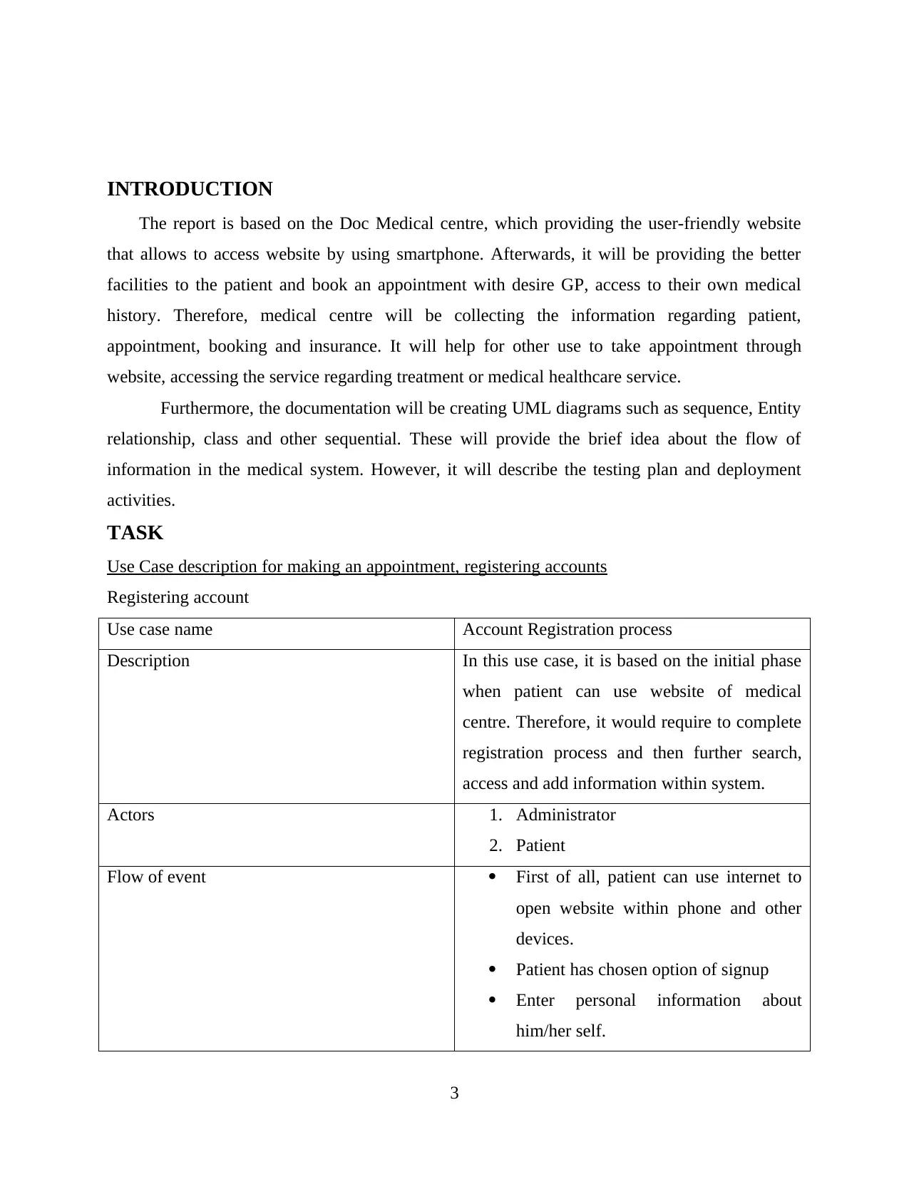
INTRODUCTION
The report is based on the Doc Medical centre, which providing the user-friendly website
that allows to access website by using smartphone. Afterwards, it will be providing the better
facilities to the patient and book an appointment with desire GP, access to their own medical
history. Therefore, medical centre will be collecting the information regarding patient,
appointment, booking and insurance. It will help for other use to take appointment through
website, accessing the service regarding treatment or medical healthcare service.
Furthermore, the documentation will be creating UML diagrams such as sequence, Entity
relationship, class and other sequential. These will provide the brief idea about the flow of
information in the medical system. However, it will describe the testing plan and deployment
activities.
TASK
Use Case description for making an appointment, registering accounts
Registering account
Use case name Account Registration process
Description In this use case, it is based on the initial phase
when patient can use website of medical
centre. Therefore, it would require to complete
registration process and then further search,
access and add information within system.
Actors 1. Administrator
2. Patient
Flow of event First of all, patient can use internet to
open website within phone and other
devices.
Patient has chosen option of signup
Enter personal information about
him/her self.
3
⊘ This is a preview!⊘
Do you want full access?
Subscribe today to unlock all pages.
Trusted by 1+ million students worldwide
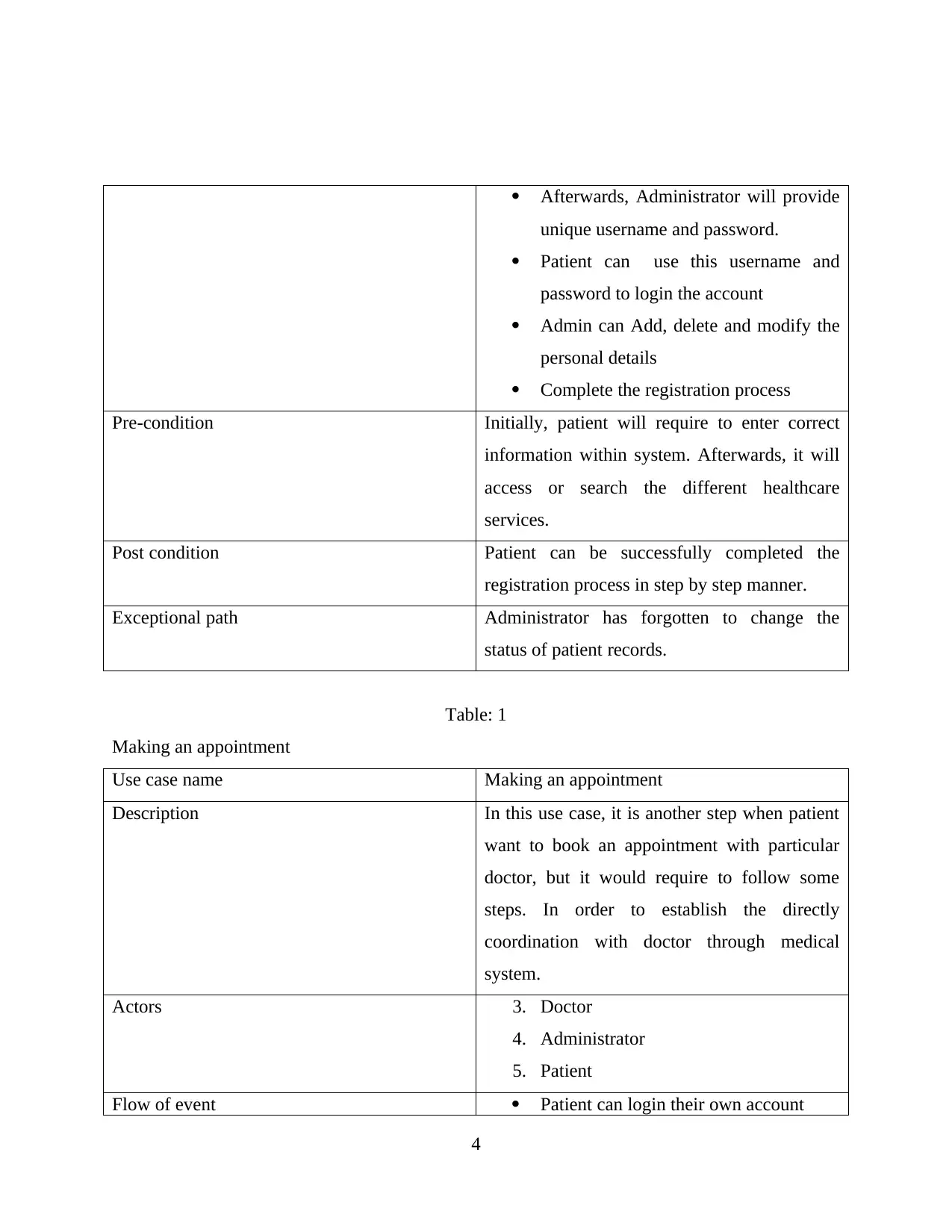
Afterwards, Administrator will provide
unique username and password.
Patient can use this username and
password to login the account
Admin can Add, delete and modify the
personal details
Complete the registration process
Pre-condition Initially, patient will require to enter correct
information within system. Afterwards, it will
access or search the different healthcare
services.
Post condition Patient can be successfully completed the
registration process in step by step manner.
Exceptional path Administrator has forgotten to change the
status of patient records.
Table: 1
Making an appointment
Use case name Making an appointment
Description In this use case, it is another step when patient
want to book an appointment with particular
doctor, but it would require to follow some
steps. In order to establish the directly
coordination with doctor through medical
system.
Actors 3. Doctor
4. Administrator
5. Patient
Flow of event Patient can login their own account
4
Paraphrase This Document
Need a fresh take? Get an instant paraphrase of this document with our AI Paraphraser
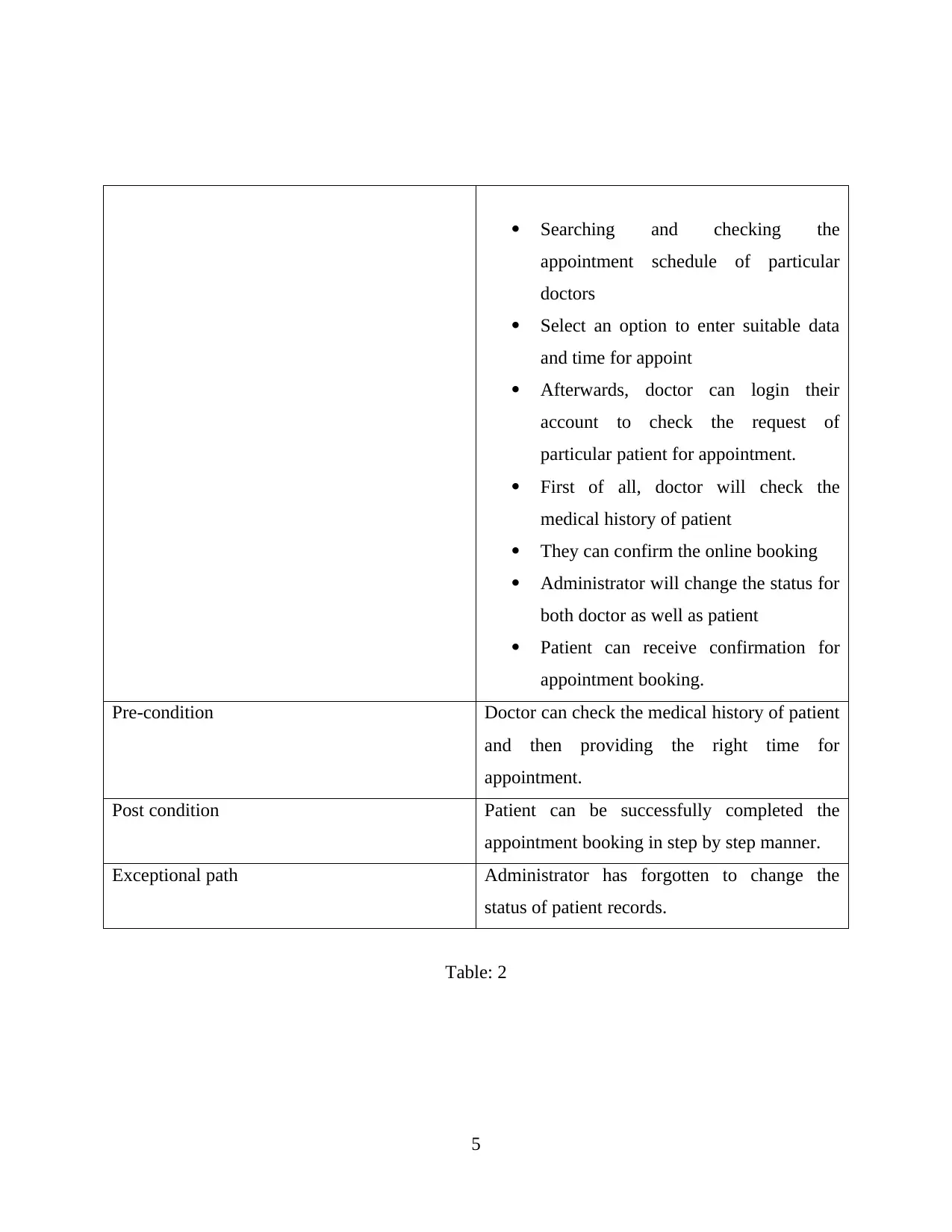
Searching and checking the
appointment schedule of particular
doctors
Select an option to enter suitable data
and time for appoint
Afterwards, doctor can login their
account to check the request of
particular patient for appointment.
First of all, doctor will check the
medical history of patient
They can confirm the online booking
Administrator will change the status for
both doctor as well as patient
Patient can receive confirmation for
appointment booking.
Pre-condition Doctor can check the medical history of patient
and then providing the right time for
appointment.
Post condition Patient can be successfully completed the
appointment booking in step by step manner.
Exceptional path Administrator has forgotten to change the
status of patient records.
Table: 2
5
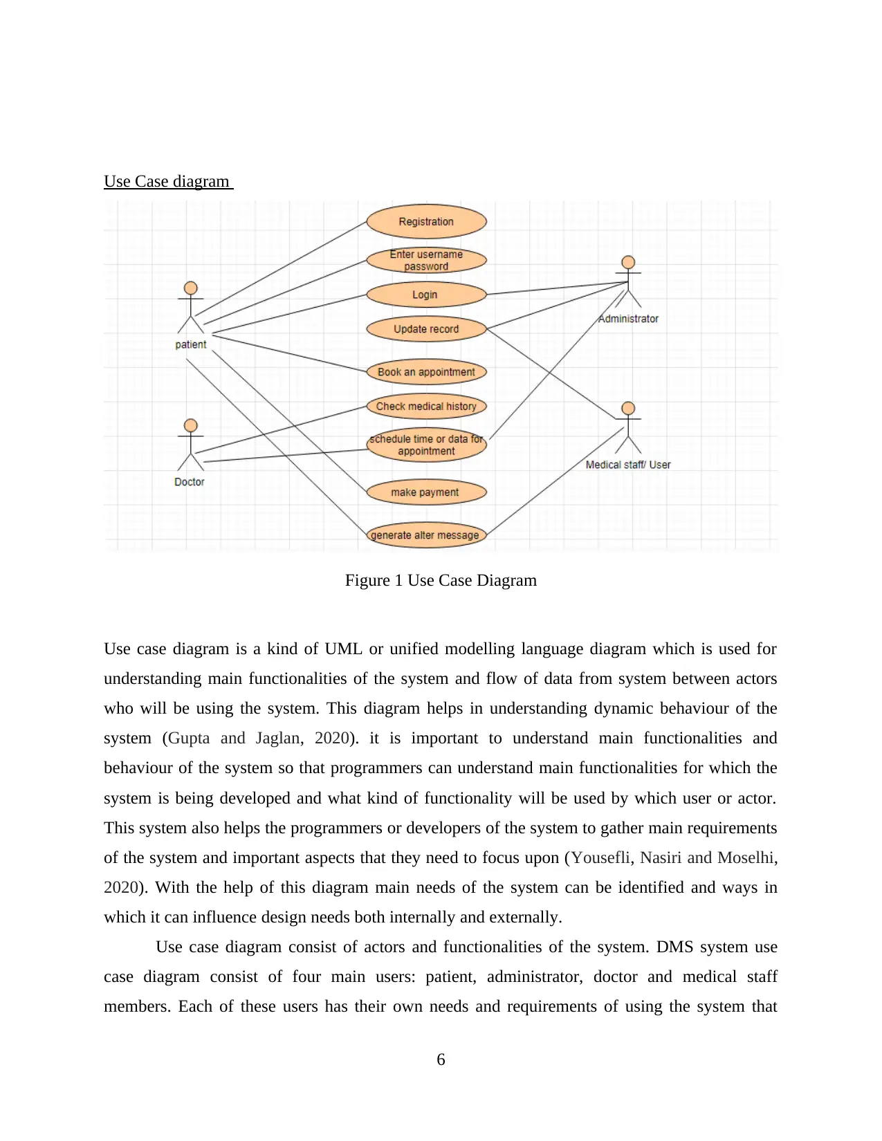
Use Case diagram
Figure 1 Use Case Diagram
Use case diagram is a kind of UML or unified modelling language diagram which is used for
understanding main functionalities of the system and flow of data from system between actors
who will be using the system. This diagram helps in understanding dynamic behaviour of the
system (Gupta and Jaglan, 2020). it is important to understand main functionalities and
behaviour of the system so that programmers can understand main functionalities for which the
system is being developed and what kind of functionality will be used by which user or actor.
This system also helps the programmers or developers of the system to gather main requirements
of the system and important aspects that they need to focus upon (Yousefli, Nasiri and Moselhi,
2020). With the help of this diagram main needs of the system can be identified and ways in
which it can influence design needs both internally and externally.
Use case diagram consist of actors and functionalities of the system. DMS system use
case diagram consist of four main users: patient, administrator, doctor and medical staff
members. Each of these users has their own needs and requirements of using the system that
6
⊘ This is a preview!⊘
Do you want full access?
Subscribe today to unlock all pages.
Trusted by 1+ million students worldwide
have been explained with the help of nine main functionalities of system that are: login,
registration, update records, appointment booking, checking medical history, scheduling
appointment date and time, making payment, generation of after message, consultation. Each of
these functionalities are used by different users in order to interact with the system such as:
registration is done by patients so that they can book an appointment with doctors. Records can
be updated by either administrator or medical staff members.
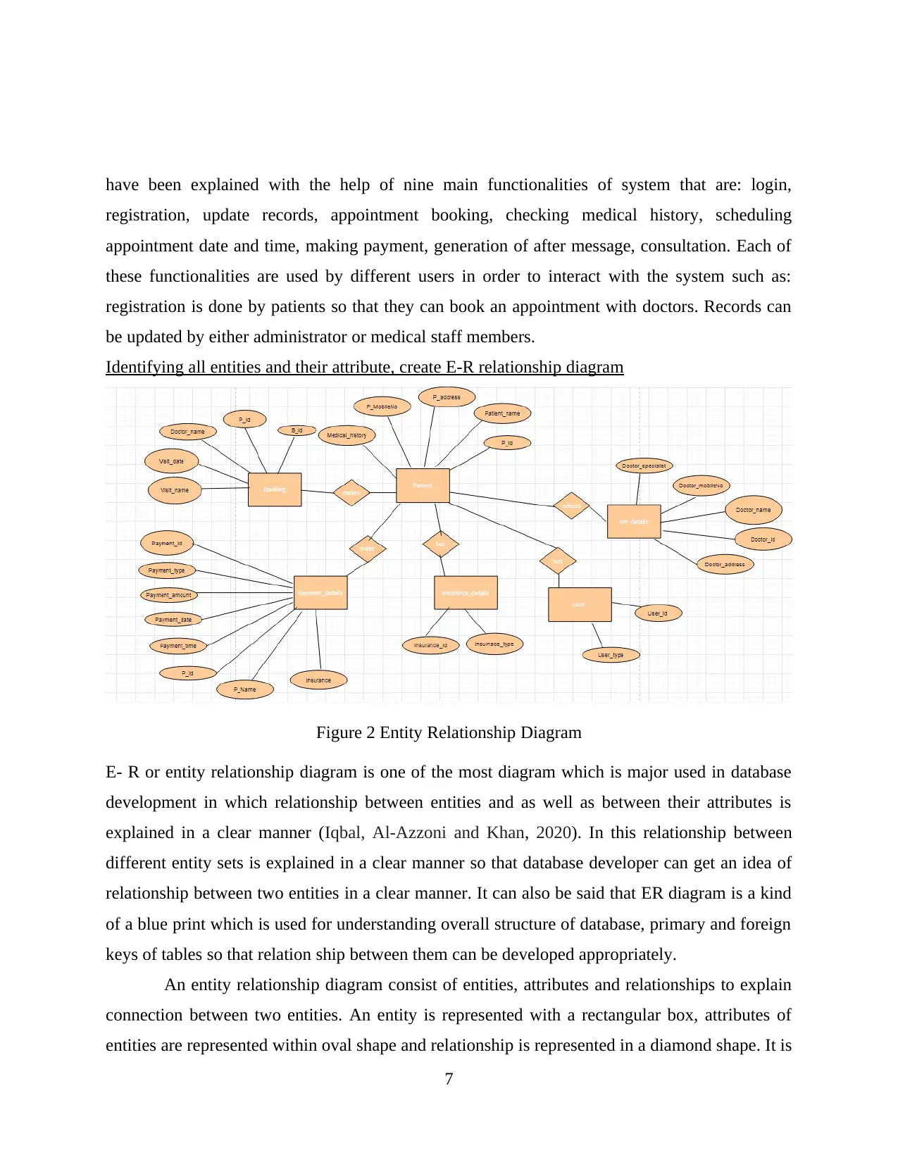
Identifying all entities and their attribute, create E-R relationship diagram
Figure 2 Entity Relationship Diagram
E- R or entity relationship diagram is one of the most diagram which is major used in database
development in which relationship between entities and as well as between their attributes is
explained in a clear manner (Iqbal, Al-Azzoni and Khan, 2020). In this relationship between
different entity sets is explained in a clear manner so that database developer can get an idea of
relationship between two entities in a clear manner. It can also be said that ER diagram is a kind
of a blue print which is used for understanding overall structure of database, primary and foreign
keys of tables so that relation ship between them can be developed appropriately.
An entity relationship diagram consist of entities, attributes and relationships to explain
connection between two entities. An entity is represented with a rectangular box, attributes of
entities are represented within oval shape and relationship is represented in a diamond shape. It is
7
registration, update records, appointment booking, checking medical history, scheduling
appointment date and time, making payment, generation of after message, consultation. Each of
these functionalities are used by different users in order to interact with the system such as:
registration is done by patients so that they can book an appointment with doctors. Records can
be updated by either administrator or medical staff members.
Identifying all entities and their attribute, create E-R relationship diagram
Figure 2 Entity Relationship Diagram
E- R or entity relationship diagram is one of the most diagram which is major used in database
development in which relationship between entities and as well as between their attributes is
explained in a clear manner (Iqbal, Al-Azzoni and Khan, 2020). In this relationship between
different entity sets is explained in a clear manner so that database developer can get an idea of
relationship between two entities in a clear manner. It can also be said that ER diagram is a kind
of a blue print which is used for understanding overall structure of database, primary and foreign
keys of tables so that relation ship between them can be developed appropriately.
An entity relationship diagram consist of entities, attributes and relationships to explain
connection between two entities. An entity is represented with a rectangular box, attributes of
entities are represented within oval shape and relationship is represented in a diamond shape. It is
7
Paraphrase This Document
Need a fresh take? Get an instant paraphrase of this document with our AI Paraphraser
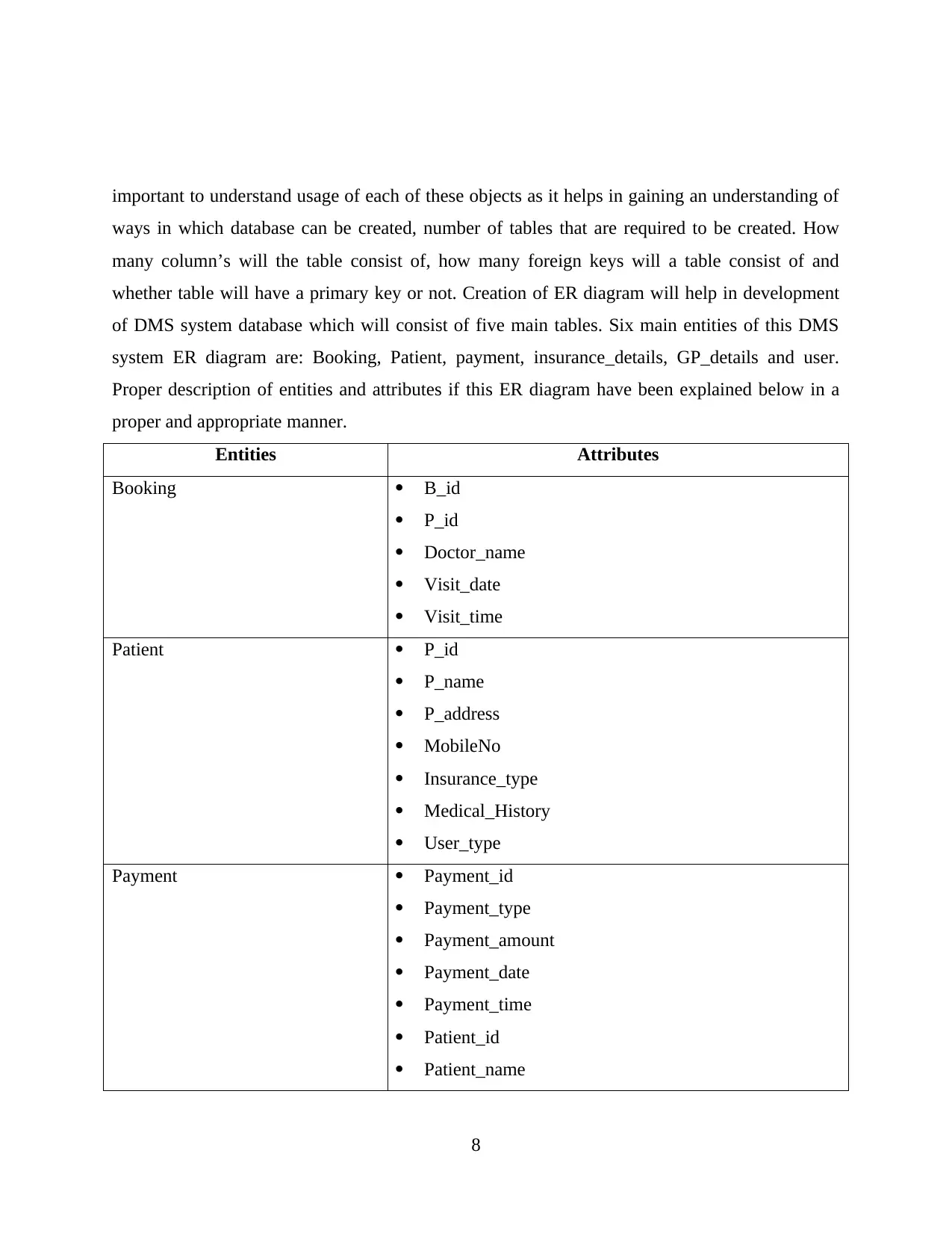
important to understand usage of each of these objects as it helps in gaining an understanding of
ways in which database can be created, number of tables that are required to be created. How
many column’s will the table consist of, how many foreign keys will a table consist of and
whether table will have a primary key or not. Creation of ER diagram will help in development
of DMS system database which will consist of five main tables. Six main entities of this DMS
system ER diagram are: Booking, Patient, payment, insurance_details, GP_details and user.
Proper description of entities and attributes if this ER diagram have been explained below in a
proper and appropriate manner.
Entities Attributes
Booking B_id
P_id
Doctor_name
Visit_date
Visit_time
Patient P_id
P_name
P_address
MobileNo
Insurance_type
Medical_History
User_type
Payment Payment_id
Payment_type
Payment_amount
Payment_date
Payment_time
Patient_id
Patient_name
8
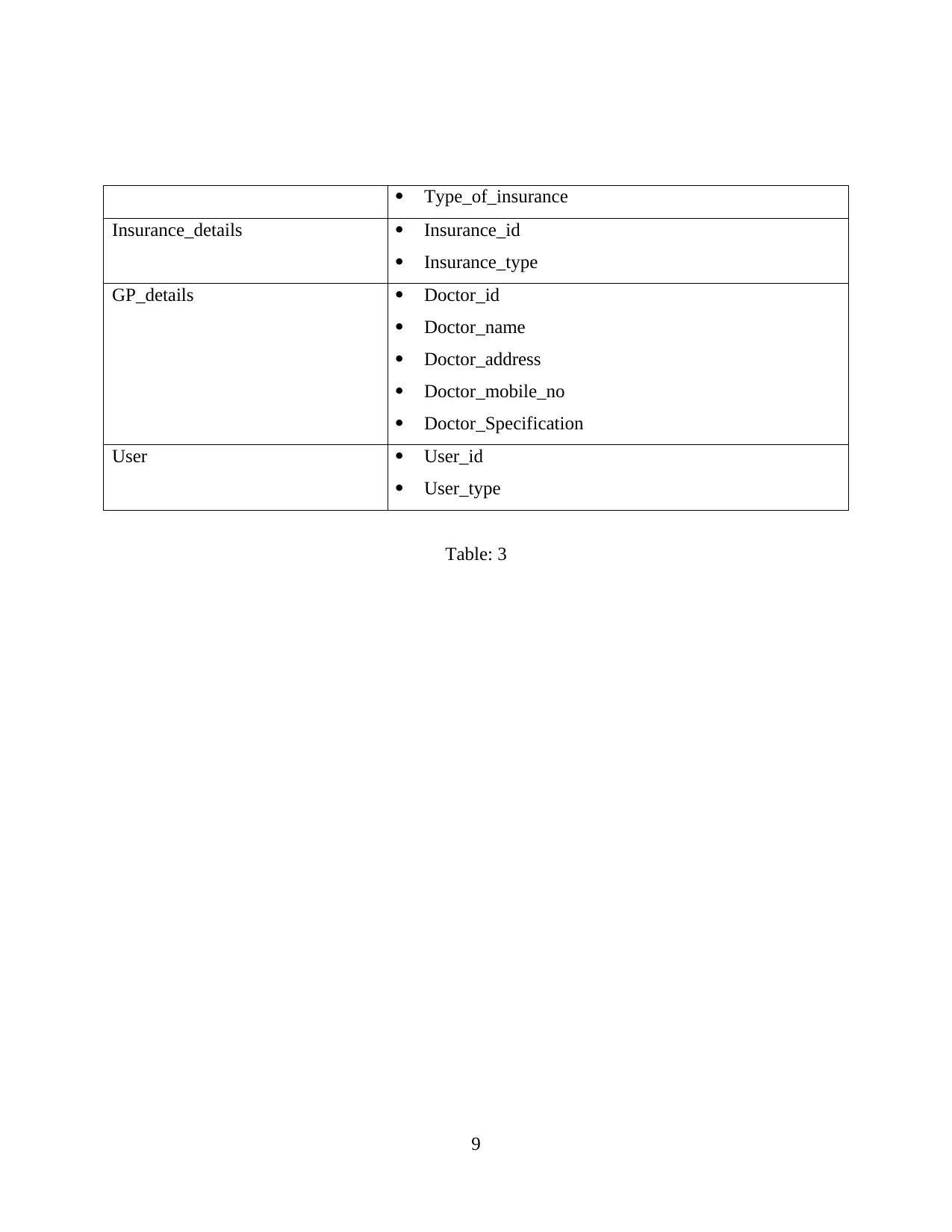
Type_of_insurance
Insurance_details Insurance_id
Insurance_type
GP_details Doctor_id
Doctor_name
Doctor_address
Doctor_mobile_no
Doctor_Specification
User User_id
User_type
Table: 3
9
Insurance_details Insurance_id
Insurance_type
GP_details Doctor_id
Doctor_name
Doctor_address
Doctor_mobile_no
Doctor_Specification
User User_id
User_type
Table: 3
9
⊘ This is a preview!⊘
Do you want full access?
Subscribe today to unlock all pages.
Trusted by 1+ million students worldwide
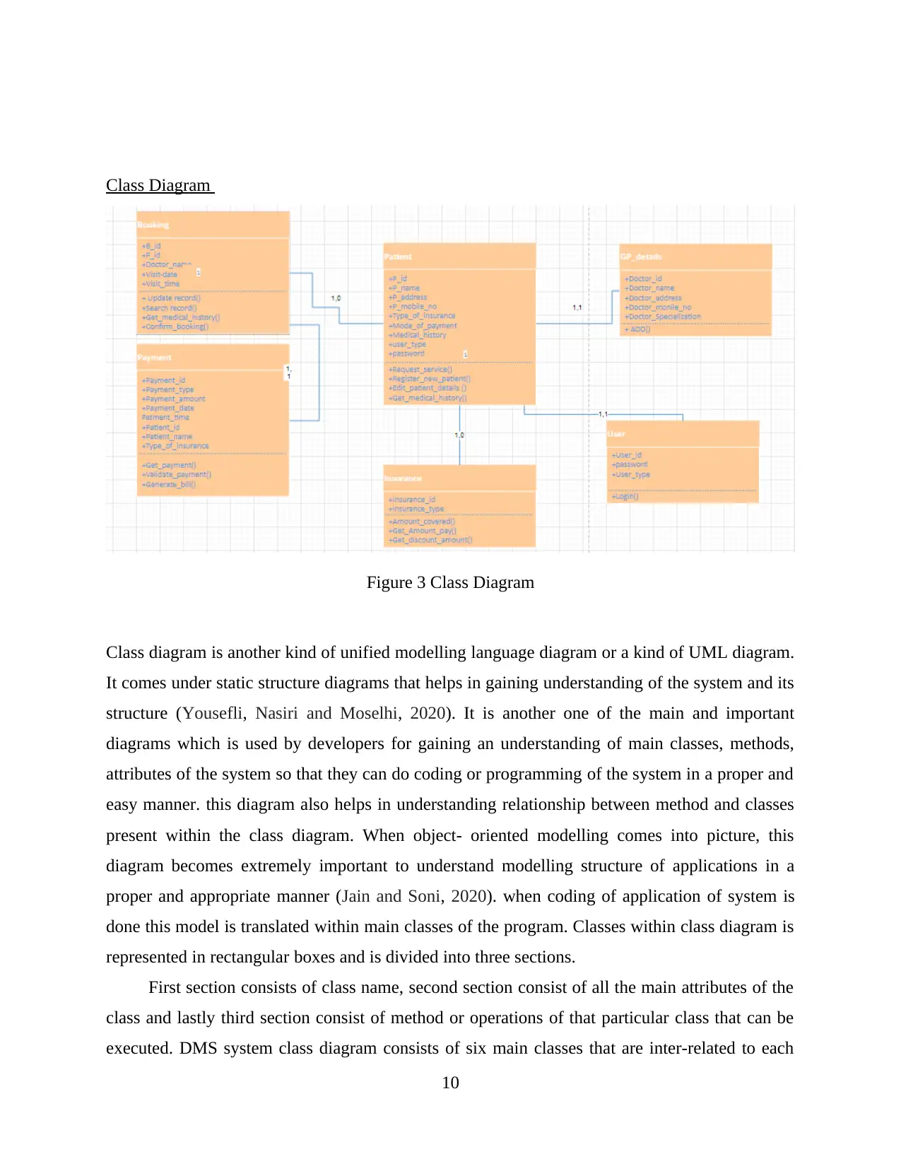
Class Diagram
Figure 3 Class Diagram
Class diagram is another kind of unified modelling language diagram or a kind of UML diagram.
It comes under static structure diagrams that helps in gaining understanding of the system and its
structure (Yousefli, Nasiri and Moselhi, 2020). It is another one of the main and important
diagrams which is used by developers for gaining an understanding of main classes, methods,
attributes of the system so that they can do coding or programming of the system in a proper and
easy manner. this diagram also helps in understanding relationship between method and classes
present within the class diagram. When object- oriented modelling comes into picture, this
diagram becomes extremely important to understand modelling structure of applications in a
proper and appropriate manner (Jain and Soni, 2020). when coding of application of system is
done this model is translated within main classes of the program. Classes within class diagram is
represented in rectangular boxes and is divided into three sections.
First section consists of class name, second section consist of all the main attributes of the
class and lastly third section consist of method or operations of that particular class that can be
executed. DMS system class diagram consists of six main classes that are inter-related to each
10
Paraphrase This Document
Need a fresh take? Get an instant paraphrase of this document with our AI Paraphraser
other. Six main classes are: Booking, Payment, Patient, User, Insurance and GP-Details. All the
classes had different relationship with each other. Some of them have one to one relationship,
some of them have one to many and some of them have many to many relationships. These
relationships have been explained in the above class diagram of DMS system.
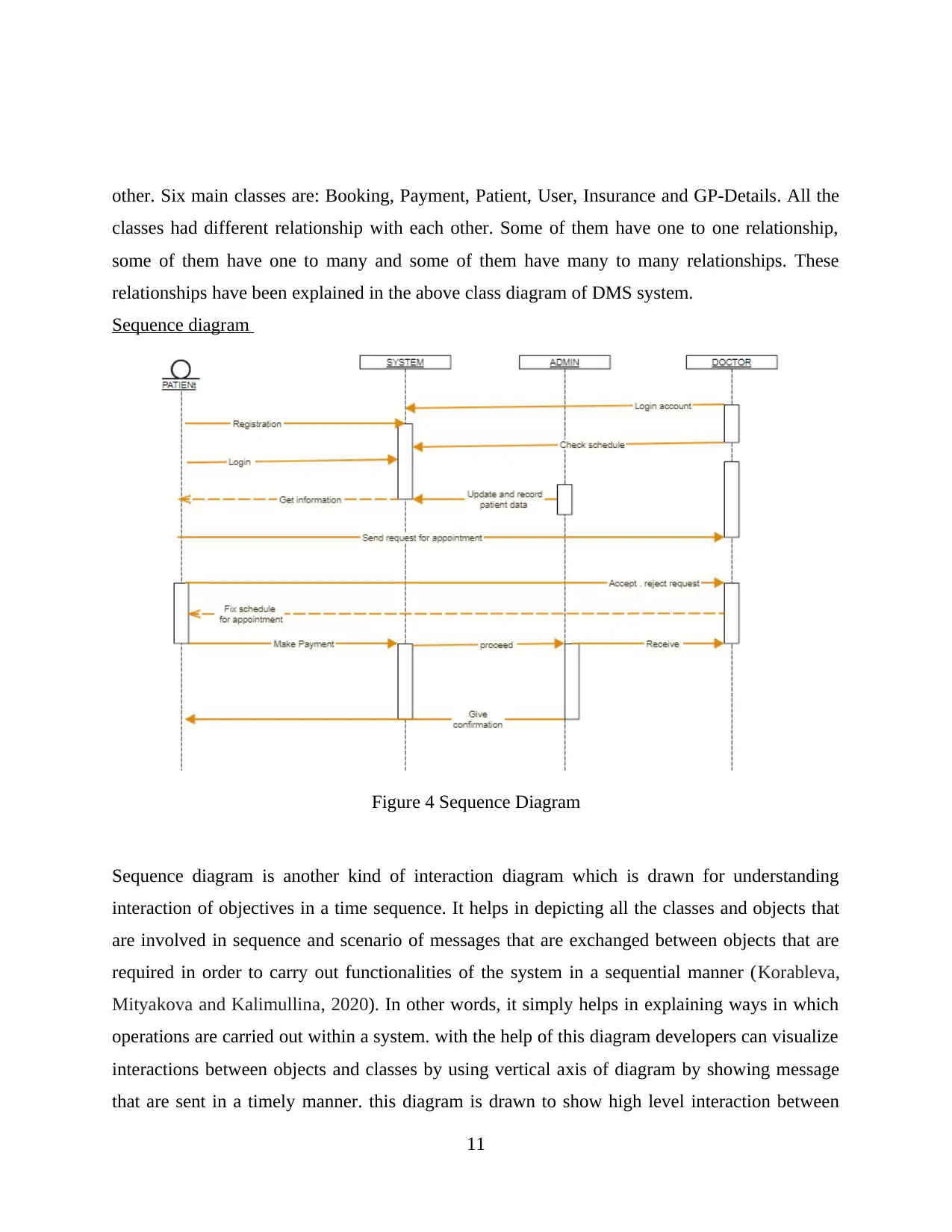
Sequence diagram
Figure 4 Sequence Diagram
Sequence diagram is another kind of interaction diagram which is drawn for understanding
interaction of objectives in a time sequence. It helps in depicting all the classes and objects that
are involved in sequence and scenario of messages that are exchanged between objects that are
required in order to carry out functionalities of the system in a sequential manner (Korableva,
Mityakova and Kalimullina, 2020). In other words, it simply helps in explaining ways in which
operations are carried out within a system. with the help of this diagram developers can visualize
interactions between objects and classes by using vertical axis of diagram by showing message
that are sent in a timely manner. this diagram is drawn to show high level interaction between
11
classes had different relationship with each other. Some of them have one to one relationship,
some of them have one to many and some of them have many to many relationships. These
relationships have been explained in the above class diagram of DMS system.
Sequence diagram
Figure 4 Sequence Diagram
Sequence diagram is another kind of interaction diagram which is drawn for understanding
interaction of objectives in a time sequence. It helps in depicting all the classes and objects that
are involved in sequence and scenario of messages that are exchanged between objects that are
required in order to carry out functionalities of the system in a sequential manner (Korableva,
Mityakova and Kalimullina, 2020). In other words, it simply helps in explaining ways in which
operations are carried out within a system. with the help of this diagram developers can visualize
interactions between objects and classes by using vertical axis of diagram by showing message
that are sent in a timely manner. this diagram is drawn to show high level interaction between
11
objects and provides a direction for handing the system. in the above sequence diagram of DMS
system interaction between system, patients, doctors and administrator has been explained
clearly. In this diagram each object and class have its own timeline on which messages are sent
and received so that use of operations at that time can be understood (Planas and Cabot, 2020).
For example: patients interact with the system for entering their personal details, access data
from the system for booking an appointment with the doctor. In this diagram step by step process
of the system is explained in a clear manner. It is another important diagram which is required to
be drawn so that time to time interaction of users with the system can be understood.
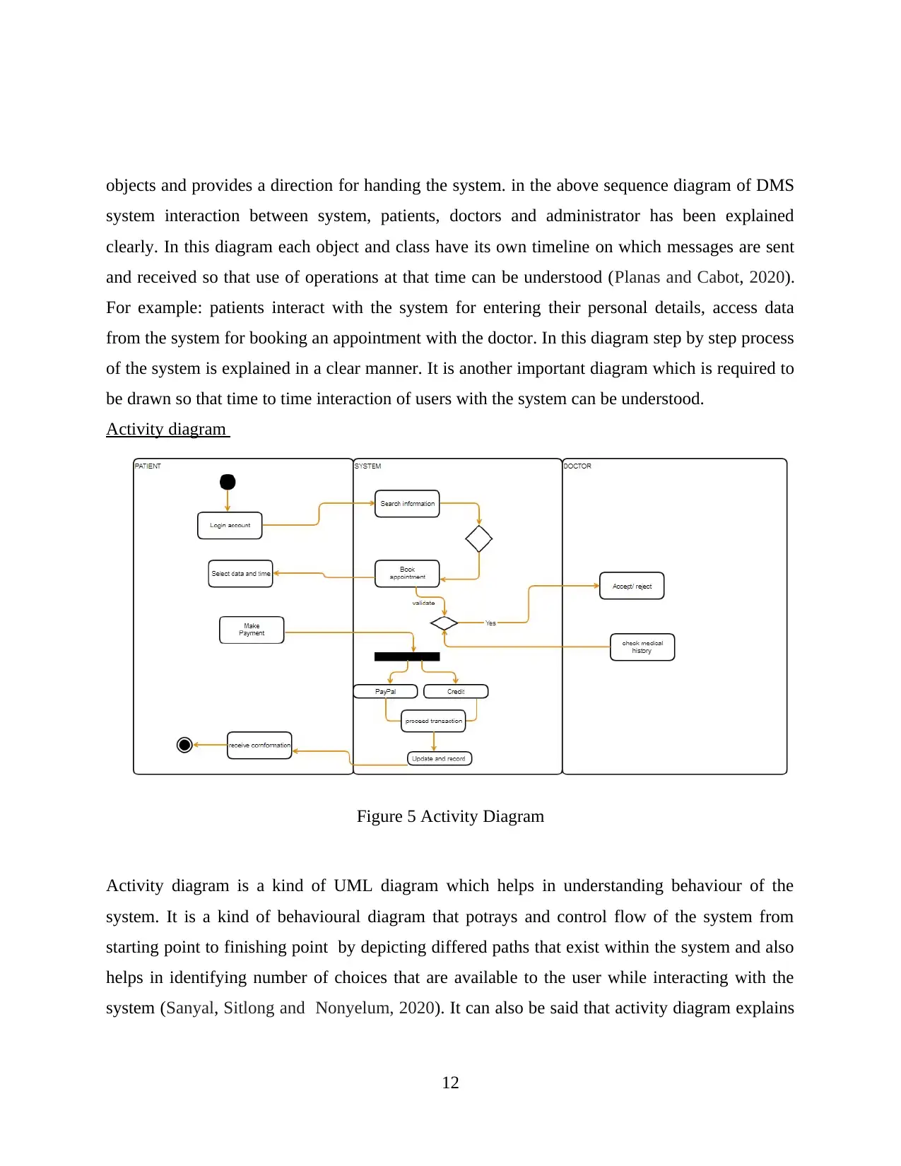
Activity diagram
Figure 5 Activity Diagram
Activity diagram is a kind of UML diagram which helps in understanding behaviour of the
system. It is a kind of behavioural diagram that potrays and control flow of the system from
starting point to finishing point by depicting differed paths that exist within the system and also
helps in identifying number of choices that are available to the user while interacting with the
system (Sanyal, Sitlong and Nonyelum, 2020). It can also be said that activity diagram explains
12
system interaction between system, patients, doctors and administrator has been explained
clearly. In this diagram each object and class have its own timeline on which messages are sent
and received so that use of operations at that time can be understood (Planas and Cabot, 2020).
For example: patients interact with the system for entering their personal details, access data
from the system for booking an appointment with the doctor. In this diagram step by step process
of the system is explained in a clear manner. It is another important diagram which is required to
be drawn so that time to time interaction of users with the system can be understood.
Activity diagram
Figure 5 Activity Diagram
Activity diagram is a kind of UML diagram which helps in understanding behaviour of the
system. It is a kind of behavioural diagram that potrays and control flow of the system from
starting point to finishing point by depicting differed paths that exist within the system and also
helps in identifying number of choices that are available to the user while interacting with the
system (Sanyal, Sitlong and Nonyelum, 2020). It can also be said that activity diagram explains
12
⊘ This is a preview!⊘
Do you want full access?
Subscribe today to unlock all pages.
Trusted by 1+ million students worldwide
1 out of 19
Related Documents


Your All-in-One AI-Powered Toolkit for Academic Success.
+13062052269
info@desklib.com
Available 24*7 on WhatsApp / Email
![[object Object]](/_next/static/media/star-bottom.7253800d.svg)
Unlock your academic potential
Copyright © 2020–2026 A2Z Services. All Rights Reserved. Developed and managed by ZUCOL.