ME401: Detailed Report on Double Reduction Spur Gearbox Design

Verified

Added on  2022/10/19

|20
|1276
|309
Report
AI Summary
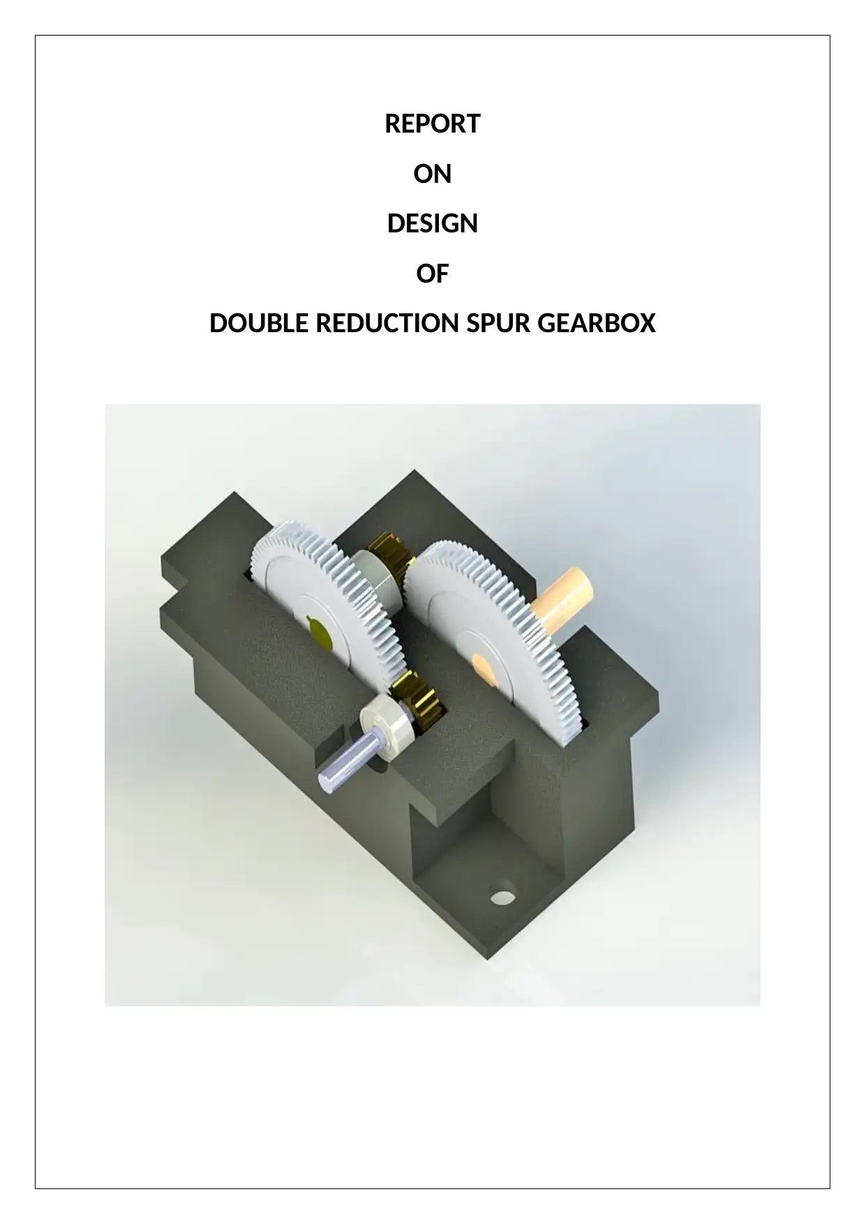
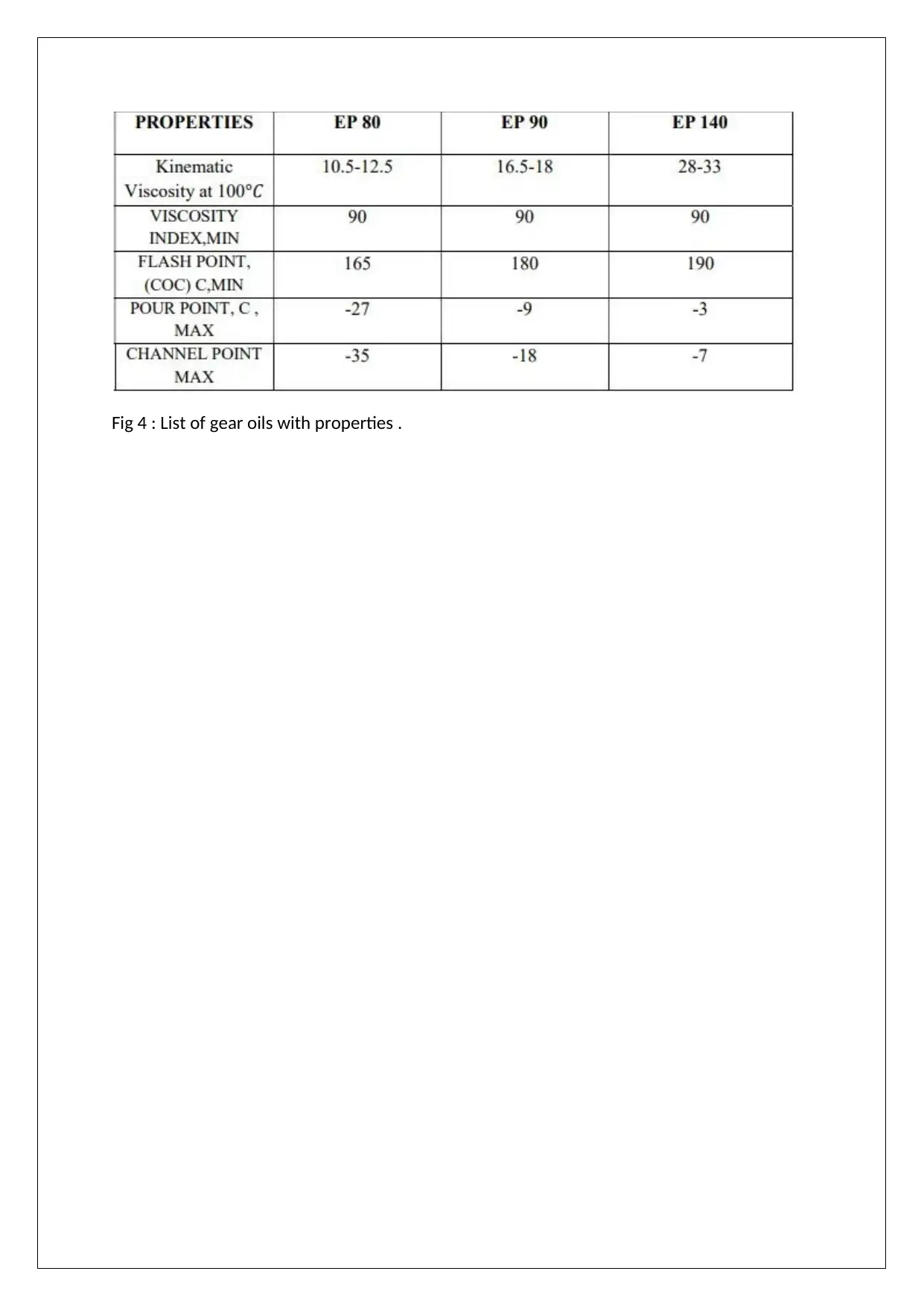
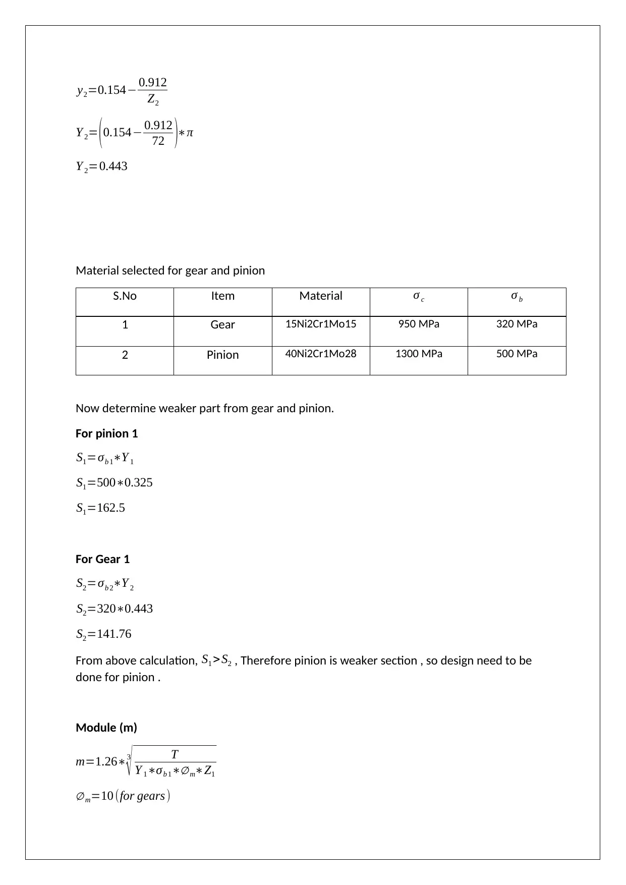
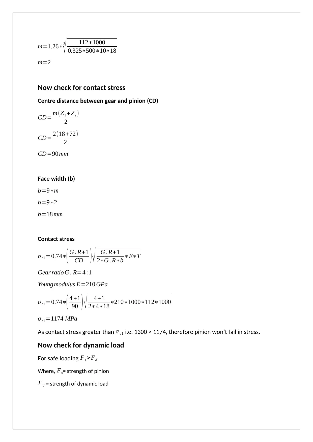
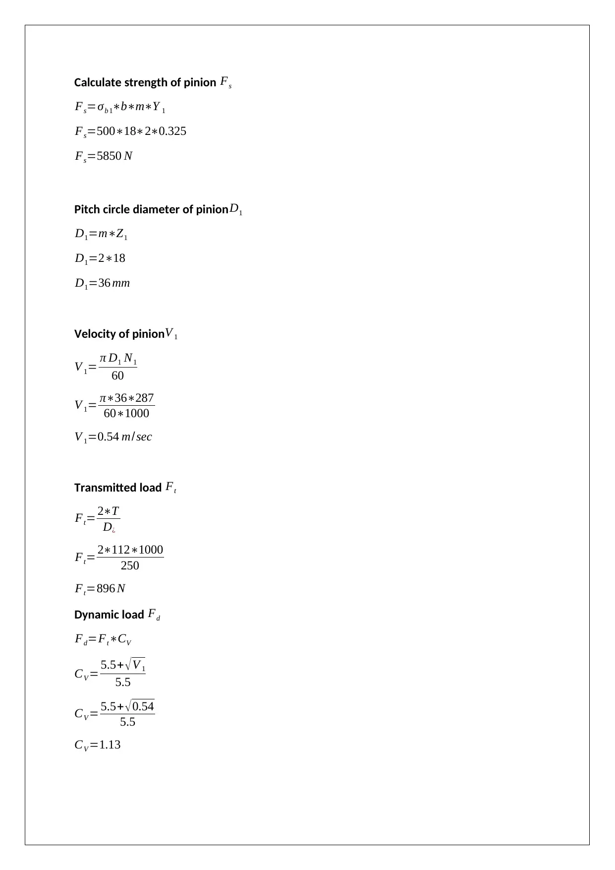
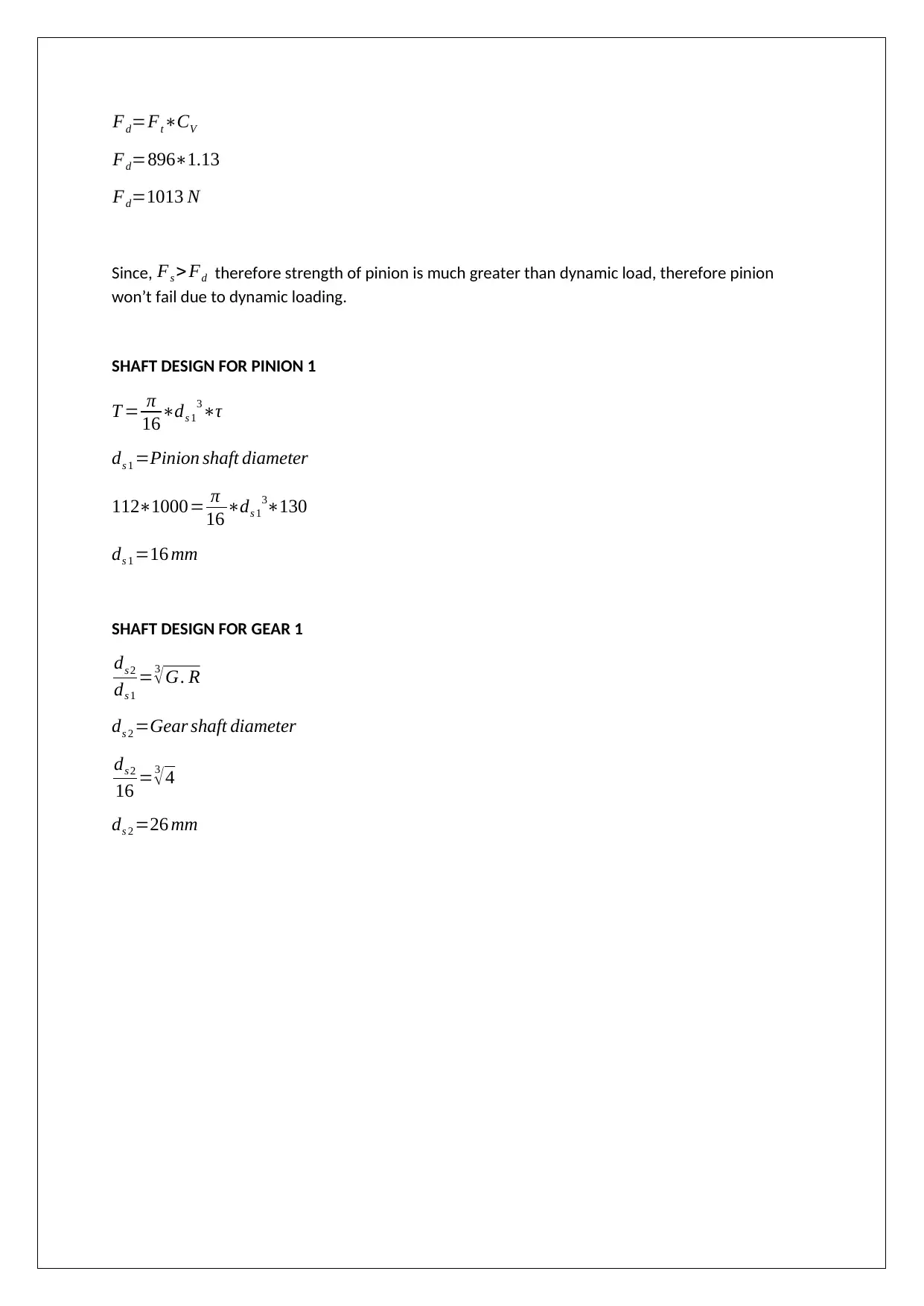
This report presents the design of a double reduction spur gearbox, a crucial component for power transmission in industrial applications like crane winches. The report begins with material selection based on desired properties and application requirements. Key calculations include determining gear ratios, module, and face width to achieve the specified input and output speeds and torque. The design process involves analyzing gear and pinion strength, considering both static and dynamic loads to prevent failure. Shaft design calculations are performed for both input, intermediate and output shafts, ensuring adequate strength and rigidity. Bearing selection is also included, with specific bearing models recommended based on load and dimensional requirements. The report adheres to design requirements, ensuring efficient performance, proper space utilization, and economical material choices. The calculations are based on the textbook "Fundamentals of Machine Component Design" by Robert C. Juvinall & Kurt M.Marshek.
Document Page
REPORT
ON
DESIGN
OF
DOUBLE REDUCTION SPUR GEARBOX
tabler-icon-diamond-filled.svg

Paraphrase This Document

Need a fresh take? Get an instant paraphrase of this document with our AI Paraphraser
Document Page
Nomenclature
N1= Speed of pinion 1 in RPM
N2= Speed of Gear 1 in RPM
N3= Speed of pinion 2 in RPM
N4= Speed of Gear 2 in RPM
Z1= Number of teeth on pinion 1
Z2= Number of teeth on Gear 1
D1= Pitch circle diameter of pinion 1
D2= Pitch circle diameter of gear 1
D3= Pitch circle diameter of pinion 2
D4= Pitch circle diameter of gear 2
Y = Lewis factor
m = Module
b = Face width
CD =Centre distance between gears
σ c1= Contact stress
Fs =Pinion/gear strength
Fd =Dynamic load
FT =Transmission load
ds 1 =Input shaft diameter
ds 2 =Intermediate shaft diameter
ds 3 =Output shaft diameter
V =Velocity of gear/pinion
Document Page
REDUCTION TYPE GEARBOX
Gearbox is a mechanical device generally used to transmit power from source to output
shaft. Power can be transmit by set of gears aligned in such a manner to get desired output
in required direction. Reduction type gearbox is used where input speed can be reduced to
get low speed at high torque ,The number of gears used in this system is completely depend
on reduction ratio and input speed .
Material Selection
For selecting material of gears, the following data need be calculated:
Speed of driving and driven gear
Gear ratio
Power transmitted
Centre distance between meshed gears.
Gear drive design requirements
The main requirements to design a gear drive shown below:
Gear teeth should have fatigue and wear characteristics to work satisfactory in its
designed life.
It is required that gear teeth have sufficient strength that it can withstand static and
dynamic loading so that it may not fail under during working conditions.
Proper utilization of space.
Deflection of shaft and gear alignment need to be considered as it highly effect the
performance.
Material used to be economical and easily available.
For efficient performance, the lubrication in gears is necessary.
Based on requirements, materials available for gear shown below.
Fig 1 : Material list for gears
Document Page
Material for Shafts
Essential property of shaft material :-
High strength
High wear resistant
Low notch sensitivity factor
Good machinability
Fig 2 : Material list for shaft
Material for Casing
Essential property of casing material:–
High strength
Less weight
High ductility
Fig 3 : Material list for casing
IMPORTANCE OF GEAR OIL (LUBRICATION)
Gear oil is one of the most important part of gearbox due to its following benefits:-
Gear oil provides lubrication to the different parts of gearbox.
Reduce friction between mating parts cause less wear and tear.
Increase life of gears.
Act as a cooling agent and maintain temperature in casing chamber.
Remove dirt and wear off parts from gearbox parts.
tabler-icon-diamond-filled.svg

Paraphrase This Document

Need a fresh take? Get an instant paraphrase of this document with our AI Paraphraser
Document Page
Fig 4 : List of gear oils with properties .
Document Page
Design requirements
Mass of castings: 450Kg
Lift height: 8m
As an assumption the radius of drum: 250mm (can be changed in the design)
Torque to be delivered on the assumed drum radius of 250mm: 112N.m
Power to be delivered: 15kW (this is maximum and can be changed)
Input speed: 30rev/s
Output speed: 2rev/s
Loads have a moderate shock effect on the winch
Output shaft and input shafts in-line or at right angles
Base mounted with 4 bolts
Continuous operation
6-year life, 8 hours a day, 5 days a week
Low maintenance
Competitive cost
Nominal operating conditions of industrial locations
Input and output shafts are standard size for typical couplings.
Include safety factor of 2
Low noise <85dB
GIVEN DATA
Input power =15 kW
Torque T =112 Nm
Input speed = 30 rev / sec
Output required speed = 2 rev /sec
SOLUTION (ROBERT,2013)
Document Page
Input speed in rpm
ω1= 2 π N 1
60
30=2 π N1
60
N1 300rpm
Output speed in rpm
ω4= 2 π N 4
60
2= 2 π N 4
60
N4 =20 rpm
Total reduction in gearbox required
Speed ratio = ω1
ω4
Speed ratio = 30
2 =15
Now from above calculation, it is clear that 15 times reduced speed is required at the output
gear i.e. gear 4. As double reduction spur gearbox is needed to be design to deliver 15 times
less speed .The reduction should be done in two stages.
First stage reduction = 4:1
Second stage reduction = 3.75:1
DESIGN FOR FIRST STAGE REDUCTION
Gear ratio required = 4:1
Speed at input shaft /Input pinion N1=300 rpm
Pressure angle α =20 °
Minimum number of teeth to avoid interference Z1 = 2
sin2 α
Z1 = 2
sin2 20
tabler-icon-diamond-filled.svg

Paraphrase This Document

Need a fresh take? Get an instant paraphrase of this document with our AI Paraphraser
Document Page
Z1 =18
Therefore number of teeth on pinion 1 is 18
Speed of Gear 1
N1
N 2
=4 :1
300
N2
=4 :1
N2=75 rpm
Number of teeth on Gear 1
Z2
Z1
=4 :1
Z2
18 =4 :1
Z2 =72
Calculate lewis factor (Y)
Y =πy
y=0.154 0.912
Z
For pinion 1
Y 1=πy1
y1=0.154 0.912
Z1
Y 1= (0.154 0.912
18 )π
Y 1=0.325
For gear
Y 2=πy2
Document Page
y2=0.154 0.912
Z2
Y 2= (0.154 0.912
72 )π
Y 2=0.443
Material selected for gear and pinion
S.No Item Material σ c σ b
1 Gear 15Ni2Cr1Mo15 950 MPa 320 MPa
2 Pinion 40Ni2Cr1Mo28 1300 MPa 500 MPa
Now determine weaker part from gear and pinion.
For pinion 1
S1=σb 1Y 1
S1=5000.325
S1=162.5
For Gear 1
S2=σb 2Y 2
S2=3200.443
S2=141.76
From above calculation, S1 > S2 , Therefore pinion is weaker section , so design need to be
done for pinion .
Module (m)
m=1.263
T
Y 1σb 1 mZ1
m=10 (for gears)
Document Page
m=1.263
1121000
0.3255001018
m=2
Now check for contact stress
Centre distance between gear and pinion (CD)
CD= m(Z1 + Z2 )
2
CD= 2(18+72)
2
CD=90 mm
Face width (b)
b=9m
b=92
b=18 mm
Contact stress
σ c1=0.74( G . R+1
CD ) G. R+1
2G . Rb ET
Gear ratio G . R=4 :1
Young modulus E=210 GPa
σ c1=0.74( 4 +1
90 ) 4+1
241821010001121000
σ c1=1174 MPa
As contact stress greater than σ c1 i.e. 1300 > 1174, therefore pinion won’t fail in stress.
Now check for dynamic load
For safe loading Fs > Fd
Where, Fs= strength of pinion
Fd = strength of dynamic load
tabler-icon-diamond-filled.svg

Paraphrase This Document

Need a fresh take? Get an instant paraphrase of this document with our AI Paraphraser
Document Page
Calculate strength of pinion Fs
Fs=σb 1bmY 1
Fs=5001820.325
Fs=5850 N
Pitch circle diameter of pinion D1
D1=mZ1
D1=218
D1=36 mm
Velocity of pinion V 1
V 1= π D1 N1
60
V 1= π36287
601000
V 1=0.54 m/sec
Transmitted load Ft
Ft= 2T
D¿
Ft= 21121000
250
Ft=896 N
Dynamic load Fd
Fd=FtCV
CV = 5.5+ V 1
5.5
CV = 5.5+ 0.54
5.5
CV =1.13
Document Page
Fd=FtCV
Fd=8961.13
Fd=1013 N
Since, Fs > Fd therefore strength of pinion is much greater than dynamic load, therefore pinion
won’t fail due to dynamic loading.
SHAFT DESIGN FOR PINION 1
T = π
16ds 1
3τ
ds 1 =Pinion shaft diameter
1121000= π
16 ds 1
3130
ds 1 =16 mm
SHAFT DESIGN FOR GEAR 1
ds 2
ds 1
=3
G. R
ds 2 =Gear shaft diameter
ds 2
16 =3
4
ds 2 =26 mm
chevron_up_icon
1 out of 20
circle_padding
hide_on_mobile
zoom_out_icon
[object Object]