Project: Parametric Modeling of a 4x4 Drive Shaft using Siemens NX
VerifiedAdded on  2022/09/15
|4
|1451
|17
Project
AI Summary
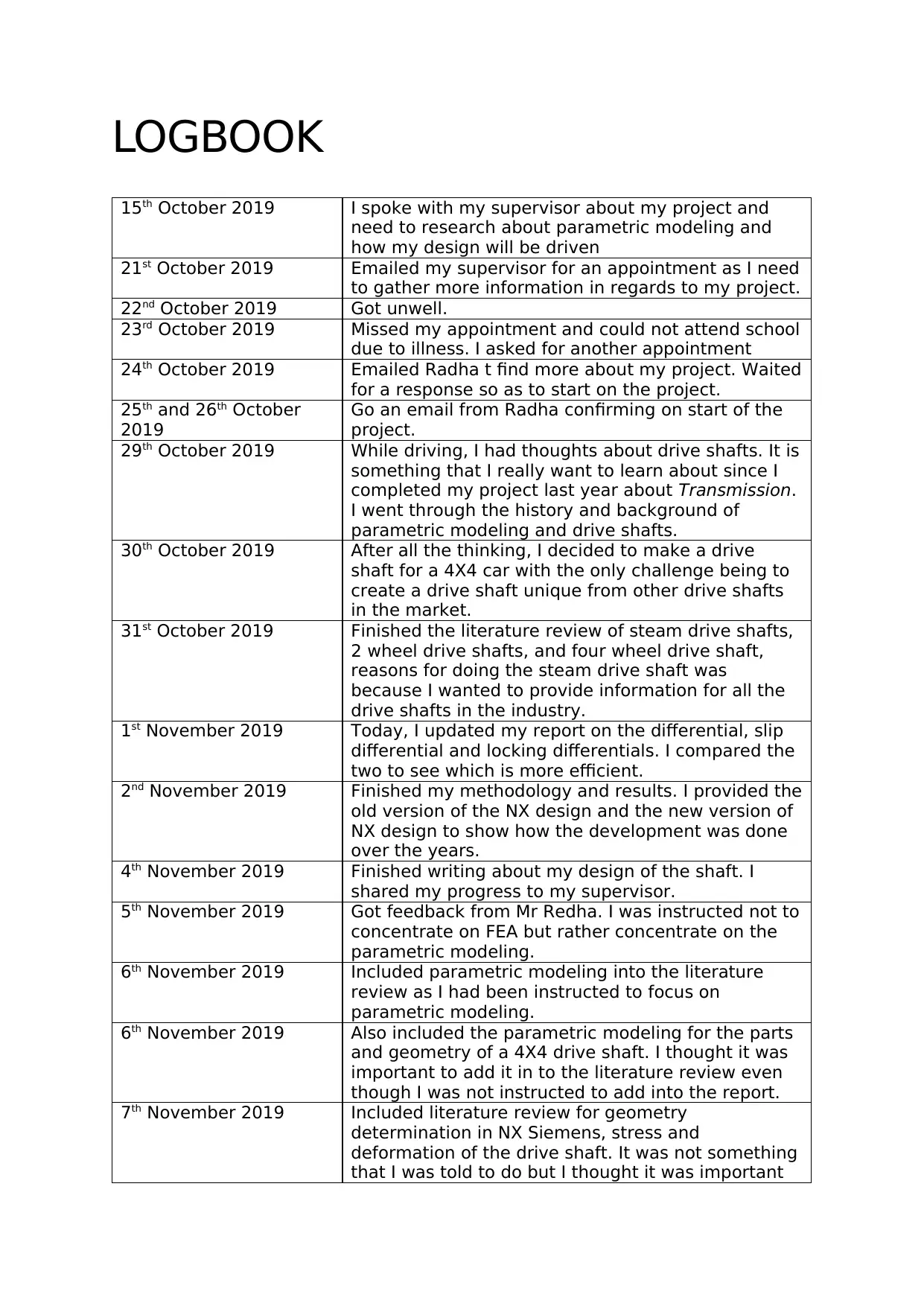
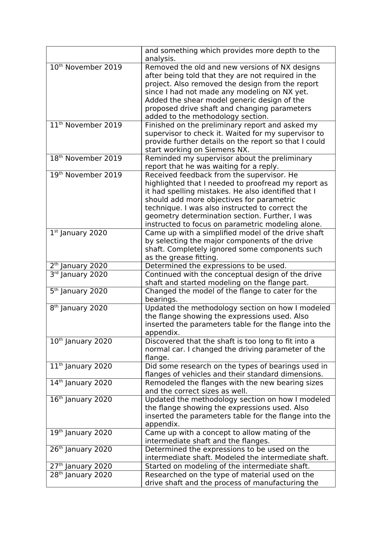
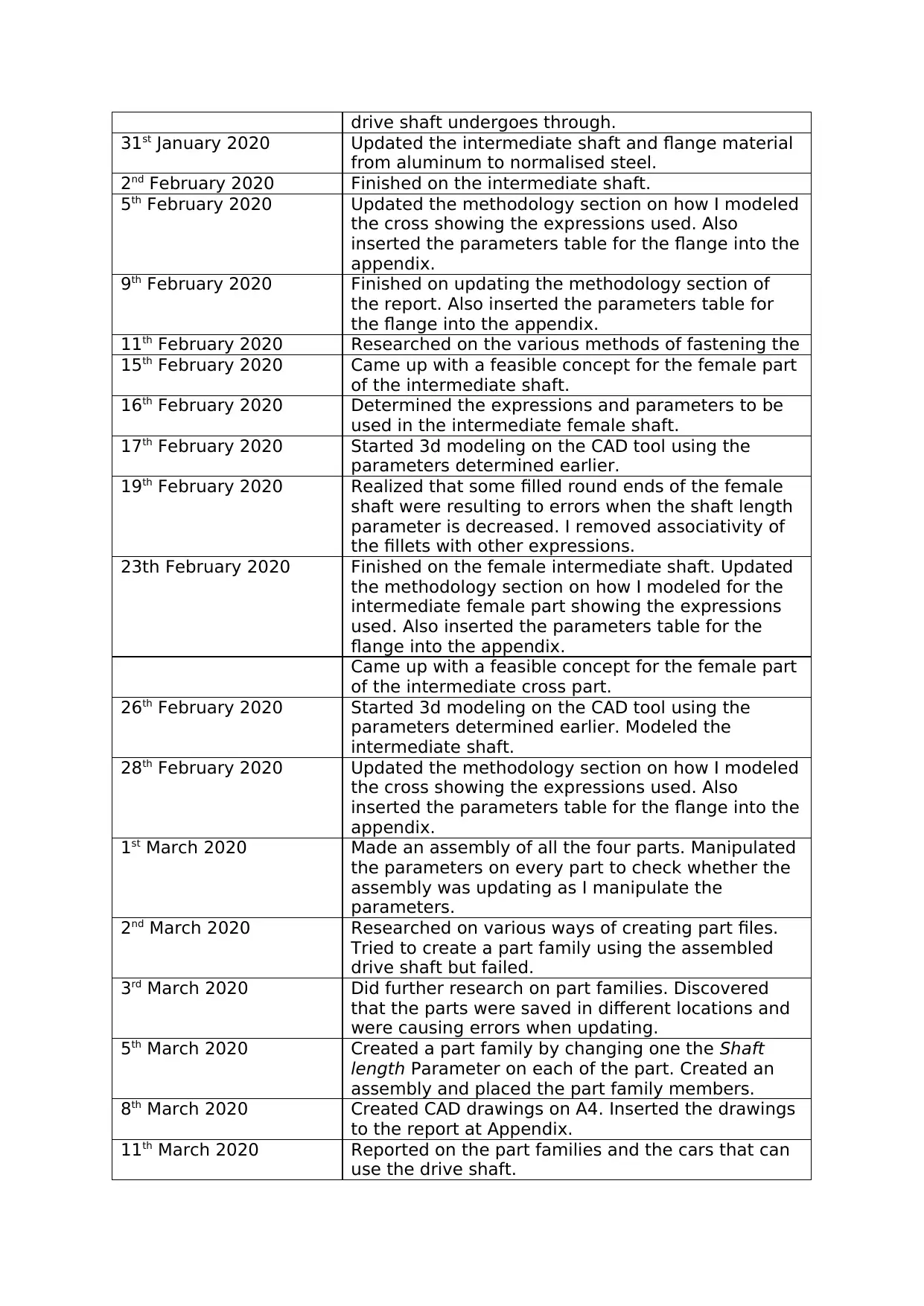
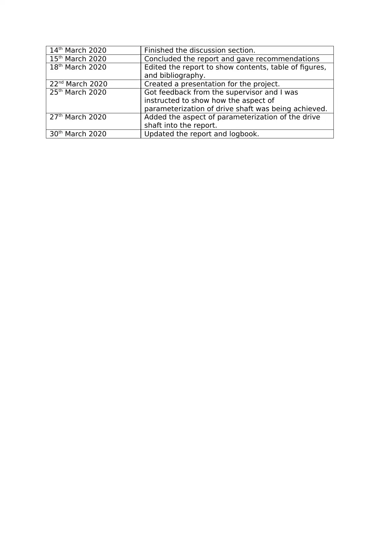
This project documents the process of parametric modeling a 4x4 drive shaft using Siemens NX. The project begins with initial research and literature review on drive shafts, parametric modeling, and relevant components. The student outlines the design process, including determining expressions, modeling individual parts (flange, intermediate shaft, cross), and assembling the drive shaft. The methodology section details the expressions used and parameters for each component. The student then creates a part family and CAD drawings, concluding with a discussion of the results, recommendations, and a presentation. The project highlights the application of parametric modeling techniques in mechanical engineering design, focusing on the iterative process of design, analysis, and refinement using Siemens NX.

LOGBOOK
15th October 2019 I spoke with my supervisor about my project and
need to research about parametric modeling and
how my design will be driven
21st October 2019 Emailed my supervisor for an appointment as I need
to gather more information in regards to my project.
22nd October 2019 Got unwell.
23rd October 2019 Missed my appointment and could not attend school
due to illness. I asked for another appointment
24th October 2019 Emailed Radha t find more about my project. Waited
for a response so as to start on the project.
25th and 26th October
2019
Go an email from Radha confirming on start of the
project.
29th October 2019 While driving, I had thoughts about drive shafts. It is
something that I really want to learn about since I
completed my project last year about Transmission.
I went through the history and background of
parametric modeling and drive shafts.
30th October 2019 After all the thinking, I decided to make a drive
shaft for a 4X4 car with the only challenge being to
create a drive shaft unique from other drive shafts
in the market.
31st October 2019 Finished the literature review of steam drive shafts,
2 wheel drive shafts, and four wheel drive shaft,
reasons for doing the steam drive shaft was
because I wanted to provide information for all the
drive shafts in the industry.
1st November 2019 Today, I updated my report on the differential, slip
differential and locking differentials. I compared the
two to see which is more efficient.
2nd November 2019 Finished my methodology and results. I provided the
old version of the NX design and the new version of
NX design to show how the development was done
over the years.
4th November 2019 Finished writing about my design of the shaft. I
shared my progress to my supervisor.
5th November 2019 Got feedback from Mr Redha. I was instructed not to
concentrate on FEA but rather concentrate on the
parametric modeling.
6th November 2019 Included parametric modeling into the literature
review as I had been instructed to focus on
parametric modeling.
6th November 2019 Also included the parametric modeling for the parts
and geometry of a 4X4 drive shaft. I thought it was
important to add it in to the literature review even
though I was not instructed to add into the report.
7th November 2019 Included literature review for geometry
determination in NX Siemens, stress and
deformation of the drive shaft. It was not something
that I was told to do but I thought it was important
Secure Best Marks with AI Grader
Need help grading? Try our AI Grader for instant feedback on your assignments.

and something which provides more depth to the
analysis.
10th November 2019 Removed the old and new versions of NX designs
after being told that they are not required in the
project. Also removed the design from the report
since I had not made any modeling on NX yet.
Added the shear model generic design of the
proposed drive shaft and changing parameters
added to the methodology section.
11th November 2019 Finished on the preliminary report and asked my
supervisor to check it. Waited for my supervisor to
provide further details on the report so that I could
start working on Siemens NX.
18th November 2019 Reminded my supervisor about the preliminary
report that he was waiting for a reply.
19th November 2019 Received feedback from the supervisor. He
highlighted that I needed to proofread my report as
it had spelling mistakes. He also identified that I
should add more objectives for parametric
technique. I was also instructed to correct the
geometry determination section. Further, I was
instructed to focus on parametric modeling alone.
1st January 2020 Came up with a simplified model of the drive shaft
by selecting the major components of the drive
shaft. Completely ignored some components such
as the grease fitting.
2th January 2020 Determined the expressions to be used.
3rd January 2020 Continued with the conceptual design of the drive
shaft and started modeling on the flange part.
5th January 2020 Changed the model of the flange to cater for the
bearings.
8th January 2020 Updated the methodology section on how I modeled
the flange showing the expressions used. Also
inserted the parameters table for the flange into the
appendix.
10th January 2020 Discovered that the shaft is too long to fit into a
normal car. I changed the driving parameter of the
flange.
11th January 2020 Did some research on the types of bearings used in
flanges of vehicles and their standard dimensions.
14th January 2020 Remodeled the flanges with the new bearing sizes
and the correct sizes as well.
16th January 2020 Updated the methodology section on how I modeled
the flange showing the expressions used. Also
inserted the parameters table for the flange into the
appendix.
19th January 2020 Came up with a concept to allow mating of the
intermediate shaft and the flanges.
26th January 2020 Determined the expressions to be used on the
intermediate shaft. Modeled the intermediate shaft.
27th January 2020 Started on modeling of the intermediate shaft.
28th January 2020 Researched on the type of material used on the
drive shaft and the process of manufacturing the

drive shaft undergoes through.
31st January 2020 Updated the intermediate shaft and flange material
from aluminum to normalised steel.
2nd February 2020 Finished on the intermediate shaft.
5th February 2020 Updated the methodology section on how I modeled
the cross showing the expressions used. Also
inserted the parameters table for the flange into the
appendix.
9th February 2020 Finished on updating the methodology section of
the report. Also inserted the parameters table for
the flange into the appendix.
11th February 2020 Researched on the various methods of fastening the
15th February 2020 Came up with a feasible concept for the female part
of the intermediate shaft.
16th February 2020 Determined the expressions and parameters to be
used in the intermediate female shaft.
17th February 2020 Started 3d modeling on the CAD tool using the
parameters determined earlier.
19th February 2020 Realized that some filled round ends of the female
shaft were resulting to errors when the shaft length
parameter is decreased. I removed associativity of
the fillets with other expressions.
23th February 2020 Finished on the female intermediate shaft. Updated
the methodology section on how I modeled for the
intermediate female part showing the expressions
used. Also inserted the parameters table for the
flange into the appendix.
Came up with a feasible concept for the female part
of the intermediate cross part.
26th February 2020 Started 3d modeling on the CAD tool using the
parameters determined earlier. Modeled the
intermediate shaft.
28th February 2020 Updated the methodology section on how I modeled
the cross showing the expressions used. Also
inserted the parameters table for the flange into the
appendix.
1st March 2020 Made an assembly of all the four parts. Manipulated
the parameters on every part to check whether the
assembly was updating as I manipulate the
parameters.
2nd March 2020 Researched on various ways of creating part files.
Tried to create a part family using the assembled
drive shaft but failed.
3rd March 2020 Did further research on part families. Discovered
that the parts were saved in different locations and
were causing errors when updating.
5th March 2020 Created a part family by changing one the Shaft
length Parameter on each of the part. Created an
assembly and placed the part family members.
8th March 2020 Created CAD drawings on A4. Inserted the drawings
to the report at Appendix.
11th March 2020 Reported on the part families and the cars that can
use the drive shaft.

14th March 2020 Finished the discussion section.
15th March 2020 Concluded the report and gave recommendations
18th March 2020 Edited the report to show contents, table of figures,
and bibliography.
22nd March 2020 Created a presentation for the project.
25th March 2020 Got feedback from the supervisor and I was
instructed to show how the aspect of
parameterization of drive shaft was being achieved.
27th March 2020 Added the aspect of parameterization of the drive
shaft into the report.
30th March 2020 Updated the report and logbook.
1 out of 4

Your All-in-One AI-Powered Toolkit for Academic Success.
 +13062052269
info@desklib.com
Available 24*7 on WhatsApp / Email
Unlock your academic potential
© 2024  |  Zucol Services PVT LTD  |  All rights reserved.