Training Booklet: Drive Shaft Material Testing and Cosmetic Fittings
VerifiedAdded on 2023/03/21
|21
|3871
|48
Report
AI Summary
This report serves as a training booklet covering the materials and testing of drive shafts, along with an introduction to cosmetic fittings. It details the principles and features of common material testing methods like tensile strength, impact strength, hardness, creep strength, fatigue resistance, and torsional strength. Non-destructive methods for assessing drive shaft materials, such as dye penetrant, magnetic particle, ultrasonic, and radiography, are explained with example applications. The report includes data and analysis from mechanical tests on composites, polymers, ceramics, and metals, justifying their applications in drive shaft production. Formulas for calculating mechanical test values are provided, followed by a discussion and conclusion on the importance of material testing in drive shaft manufacturing. Additionally, the report briefly introduces cosmetic fittings, defining them as automotive parts that enhance customization, comfort, and visual appeal.

TRAINING BOOKLET ON DRIVE SHAFTS AND COSMETIC FITTINGS
By
Course
Instructor
Institution
Location
Date
By
Course
Instructor
Institution
Location
Date
Paraphrase This Document
Need a fresh take? Get an instant paraphrase of this document with our AI Paraphraser
Materials used in the manufacture of drive shafts
Abstract
A drive shaft is a mechanical structure that is applied for the purposes of transmitting rotation
and torque. Drive shafts are torque carriers hence are subjected to shear and torsion stresses.
These stresses should match the differences that exist between the load and the input torque. This
means that the strength of the shafts should match the strength of the stress that is applied to
them.
Introduction
In selecting materials used in making drive shafts some factors come into play. In most cases,
aluminium, stainless steel and carbon steel are the most common materials that are used in
making drive shafts due to their good mechanical properties.
The principles, mechanical tests, as well as non-destructive methods applied in assessing the
materials selected in making drive shafts are discussed in detail in this report.
Background
Principles and features applied in material selection
These principles and features that are applied when selecting the materials used in making drive
shafts are discussed are as follows;
Tensile strength
This is the ability of materials to bear the load that is applied to them before breaking or
deforming. It is measured using tensile testing (Davis, 2011). Tensile testing is a basic type of
mechanical testing that is widely applied in choosing the material used in making of drive shafts
more so based on the quality and how the material reacts when subjected to the different kinds of
force. To test for tensile strength, a drive shaft is placed in a square area depending on the
standard machine gauge length (Aldous, 2015). Then, the shaft is held using the crossheads and
subjected to force up to a point where it fractures. The measurement of the elongated section is
taken to determine the tensile strength.
Impact strength
This is the ability of materials to absorb energy before they fracture as a result of deformation.
Impact testing is applied in determining how tough the material used in making drive shafts is.
This test outlines the quantity of energy that is taken in by a material as it fractures.
Hardness
This is the ability of materials to bear mechanical abrasion and indentation before they reach the
point of deformation (Royster, 2011). In measuring for this feature, a hardness testing machine is
applied. A disc cutter is used to cut the drive shaft into a number of pieces and then placed on the
hardness testing machine. The results obtained will form a U-shaped curve when the data is put
in the graph as the hardness levels decline when close to the middle section of the shaft. The
hardness number can range between 79- 100.2.
⊘ This is a preview!⊘
Do you want full access?
Subscribe today to unlock all pages.
Trusted by 1+ million students worldwide
Fatigue resistance
This is the ability of materials to maintain their structure regardless of the cyclic loading that is
applied to them. The fatigue resistance test examines how the materials react in cases where
there is fluctuation of loads. A standard mean load as well as a constantly changing load is
placed on the drive shaft and checked for premature failure or conflicting results (Moore, 2010).
The results should be based on how the material can be able to endure as many stress cycles as
possible without fracturing whereby there is a standard limit failure value and beyond it cracks
will develop hence causing fractures.
Creep strength
This is the stress that tends to produce raptures due to alterations in environmental conditions.
Creep failure manifests as a result of the accumulation of the creep strain causing deformation of
the drive shafts (Keyes, 2012).
Torsion strength
This gauges how the materials used in making drive shafts are able to tolerate a load that is
twisting. Here the ultimate material strength is tested by placing a torsion load and checking the
amount of torsion strength material can withstand before rupturing (T. Kevin O'Brien, 2011).
Methods applied
Non-destructive methods applied in checking materials
These methods are discussed one after another below;
Paraphrase This Document
Need a fresh take? Get an instant paraphrase of this document with our AI Paraphraser
Dye penetrant method
This technique is vital in pinpointing surface breaking weaknesses like seams, cracks, laps and
porosity. It can be used for checking non-ferrous and ferrous substances as well as materials that
are non-porous (Knight, 2018). The drive shaft is first cleaned and then sprayed, brushed or
dipped into the penetrant. Next, the excess penetrant is dried off using an instrument called a
developer thereby creating a visible indication of any flaw available on the surface of the drive
shaft. The shaft is visually inspected using ultraviolet light to show any flaws in the materials
used.
The dry penetrant technique is the best when applied in detecting flaws in weldments, forgings,
and castings especially for the shafts used in aerospace, oil, gas, and power generation industries.
Magnetic particle
This is a non-destructive method used in detecting any flaws like material cracks in precision
parts. This technique uses magnetic fields and magnetic particle components in pinpointing
cracks and defects of materials used in making a drive shaft. In most cases, these methods work
on steel, iron and also other magnetic alloys because the various materials must be magnetized
before conducting this test (Christoph, 2014). When applied in inspecting a drive shaft, this
method shows how maximum operational torque affects the shaft surface indicating it is the
weakest point of the shaft.
Magnetic particle inspection is best applied in cases where actual imperfection as it defines the
lines that show the whole crack in materials which is an added advantage when compared to the
other methods.
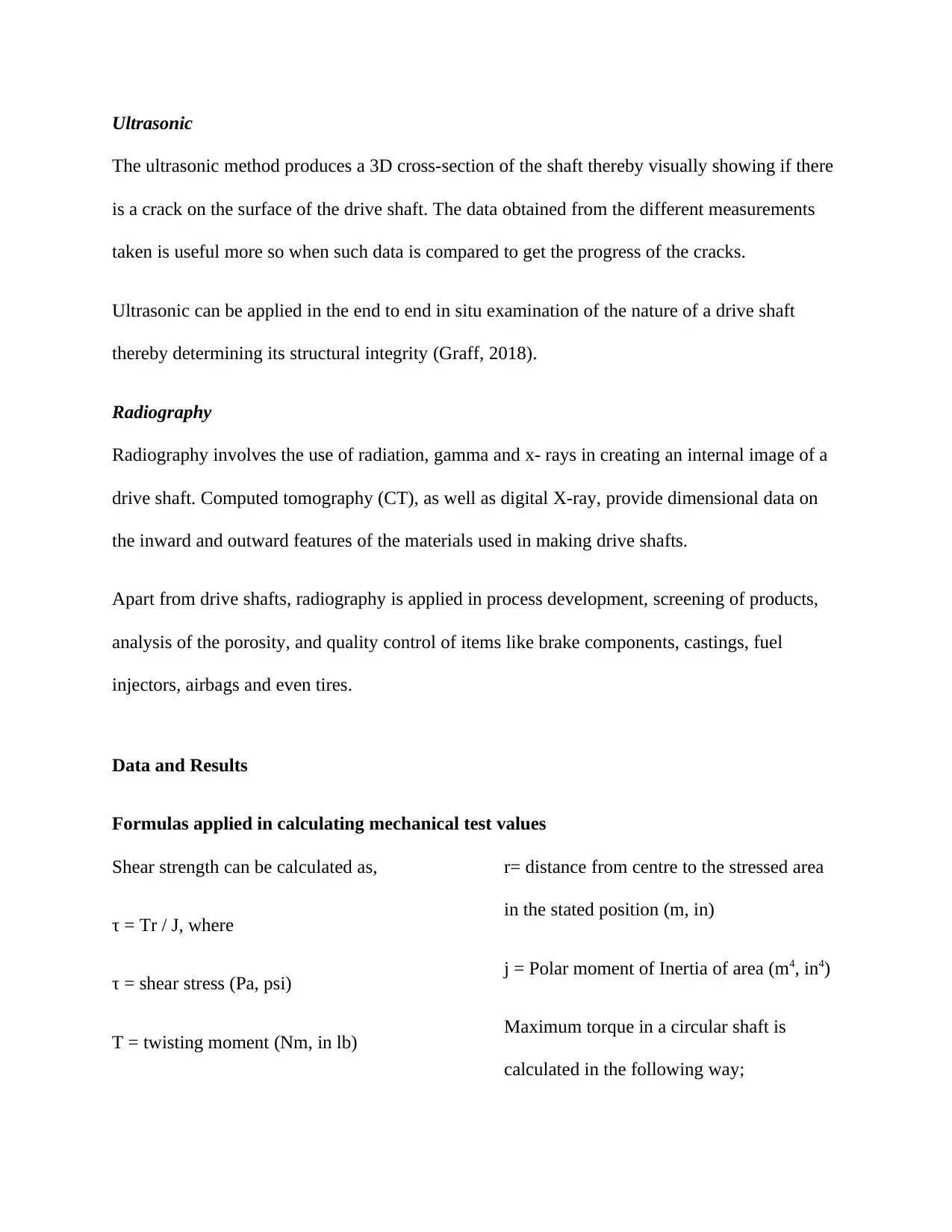
Ultrasonic
The ultrasonic method produces a 3D cross-section of the shaft thereby visually showing if there
is a crack on the surface of the drive shaft. The data obtained from the different measurements
taken is useful more so when such data is compared to get the progress of the cracks.
Ultrasonic can be applied in the end to end in situ examination of the nature of a drive shaft
thereby determining its structural integrity (Graff, 2018).
Radiography
Radiography involves the use of radiation, gamma and x- rays in creating an internal image of a
drive shaft. Computed tomography (CT), as well as digital X-ray, provide dimensional data on
the inward and outward features of the materials used in making drive shafts.
Apart from drive shafts, radiography is applied in process development, screening of products,
analysis of the porosity, and quality control of items like brake components, castings, fuel
injectors, airbags and even tires.
Data and Results
Formulas applied in calculating mechanical test values
Shear strength can be calculated as,
τ = Tr / J, where
τ = shear stress (Pa, psi)
T = twisting moment (Nm, in lb)
r= distance from centre to the stressed area
in the stated position (m, in)
j = Polar moment of Inertia of area (m4, in4)
Maximum torque in a circular shaft is
calculated in the following way;
⊘ This is a preview!⊘
Do you want full access?
Subscribe today to unlock all pages.
Trusted by 1+ million students worldwide
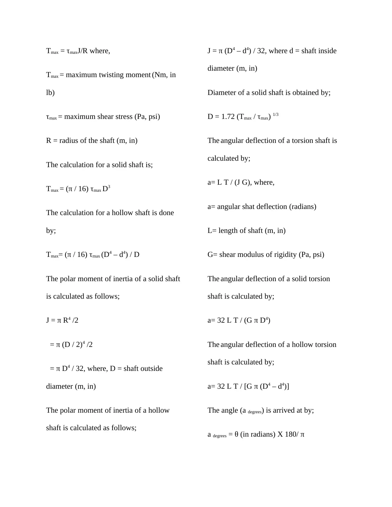
Tmax = τmaxJ/R where,
Tmax = maximum twisting moment (Nm, in
lb)
τmax = maximum shear stress (Pa, psi)
R = radius of the shaft (m, in)
The calculation for a solid shaft is;
Tmax = (π / 16) τmax D3
The calculation for a hollow shaft is done
by;
Tmax= (π / 16) τmax (D4 – d4) / D
The polar moment of inertia of a solid shaft
is calculated as follows;
J = π R4 /2
= π (D / 2)4 /2
= π D4 / 32, where, D = shaft outside
diameter (m, in)
The polar moment of inertia of a hollow
shaft is calculated as follows;
J = π (D4 – d4) / 32, where d = shaft inside
diameter (m, in)
Diameter of a solid shaft is obtained by;
D = 1.72 (Tmax / τmax) 1/3
The angular deflection of a torsion shaft is
calculated by;
a= L T / (J G), where,
a= angular shat deflection (radians)
L= length of shaft (m, in)
G= shear modulus of rigidity (Pa, psi)
The angular deflection of a solid torsion
shaft is calculated by;
a= 32 L T / (G π D4)
The angular deflection of a hollow torsion
shaft is calculated by;
a= 32 L T / [G π (D4 – d4)]
The angle (a degrees) is arrived at by;
a degrees = θ (in radians) X 180/ π
Paraphrase This Document
Need a fresh take? Get an instant paraphrase of this document with our AI Paraphraser
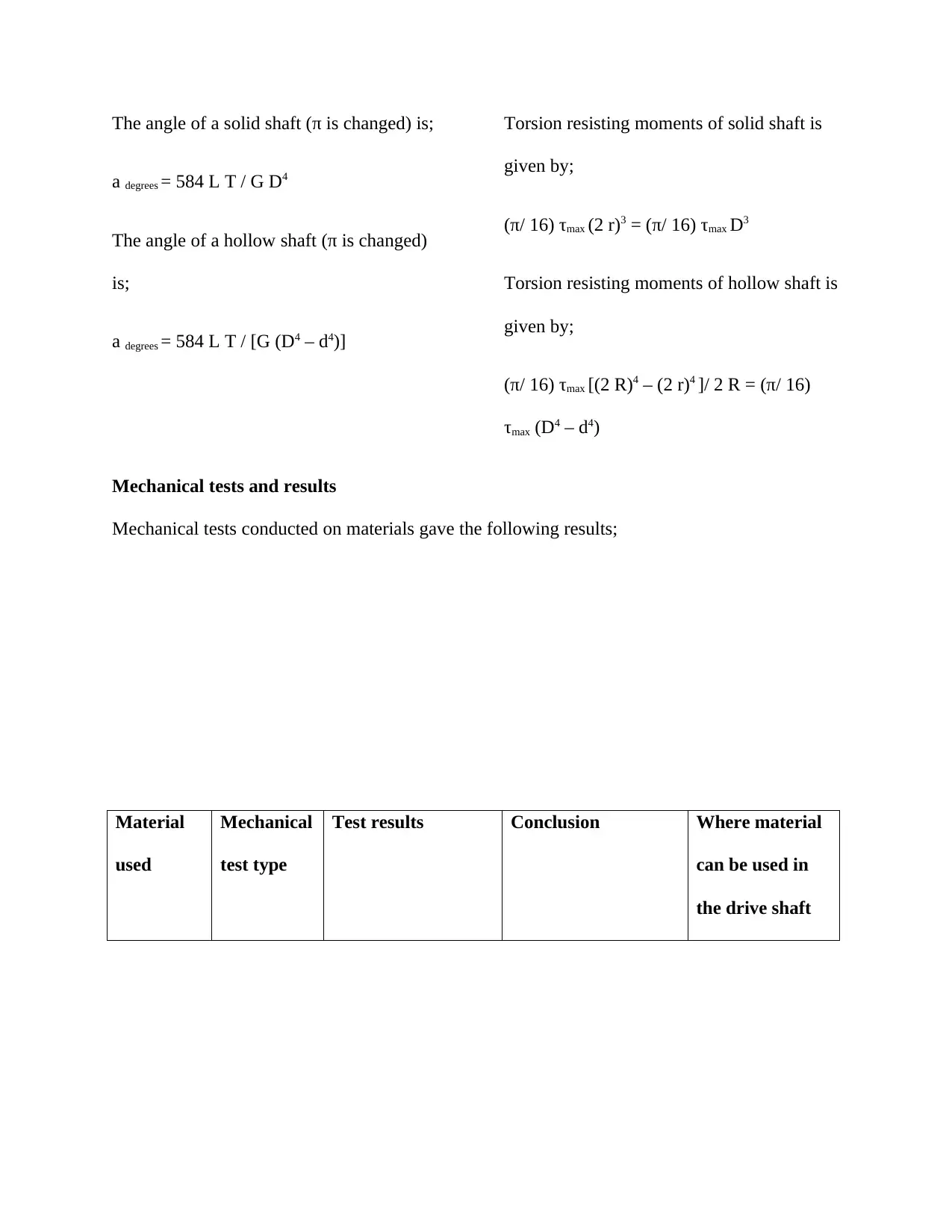
The angle of a solid shaft (π is changed) is;
a degrees = 584 L T / G D4
The angle of a hollow shaft (π is changed)
is;
a degrees = 584 L T / [G (D4 – d4)]
Torsion resisting moments of solid shaft is
given by;
(π/ 16) τmax (2 r)3 = (π/ 16) τmax D3
Torsion resisting moments of hollow shaft is
given by;
(π/ 16) τmax [(2 R)4 – (2 r)4 ]/ 2 R = (π/ 16)
τmax (D4 – d4)
Mechanical tests and results
Mechanical tests conducted on materials gave the following results;
Material
used
Mechanical
test type
Test results Conclusion Where material
can be used in
the drive shaft
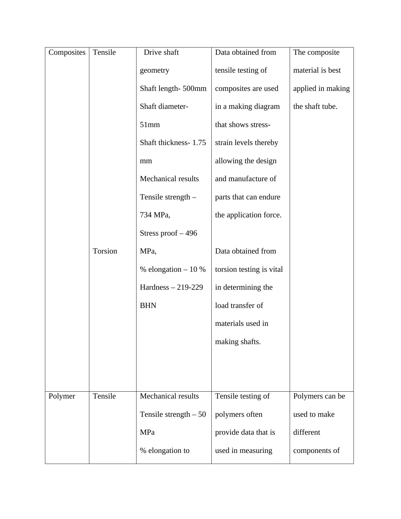
Composites Tensile
Torsion
Drive shaft
geometry
Shaft length- 500mm
Shaft diameter-
51mm
Shaft thickness- 1.75
mm
Mechanical results
Tensile strength –
734 MPa,
Stress proof – 496
MPa,
% elongation – 10 %
Hardness – 219-229
BHN
Data obtained from
tensile testing of
composites are used
in a making diagram
that shows stress-
strain levels thereby
allowing the design
and manufacture of
parts that can endure
the application force.
Data obtained from
torsion testing is vital
in determining the
load transfer of
materials used in
making shafts.
The composite
material is best
applied in making
the shaft tube.
Polymer Tensile Mechanical results
Tensile strength – 50
MPa
% elongation to
Tensile testing of
polymers often
provide data that is
used in measuring
Polymers can be
used to make
different
components of
⊘ This is a preview!⊘
Do you want full access?
Subscribe today to unlock all pages.
Trusted by 1+ million students worldwide
Torsion
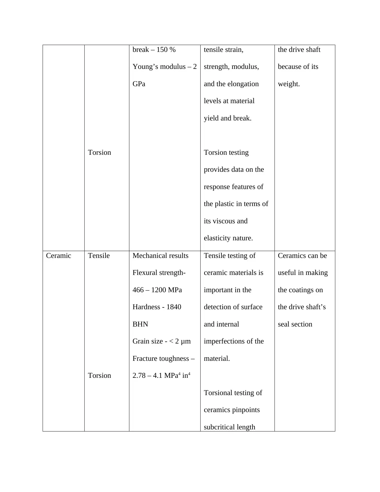
break – 150 %
Young’s modulus – 2
GPa
tensile strain,
strength, modulus,
and the elongation
levels at material
yield and break.
Torsion testing
provides data on the
response features of
the plastic in terms of
its viscous and
elasticity nature.
the drive shaft
because of its
weight.
Ceramic Tensile
Torsion
Mechanical results
Flexural strength-
466 – 1200 MPa
Hardness - 1840
BHN
Grain size - < 2 μm
Fracture toughness –
2.78 – 4.1 MPa4 in4
Tensile testing of
ceramic materials is
important in the
detection of surface
and internal
imperfections of the
material.
Torsional testing of
ceramics pinpoints
subcritical length
Ceramics can be
useful in making
the coatings on
the drive shaft’s
seal section
Paraphrase This Document
Need a fresh take? Get an instant paraphrase of this document with our AI Paraphraser
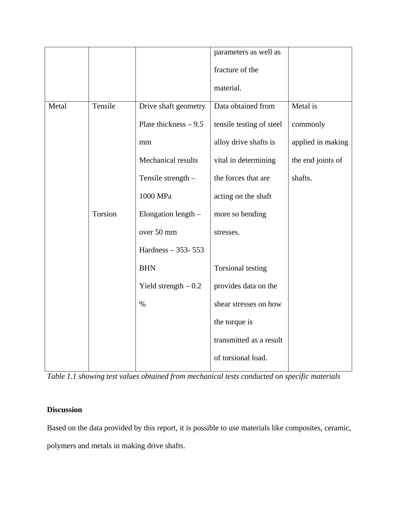
parameters as well as
fracture of the
material.
Metal Tensile
Torsion
Drive shaft geometry
Plate thickness – 9.5
mm
Mechanical results
Tensile strength –
1000 MPa
Elongation length –
over 50 mm
Hardness – 353- 553
BHN
Yield strength – 0.2
%
Data obtained from
tensile testing of steel
alloy drive shafts is
vital in determining
the forces that are
acting on the shaft
more so bending
stresses.
Torsional testing
provides data on the
shear stresses on how
the torque is
transmitted as a result
of torsional load.
Metal is
commonly
applied in making
the end joints of
shafts.
Table 1.1 showing test values obtained from mechanical tests conducted on specific materials
Discussion
Based on the data provided by this report, it is possible to use materials like composites, ceramic,
polymers and metals in making drive shafts.
The metal alloys are the best to use when making drive shafts as they possess better mechanical
properties than the other materials.
Conclusion
The testing of materials used in making drive shaft is important in knowing the best material to
use in production. Currently, the world has opened the window for new possibilities allowing
new production methods using better materials. It is important that the material used in making
drive shafts prove its worthiness bypassing all the relevant tests.
Failure in Cosmetic fittings
Abstract
Cosmetic fittings are automotive parts that enhance the customization, comfort, safety,
convenience and performance of the automobiles and they tend to be added on to add the visual
beauty of the motor vehicle. The rate of growth of the automotive sector is high due to the new
innovations that meet the demands of the customers. Cosmetic fittings appear on this list of
innovations as they not only add beauty features but also vehicle performance.
Introduction
The automotive sector is currently experiencing new constant challenges caused by the ever-
rising need for super quality and cheap automotive components and fittings. The engineers
should be very keen when designing and manufacturing these fittings so that they are capable of
withstanding the selected environments in which they are to be put. It is vital to use systematic
analysis in determining the occurrence of any failures and suggest the best ways of producing
⊘ This is a preview!⊘
Do you want full access?
Subscribe today to unlock all pages.
Trusted by 1+ million students worldwide
1 out of 21
Related Documents


Your All-in-One AI-Powered Toolkit for Academic Success.
+13062052269
info@desklib.com
Available 24*7 on WhatsApp / Email
![[object Object]](/_next/static/media/star-bottom.7253800d.svg)
Unlock your academic potential
Copyright © 2020–2026 A2Z Services. All Rights Reserved. Developed and managed by ZUCOL.