Modeling, Analysis, and Simulation of a Dual Rotor Wind Turbine
VerifiedAdded on 2022/10/17
|10
|5219
|20
Report
AI Summary
This document is a research proposal for a Master's project in Mechanical Engineering Technology. It focuses on the modeling, simulation, and optimization of a single shaft co-rotating dual rotor wind turbine. The study aims to create a mathematical model using MATLAB/Simulink to analyze the turbine's performance, considering mechanical, aerodynamic, and electrical components, including a permanent magnet synchronous generator (PMSG). The proposal investigates the impact of wind speed variations, specifically the deceleration of wind after the front rotor, on the power output of the rear rotor. Different pitch angles for the rear rotor blades are also considered to assess their effect on overall power generation. The research seeks to provide insights into the efficiency gains of dual rotor wind turbines compared to single rotor designs, addressing the challenges of wind energy harvesting and proposing potential improvements in turbine performance. The report discusses the derivation of mechanical and aerodynamic models, emphasizing the importance of accurate simulations for performance prediction and analysis.
http://www.iaeme.com/IJMET/index.asp 897 editor@iaeme.com
International Journal of Mechanical Engineering and Technology (IJMET)
Volume 9, Issue 9, September 2018, pp. 897–906, Article ID: IJMET_09_09_099
Available online at http://www.iaeme.com/ijmet/issues.asp?JType=IJMET&VType=9&IType=9
ISSN Print: 0976-6340 and ISSN Online: 0976-6359
© IAEME Publication Scopus Indexed
MODELING AND ANALYSIS OF A SINGLE
SHAFT CO-ROTATING DUAL ROTOR SMALL
WIND TURBINE
Ercan Erturk
Bahcesehir University, Mechatronics Engineering Department
Besiktas, Istanbul, Turkey
Orhan Gokcol
Bahcesehir University, Computer Education and Instructional Technologies Department
Besiktas, Istanbul, Turkey
Selim Sivrioglu and Fevzi Cakmak Bolat
Gebze Technical University, Mechanical Engineering Department
Gebze, Kocaeli, Turkey
ABSTRACT
Dual rotor wind turbines have higher efficiency and compared to single rotor wind
turbines they can harvest more energy from the wind. In the present study a single
shaft co-rotating dual rotor wind turbine is modelled with mechanical, aerodynamical
and electrical components. The considered model includes a permanent magnet
synchronous generator (PMSG). In a dual rotor wind turbine, after the front rotor the
wind speed is decreased since the front rotor extracts some portion of energy from the
wind. The wind with reduced speed downstream of the front rotor acts as an inflow for
the rear rotor. The amount of decrease in the wind speed downstream of the front
rotor affects the power output of the dual rotor wind turbine. The mechanical
dynamics, the aerodynamic power and also the electrical power of the single shaft co-
rotating dual rotor wind turbine are simulated using MATLAB/Simulink software.
Key words: Dual rotor wind turbine, co-rotating wind turbine, wind energy,
permanent magnet synchronous generator.
Cite this Article: Ercan Erturk, Orhan Gokcol, Selim Sivrioglu and Fevzi Cakmak
Bolat, Modeling and Analysis of a Single Shaft Co-Rotating Dual Rotor Small Wind
Turbine, International Journal of Mechanical Engineering and Technology 9(9),
2018, pp. 897–906.
http://www.iaeme.com/IJMET/issues.asp?JType=IJMET&VType=9&IType=9
Paraphrase This Document
Need a fresh take? Get an instant paraphrase of this document with our AI Paraphraser
Modeling and Analysis of a Single Shaft Co-Rotating Dual Rotor Small Wind Turbine
http://www.iaeme.com/IJMET/index.asp 898 editor@iaeme.com
1. INTRODUCTION
Wind is clean, renewable, inexhaustible free energy source for electric power generation. The
extracted energy from a wind turbine depends on the wind speed, therefore it is economically
more profitable to install the wind turbines at regions where the wind power density is high.
The extracted energy from a wind turbine also depends on the efficiency of the wind turbine.
Today with the use of better design and analysis softwares and also with the use of better
manufacturing techniques, most of the wind turbines have efficiencies more or less close to
each other with very small differences. If we can increase the efficiency of wind turbines
furthermore not only we would be able to extract more energy from the wind at regions with
high power density but also it would be economically feasible to install wind turbines at
regions with less wind power densities.
Wind turbines that have two rotors, one at the front and one at the rear of the wind turbine,
offers high efficiency [1]. A single rotor wind turbine theoretically can extract maximum
59.3% of the energy available in the wind [2] and this limit is known as the Betz limit. Using
multiple actuator-disk theory one can easily show that a dual rotor wind turbine theoretically
can extract maximum 64% of the energy available in the wind [3]. Therefore, the maximum
energy that a dual rotor wind turbine can theoretically extract from the wind is 8% higher than
that of a single rotor wind turbine.
In the literature it is possible to find many numerical and experimental studies that shows
the efficiency of dual rotor wind turbines. Among these studies, Shen et al. [4] have simulated
a Nordtank 500 kW wind turbine using Actuator Line technique implemented EllipSys3D
Navier-Stokes solver. They [4] have considered the Nordtank 500 kW wind turbine both
having a single rotor and also having a counter rotating dual rotor. Using the real wind data
measurements taken on the island of Spragø in Denmark, they have concluded that a dual
rotor wind turbine can produce 43.5% more energy annually compared to a single rotor wind
turbine.
Habash et al. [5] and Mitulet et al. [6] have performed wind tunnel experiments on dual
rotor wind turbines. Their [5,6] results indicate that a dual rotor wind turbine can produce
60% more energy than a single rotor wind turbine.
In their study, Jung et al. [7] have designed, built and tested a 30 kW dual rotor wind
turbine. In this wind turbine, the motions of both rotors are combined with a gear system with
bevel gears and planet gears and transmitted perpendicular to an electric generator. After the
actual field tests, they [7] stated that the power coefficient of this dual rotor wind turbine is
around 0.5, which is well above the power coefficients of single rotor wind turbines.
These different type of studies, numerical [4], experimental [5,6] and field studies [7] all
reported that dual-rotor wind turbines have efficiencies around 45-50% which is much greater
than that of single rotor wind turbines.
In an experimental study using PIV measurements Ozbay et al. [8] have compared the
single rotor wind turbines with dual rotor wind turbines having two rotors rotating in co- and
counter-directions in order to investigate the effect of the direction of the rotation of the two
rotors on the power extracted from the wind. Ozbay et al. [8] state that a co-rotating dual rotor
wind turbine can generate 48% more power compared to a single rotor wind turbine. The
increase in the generated power when two rotors are used is remarkable.
In order to maximize the efficiency of the wind turbines while minimizing the loads, wind
turbines are operated under control. Since in nature the wind has continuously changing
characteristics with continuously varying wind speeds, the aerodynamic torque and/or power
of the wind turbine is controlled by changing the pitch angle of the wind turbine blades.
Control of wind turbine blades also becomes very important at high wind speeds in variable
Ercan Erturk, Orhan Gokcol, Selim Sivrioglu and Fevzi Cakmak Bolat
http://www.iaeme.com/IJMET/index.asp 899 editor@iaeme.com
speed wind turbines [9]. Linear, nonlinear and intelligent control methods for various wind
turbine systems have been studied by many researchers [10,11,12].
In the literature, No et al. [13] and Farahani et al. [14] studied modeling of counter-
rotating dual rotor wind turbines. In the studies of No et al. [13] and Farahani et al. [14] the
counter motions of the wind turbine rotors are combined into a single rotational shaft motion
by set of gears which then rotates the generator shaft as the same with that of Jung et al. [6].
The mechanical design, the physics and also modeling of a single shaft co-rotating dual rotor
wind turbine is completely different than that of dual rotor wind turbine considered in No et
al. [13] and Farahani et al. [14]. To the best of our knowledge, in the literature there is no
study that attempts to model and simulate a single shaft co-rotating dual rotor wind turbine
this constitutes the main motivation of this study. In order to reliably predict and analyze the
performance of dual rotor wind turbine, it is important to have an accurate and reliable model.
In a dual rotor wind turbine, the wind first passes over the front rotor blades and loses
some portion of its energy. Then downstream of the front rotor, the residual wind with lower
energy passes over the rear rotor blades and loses some portion of its energy again. As one
can imagine, since not only the aerodynamics but also the whole system of dual rotor wind
turbines are much more complex compared to single rotor wind turbines. In their analysis No
et al. [13] and Farahani et al. [14] assumed that the flow is uniform downstream of the front
rotor and upstream of the rear rotor, i.e. between the two rotors. Most probably this
assumption introduces some errors in the aerodynamic part of their simulation model.
However, for dual rotor wind turbines since there is no better aerodynamic approximation in
the literature for the flow between the two rotors of the dual rotor wind turbine, in this study,
following No et al. [13] and Farahani et al. [14] we will also assume that the flow approaching
to the rear rotor is uniform.
We note that the rotational speed and the pitching angle of the front rotor blades affect the
speed of the flow downstream of the front rotor. The rotational speed of the front rotor and the
pitching angle of the front rotor blades can change dynamically during operation of the wind
turbine depending on the incoming wind speed and the wind turbine control algorithm.
Therefore, the wind speed approaching the rear rotor varies during operation of dual rotor
wind turbine. In this study, we will examine the variation of the power output of the rear
rotor, i.e. therefore the total power output of the dual rotor wind turbine, as a function of the
flow speed downstream of the front rotor. For this we will assume different deceleration of
the wind after the front rotor and calculate the total power output of the dual rotor wind
turbine and obtain the variation of the total power as a function of deceleration. The power
output of the rear rotor, i.e. therefore the total power output of the dual rotor wind turbine, is
also a function of the rear rotor blade pitch angle. In this study we will also examine the effect
of the rear rotor blade pitch angle on the total power output by using various pitch angles for
the rear rotor blades.
The aim of this study is then to derive a mathematical model for a single shaft co-rotating
dual rotor wind turbine in MATLAB/Simulink environment. Using this mathematical model,
the power output of the wind turbine is investigated for different pitch angles of the rear rotor
blades in a dual rotor wind turbine. Different case studies are realized in order to analyze the
total power output of the dual rotor turbine model for different deceleration values of the wind
downstream of the first rotor.
2. DERIVATION OF MECHANICAL MODEL
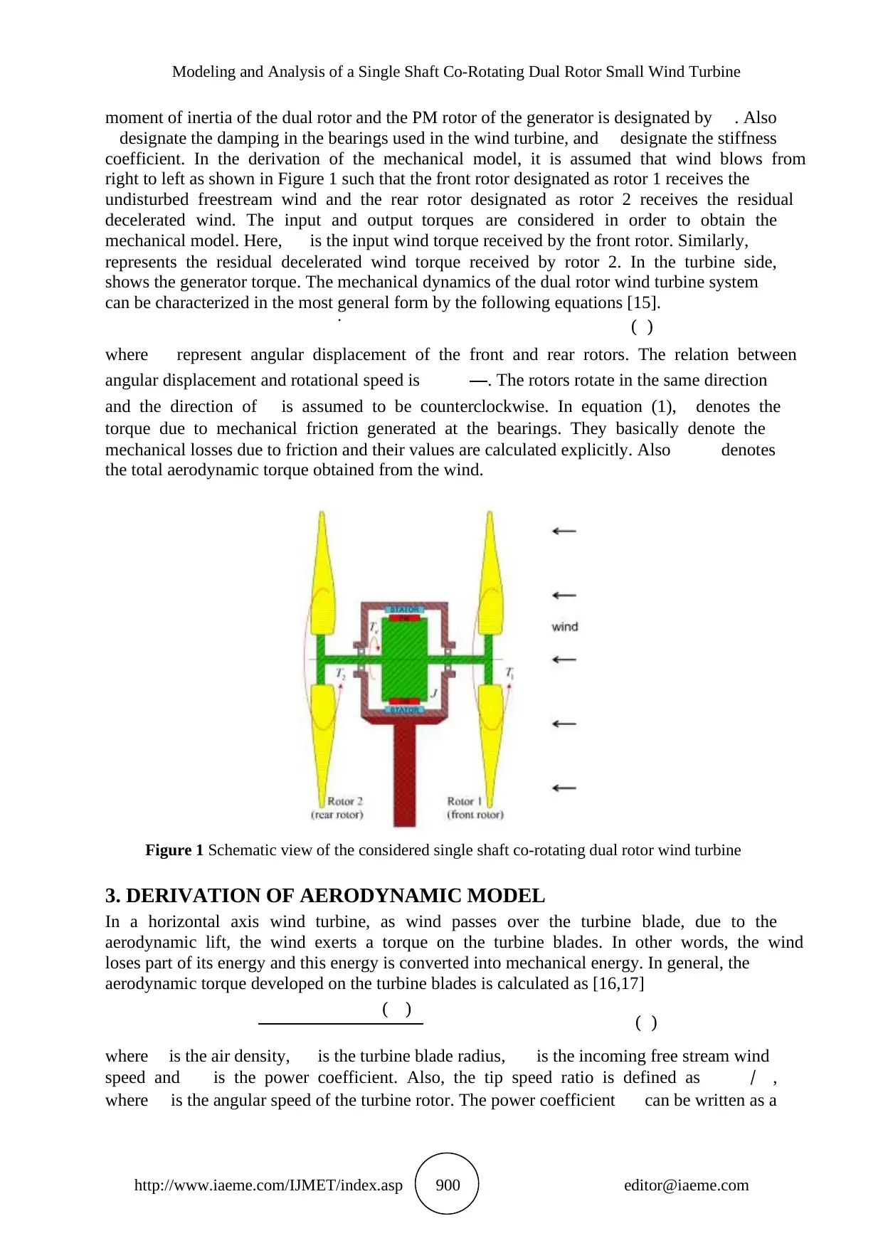
The structure of the considered co-rotating dual rotor wind turbine is schematically shown in
Figure 1 as a cross section view. As seen in this figure, the turbine has two co-rotating rotors
connected to the PM rotor with a single shaft. The rotational speed of the rotor is. The
http://www.iaeme.com/IJMET/index.asp 899 editor@iaeme.com
speed wind turbines [9]. Linear, nonlinear and intelligent control methods for various wind
turbine systems have been studied by many researchers [10,11,12].
In the literature, No et al. [13] and Farahani et al. [14] studied modeling of counter-
rotating dual rotor wind turbines. In the studies of No et al. [13] and Farahani et al. [14] the
counter motions of the wind turbine rotors are combined into a single rotational shaft motion
by set of gears which then rotates the generator shaft as the same with that of Jung et al. [6].
The mechanical design, the physics and also modeling of a single shaft co-rotating dual rotor
wind turbine is completely different than that of dual rotor wind turbine considered in No et
al. [13] and Farahani et al. [14]. To the best of our knowledge, in the literature there is no
study that attempts to model and simulate a single shaft co-rotating dual rotor wind turbine
this constitutes the main motivation of this study. In order to reliably predict and analyze the
performance of dual rotor wind turbine, it is important to have an accurate and reliable model.
In a dual rotor wind turbine, the wind first passes over the front rotor blades and loses
some portion of its energy. Then downstream of the front rotor, the residual wind with lower
energy passes over the rear rotor blades and loses some portion of its energy again. As one
can imagine, since not only the aerodynamics but also the whole system of dual rotor wind
turbines are much more complex compared to single rotor wind turbines. In their analysis No
et al. [13] and Farahani et al. [14] assumed that the flow is uniform downstream of the front
rotor and upstream of the rear rotor, i.e. between the two rotors. Most probably this
assumption introduces some errors in the aerodynamic part of their simulation model.
However, for dual rotor wind turbines since there is no better aerodynamic approximation in
the literature for the flow between the two rotors of the dual rotor wind turbine, in this study,
following No et al. [13] and Farahani et al. [14] we will also assume that the flow approaching
to the rear rotor is uniform.
We note that the rotational speed and the pitching angle of the front rotor blades affect the
speed of the flow downstream of the front rotor. The rotational speed of the front rotor and the
pitching angle of the front rotor blades can change dynamically during operation of the wind
turbine depending on the incoming wind speed and the wind turbine control algorithm.
Therefore, the wind speed approaching the rear rotor varies during operation of dual rotor
wind turbine. In this study, we will examine the variation of the power output of the rear
rotor, i.e. therefore the total power output of the dual rotor wind turbine, as a function of the
flow speed downstream of the front rotor. For this we will assume different deceleration of
the wind after the front rotor and calculate the total power output of the dual rotor wind
turbine and obtain the variation of the total power as a function of deceleration. The power
output of the rear rotor, i.e. therefore the total power output of the dual rotor wind turbine, is
also a function of the rear rotor blade pitch angle. In this study we will also examine the effect
of the rear rotor blade pitch angle on the total power output by using various pitch angles for
the rear rotor blades.
The aim of this study is then to derive a mathematical model for a single shaft co-rotating
dual rotor wind turbine in MATLAB/Simulink environment. Using this mathematical model,
the power output of the wind turbine is investigated for different pitch angles of the rear rotor
blades in a dual rotor wind turbine. Different case studies are realized in order to analyze the
total power output of the dual rotor turbine model for different deceleration values of the wind
downstream of the first rotor.
2. DERIVATION OF MECHANICAL MODEL
The structure of the considered co-rotating dual rotor wind turbine is schematically shown in
Figure 1 as a cross section view. As seen in this figure, the turbine has two co-rotating rotors
connected to the PM rotor with a single shaft. The rotational speed of the rotor is. The
⊘ This is a preview!⊘
Do you want full access?
Subscribe today to unlock all pages.
Trusted by 1+ million students worldwide
Modeling and Analysis of a Single Shaft Co-Rotating Dual Rotor Small Wind Turbine
http://www.iaeme.com/IJMET/index.asp 900 editor@iaeme.com
moment of inertia of the dual rotor and the PM rotor of the generator is designated by . Also
designate the damping in the bearings used in the wind turbine, and designate the stiffness
coefficient. In the derivation of the mechanical model, it is assumed that wind blows from
right to left as shown in Figure 1 such that the front rotor designated as rotor 1 receives the
undisturbed freestream wind and the rear rotor designated as rotor 2 receives the residual
decelerated wind. The input and output torques are considered in order to obtain the
mechanical model. Here, is the input wind torque received by the front rotor. Similarly,
represents the residual decelerated wind torque received by rotor 2. In the turbine side,
shows the generator torque. The mechanical dynamics of the dual rotor wind turbine system
can be characterized in the most general form by the following equations [15].̇
( )
where represent angular displacement of the front and rear rotors. The relation between
angular displacement and rotational speed is . The rotors rotate in the same direction
and the direction of is assumed to be counterclockwise. In equation (1), denotes the
torque due to mechanical friction generated at the bearings. They basically denote the
mechanical losses due to friction and their values are calculated explicitly. Also denotes
the total aerodynamic torque obtained from the wind.
Figure 1 Schematic view of the considered single shaft co-rotating dual rotor wind turbine
3. DERIVATION OF AERODYNAMIC MODEL
In a horizontal axis wind turbine, as wind passes over the turbine blade, due to the
aerodynamic lift, the wind exerts a torque on the turbine blades. In other words, the wind
loses part of its energy and this energy is converted into mechanical energy. In general, the
aerodynamic torque developed on the turbine blades is calculated as [16,17]
( ) ( )
where is the air density, is the turbine blade radius, is the incoming free stream wind
speed and is the power coefficient. Also, the tip speed ratio is defined as ⁄ ,
where is the angular speed of the turbine rotor. The power coefficient can be written as a
Paraphrase This Document
Need a fresh take? Get an instant paraphrase of this document with our AI Paraphraser
Ercan Erturk, Orhan Gokcol, Selim Sivrioglu and Fevzi Cakmak Bolat
http://www.iaeme.com/IJMET/index.asp 901 editor@iaeme.com
function of the blade pitch angle and variable. In this study, for the aerodynamic model
the following equations are used
( )
( )
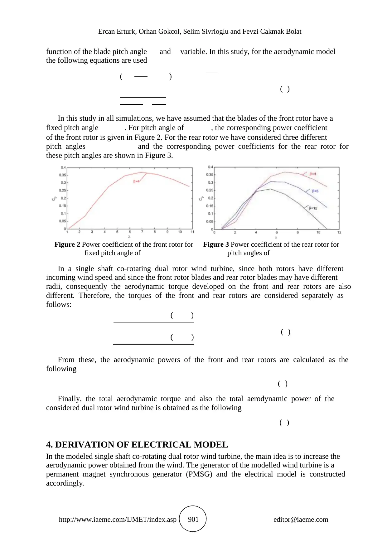
In this study in all simulations, we have assumed that the blades of the front rotor have a
fixed pitch angle . For pitch angle of , the corresponding power coefficient
of the front rotor is given in Figure 2. For the rear rotor we have considered three different
pitch angles and the corresponding power coefficients for the rear rotor for
these pitch angles are shown in Figure 3.
Figure 2 Power coefficient of the front rotor for
fixed pitch angle of
Figure 3 Power coefficient of the rear rotor for
pitch angles of
In a single shaft co-rotating dual rotor wind turbine, since both rotors have different
incoming wind speed and since the front rotor blades and rear rotor blades may have different
radii, consequently the aerodynamic torque developed on the front and rear rotors are also
different. Therefore, the torques of the front and rear rotors are considered separately as
follows:
( )
( ) ( )
From these, the aerodynamic powers of the front and rear rotors are calculated as the
following
( )
Finally, the total aerodynamic torque and also the total aerodynamic power of the
considered dual rotor wind turbine is obtained as the following
( )
4. DERIVATION OF ELECTRICAL MODEL
In the modeled single shaft co-rotating dual rotor wind turbine, the main idea is to increase the
aerodynamic power obtained from the wind. The generator of the modelled wind turbine is a
permanent magnet synchronous generator (PMSG) and the electrical model is constructed
accordingly.
http://www.iaeme.com/IJMET/index.asp 901 editor@iaeme.com
function of the blade pitch angle and variable. In this study, for the aerodynamic model
the following equations are used
( )
( )
In this study in all simulations, we have assumed that the blades of the front rotor have a
fixed pitch angle . For pitch angle of , the corresponding power coefficient
of the front rotor is given in Figure 2. For the rear rotor we have considered three different
pitch angles and the corresponding power coefficients for the rear rotor for
these pitch angles are shown in Figure 3.
Figure 2 Power coefficient of the front rotor for
fixed pitch angle of
Figure 3 Power coefficient of the rear rotor for
pitch angles of
In a single shaft co-rotating dual rotor wind turbine, since both rotors have different
incoming wind speed and since the front rotor blades and rear rotor blades may have different
radii, consequently the aerodynamic torque developed on the front and rear rotors are also
different. Therefore, the torques of the front and rear rotors are considered separately as
follows:
( )
( ) ( )
From these, the aerodynamic powers of the front and rear rotors are calculated as the
following
( )
Finally, the total aerodynamic torque and also the total aerodynamic power of the
considered dual rotor wind turbine is obtained as the following
( )
4. DERIVATION OF ELECTRICAL MODEL
In the modeled single shaft co-rotating dual rotor wind turbine, the main idea is to increase the
aerodynamic power obtained from the wind. The generator of the modelled wind turbine is a
permanent magnet synchronous generator (PMSG) and the electrical model is constructed
accordingly.
Modeling and Analysis of a Single Shaft Co-Rotating Dual Rotor Small Wind Turbine
http://www.iaeme.com/IJMET/index.asp 902 editor@iaeme.com
The dynamic model of PMSG is derived from the two-phase synchronous reference frame
in which the q-axis is ahead of the d-axis with respect to the direction of the rotation. The
equations are given as [17,18,19]
( )
( ) ( )
where are component of the stator voltages and currents. Also, is armature
resistance, is magnetic flux, and are inductances of the generator at and axes.
Assuming that the equations (12) and (13) become
( )
( ) ( )
In general, the electromagnetic torque is defined as
(( ) ) ( )
Since the inductance of the generator is accepted as , then the
electromagnetic torque becomes
( )
where represents the pole pairs. The electrical rotating speed is defined as
( )
The electrical power of the generator due to the motion of the front and rear rotors is
defined as the following
( )
3. SIMULATION RESULTS AND DISCUSSIONS
According to the Betz Law, an ideal wind turbine will decelerate the wind by 2/3 of its
original speed. In other words, the wind speed at far away downstream of an ideal wind
turbine is equal to 1/3 of the freestream wind speed at far away upstream of the wind turbine.
Also, for an ideal wind turbine, the wind speed at the plane of the rotor is equal to the 2/3 of
the freestream wind speed at far away upstream of the wind turbine, thus the wind speed right
after the rotor is equal to 0.67 of the incoming freestream wind speed. Also, the Betz analysis
is valid only for deceleration values of 50% or above at the plane of the rotor. In other words,
for the Betz analysis to be valid, the wind speed right after the rotor can be minimum equal to
0.5 of the incoming freestream wind speed. We note that these numbers are valid only for an
ideal wind turbine and in real applications the wind does not decelerate to the ideal limit. For
most modern wind turbine blades the axial induction coefficient is less than 0.3 along the
blade.
In order to analyze and simulate the rear rotor we need to specify the residual wind speed
downstream of the front rotor that is to say we need to specify the wind speed upstream of the
rear rotor. Following No et al. [13] and Farahani et al. [14] we will assume that the flow
approaching to the rear rotor is uniform. According to the Betz law the wind speed after the
front rotor should be greater than 0.5 of the incoming wind speed. Therefore, in this study we
will assume different values for the residual wind speed incoming to the rear rotor after the
⊘ This is a preview!⊘
Do you want full access?
Subscribe today to unlock all pages.
Trusted by 1+ million students worldwide
Ercan Erturk, Orhan Gokcol, Selim Sivrioglu and Fevzi Cakmak Bolat
http://www.iaeme.com/IJMET/index.asp 903 editor@iaeme.com
front rotor and run the simulation for these different deceleration values in order to see the
effect of the residual wind speed on the power output of the simulated dual rotor wind turbine.
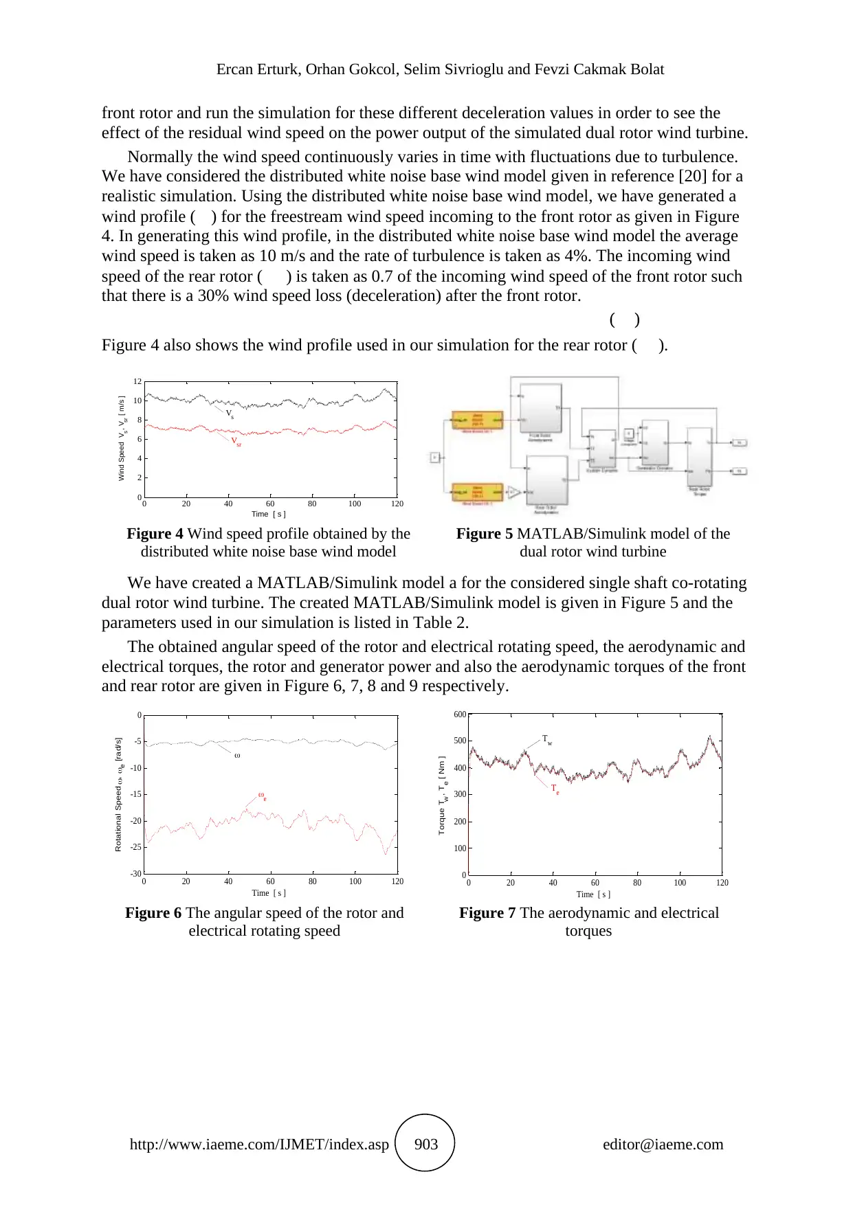
Normally the wind speed continuously varies in time with fluctuations due to turbulence.
We have considered the distributed white noise base wind model given in reference [20] for a
realistic simulation. Using the distributed white noise base wind model, we have generated a
wind profile ( ) for the freestream wind speed incoming to the front rotor as given in Figure
4. In generating this wind profile, in the distributed white noise base wind model the average
wind speed is taken as 10 m/s and the rate of turbulence is taken as 4%. The incoming wind
speed of the rear rotor ( ) is taken as 0.7 of the incoming wind speed of the front rotor such
that there is a 30% wind speed loss (deceleration) after the front rotor.
( )
Figure 4 also shows the wind profile used in our simulation for the rear rotor ( ).
Figure 4 Wind speed profile obtained by the
distributed white noise base wind model
Figure 5 MATLAB/Simulink model of the
dual rotor wind turbine
We have created a MATLAB/Simulink model a for the considered single shaft co-rotating
dual rotor wind turbine. The created MATLAB/Simulink model is given in Figure 5 and the
parameters used in our simulation is listed in Table 2.
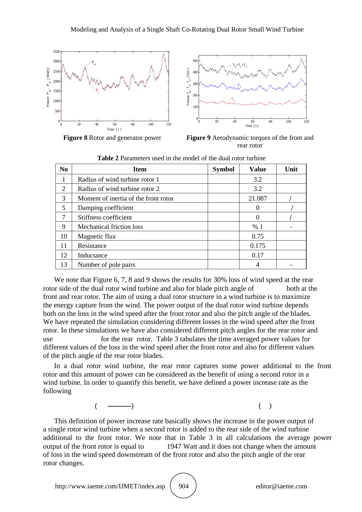
The obtained angular speed of the rotor and electrical rotating speed, the aerodynamic and
electrical torques, the rotor and generator power and also the aerodynamic torques of the front
and rear rotor are given in Figure 6, 7, 8 and 9 respectively.
Figure 6 The angular speed of the rotor and
electrical rotating speed
Figure 7 The aerodynamic and electrical
torques
0 20 40 60 80 100 120
0
2
4
6
8
10
12
Time [ s ]
Wind Speed Vs, Vsr [ m/s ]
Vsr
Vs
0 20 40 60 80 100 120
-30
-25
-20
-15
-10
-5
0
Time [ s ]
Rotational Speed , e [rad/s]
e
0 20 40 60 80 100 120
0
100
200
300
400
500
600
Time [ s ]
Torque T
w , T
e [ Nm ]
T w
T e
http://www.iaeme.com/IJMET/index.asp 903 editor@iaeme.com
front rotor and run the simulation for these different deceleration values in order to see the
effect of the residual wind speed on the power output of the simulated dual rotor wind turbine.
Normally the wind speed continuously varies in time with fluctuations due to turbulence.
We have considered the distributed white noise base wind model given in reference [20] for a
realistic simulation. Using the distributed white noise base wind model, we have generated a
wind profile ( ) for the freestream wind speed incoming to the front rotor as given in Figure
4. In generating this wind profile, in the distributed white noise base wind model the average
wind speed is taken as 10 m/s and the rate of turbulence is taken as 4%. The incoming wind
speed of the rear rotor ( ) is taken as 0.7 of the incoming wind speed of the front rotor such
that there is a 30% wind speed loss (deceleration) after the front rotor.
( )
Figure 4 also shows the wind profile used in our simulation for the rear rotor ( ).
Figure 4 Wind speed profile obtained by the
distributed white noise base wind model
Figure 5 MATLAB/Simulink model of the
dual rotor wind turbine
We have created a MATLAB/Simulink model a for the considered single shaft co-rotating
dual rotor wind turbine. The created MATLAB/Simulink model is given in Figure 5 and the
parameters used in our simulation is listed in Table 2.
The obtained angular speed of the rotor and electrical rotating speed, the aerodynamic and
electrical torques, the rotor and generator power and also the aerodynamic torques of the front
and rear rotor are given in Figure 6, 7, 8 and 9 respectively.
Figure 6 The angular speed of the rotor and
electrical rotating speed
Figure 7 The aerodynamic and electrical
torques
0 20 40 60 80 100 120
0
2
4
6
8
10
12
Time [ s ]
Wind Speed Vs, Vsr [ m/s ]
Vsr
Vs
0 20 40 60 80 100 120
-30
-25
-20
-15
-10
-5
0
Time [ s ]
Rotational Speed , e [rad/s]
e
0 20 40 60 80 100 120
0
100
200
300
400
500
600
Time [ s ]
Torque T
w , T
e [ Nm ]
T w
T e
Paraphrase This Document
Need a fresh take? Get an instant paraphrase of this document with our AI Paraphraser
Modeling and Analysis of a Single Shaft Co-Rotating Dual Rotor Small Wind Turbine
http://www.iaeme.com/IJMET/index.asp 904 editor@iaeme.com
Figure 8 Rotor and generator power Figure 9 Aerodynamic torques of the front and
rear rotor
Table 2 Parameters used in the model of the dual rotor turbine
No Item Symbol Value Unit
1 Radius of wind turbine rotor 1 3.2
2 Radius of wind turbine rotor 2 3.2
3 Moment of inertia of the front rotor 21.087 ⁄
5 Damping coefficient 0 ⁄
7 Stiffness coefficient 0 ⁄
9 Mechanical friction loss % 1 -
10 Magnetic flux 0.75
11 Resistance 0.175
12 Inductance 0.17
13 Number of pole pairs 4 -
We note that Figure 6, 7, 8 and 9 shows the results for 30% loss of wind speed at the rear
rotor side of the dual rotor wind turbine and also for blade pitch angle of both at the
front and rear rotor. The aim of using a dual rotor structure in a wind turbine is to maximize
the energy capture from the wind. The power output of the dual rotor wind turbine depends
both on the loss in the wind speed after the front rotor and also the pitch angle of the blades.
We have repeated the simulation considering different losses in the wind speed after the front
rotor. In these simulations we have also considered different pitch angles for the rear rotor and
use for the rear rotor. Table 3 tabulates the time averaged power values for
different values of the loss in the wind speed after the front rotor and also for different values
of the pitch angle of the rear rotor blades.
In a dual rotor wind turbine, the rear rotor captures some power additional to the front
rotor and this amount of power can be considered as the benefit of using a second rotor in a
wind turbine. In order to quantify this benefit, we have defined a power increase rate as the
following
( ) ( )
This definition of power increase rate basically shows the increase in the power output of
a single rotor wind turbine when a second rotor is added to the rear side of the wind turbine
additional to the front rotor. We note that in Table 3 in all calculations the average power
output of the front rotor is equal to 1947 Watt and it does not change when the amount
of loss in the wind speed downstream of the front rotor and also the pitch angle of the rear
rotor changes.
0 20 40 60 80 100 120
0
500
1000
1500
2000
2500
3000
3500
Time [ s ]
Power P w , P e [ Watt ]
P e
P w
0 20 40 60 80 100 120
0
100
200
300
400
500
Time [ s ]
Torque T
w , T
1 , T
2 [ Nm ]
T 1
T 2
T w
=T 1 +T 2
Ercan Erturk, Orhan Gokcol, Selim Sivrioglu and Fevzi Cakmak Bolat
http://www.iaeme.com/IJMET/index.asp 905 editor@iaeme.com
Table 3 Power increase with respect to rear side wind speed loss
Rear
side
wind
speed
loss
Generator power Rear Rotor
Aerodynamic Power
Total Aerodynamic
Power
Dual rotor turbine
power increase rate
[%] [Watt ] [Watt ] [Watt ] [%]
= 4 = 8 = 12 = 4 = 8 = 12 = 4 = 8 = 12 = 4 = 8 = 12
% 0 3853 2940 2344 1947 1271 850 3895 2972 2369 100 74.7 55.9
% 10 3155 2481 2035 1427 945 642 3190 2508 2057 80.9 60.4 45.3
% 20 2590 2104 1777 1021 688 474 2618 2127 1796 63.9 47.8 35.8
% 30 2137 1797 1563 710 486 340 2161 1816 1581 48.9 36.5 27.3
% 40 1781 1550 1390 476 332 235 1800 1567 1405 35.9 26.8 20
% 50 1504 1356 1251 304 215 155 1520 1371 1265 25 18.5 13.9
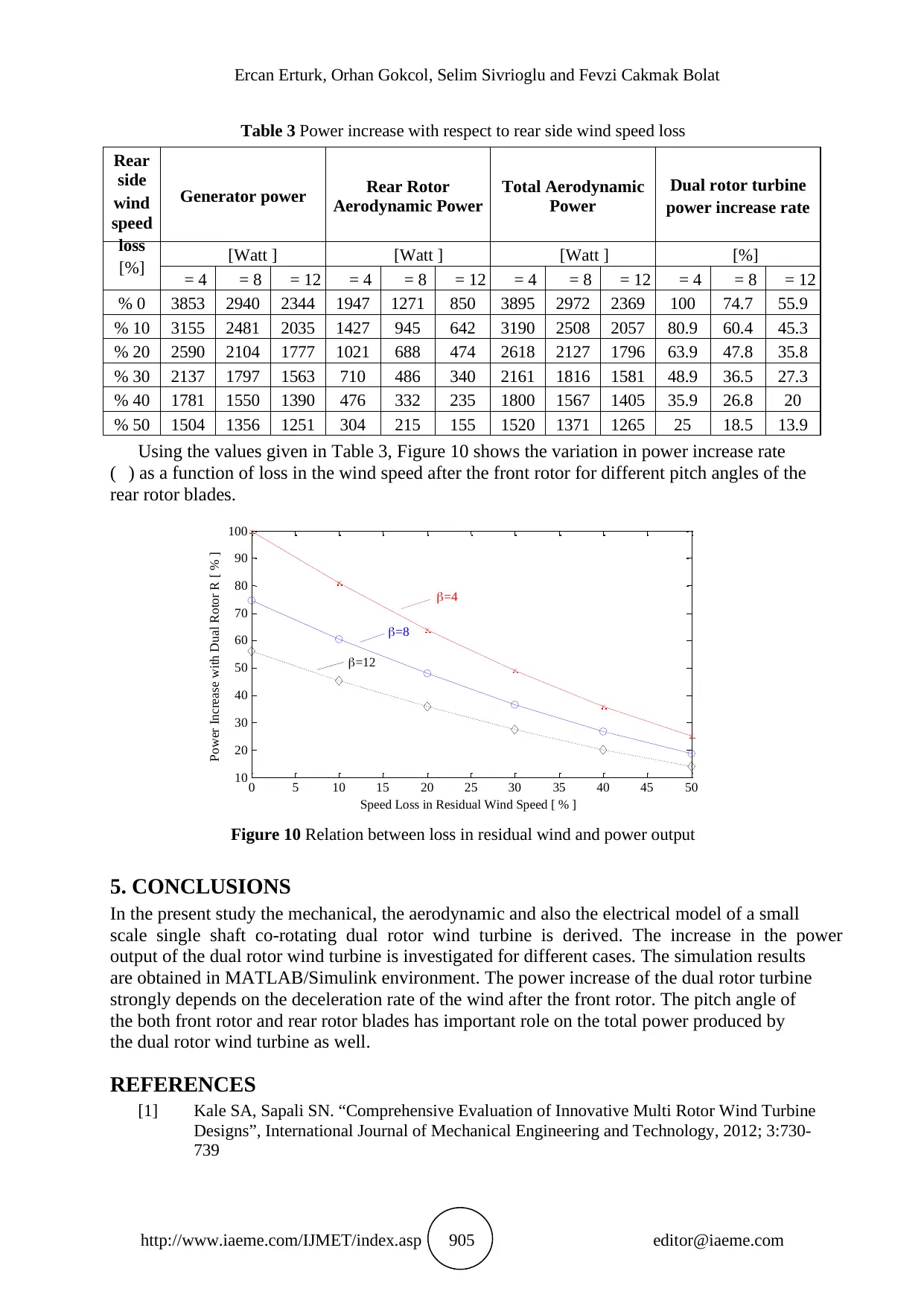
Using the values given in Table 3, Figure 10 shows the variation in power increase rate
( ) as a function of loss in the wind speed after the front rotor for different pitch angles of the
rear rotor blades.
Figure 10 Relation between loss in residual wind and power output
5. CONCLUSIONS
In the present study the mechanical, the aerodynamic and also the electrical model of a small
scale single shaft co-rotating dual rotor wind turbine is derived. The increase in the power
output of the dual rotor wind turbine is investigated for different cases. The simulation results
are obtained in MATLAB/Simulink environment. The power increase of the dual rotor turbine
strongly depends on the deceleration rate of the wind after the front rotor. The pitch angle of
the both front rotor and rear rotor blades has important role on the total power produced by
the dual rotor wind turbine as well.
REFERENCES
[1] Kale SA, Sapali SN. “Comprehensive Evaluation of Innovative Multi Rotor Wind Turbine
Designs”, International Journal of Mechanical Engineering and Technology, 2012; 3:730-
739
0 5 10 15 20 25 30 35 40 45 50
10
20
30
40
50
60
70
80
90
100
Power Increase with Dual Rotor R [ % ]
Speed Loss in Residual Wind Speed [ % ]
=12
=8
=4
http://www.iaeme.com/IJMET/index.asp 905 editor@iaeme.com
Table 3 Power increase with respect to rear side wind speed loss
Rear
side
wind
speed
loss
Generator power Rear Rotor
Aerodynamic Power
Total Aerodynamic
Power
Dual rotor turbine
power increase rate
[%] [Watt ] [Watt ] [Watt ] [%]
= 4 = 8 = 12 = 4 = 8 = 12 = 4 = 8 = 12 = 4 = 8 = 12
% 0 3853 2940 2344 1947 1271 850 3895 2972 2369 100 74.7 55.9
% 10 3155 2481 2035 1427 945 642 3190 2508 2057 80.9 60.4 45.3
% 20 2590 2104 1777 1021 688 474 2618 2127 1796 63.9 47.8 35.8
% 30 2137 1797 1563 710 486 340 2161 1816 1581 48.9 36.5 27.3
% 40 1781 1550 1390 476 332 235 1800 1567 1405 35.9 26.8 20
% 50 1504 1356 1251 304 215 155 1520 1371 1265 25 18.5 13.9
Using the values given in Table 3, Figure 10 shows the variation in power increase rate
( ) as a function of loss in the wind speed after the front rotor for different pitch angles of the
rear rotor blades.
Figure 10 Relation between loss in residual wind and power output
5. CONCLUSIONS
In the present study the mechanical, the aerodynamic and also the electrical model of a small
scale single shaft co-rotating dual rotor wind turbine is derived. The increase in the power
output of the dual rotor wind turbine is investigated for different cases. The simulation results
are obtained in MATLAB/Simulink environment. The power increase of the dual rotor turbine
strongly depends on the deceleration rate of the wind after the front rotor. The pitch angle of
the both front rotor and rear rotor blades has important role on the total power produced by
the dual rotor wind turbine as well.
REFERENCES
[1] Kale SA, Sapali SN. “Comprehensive Evaluation of Innovative Multi Rotor Wind Turbine
Designs”, International Journal of Mechanical Engineering and Technology, 2012; 3:730-
739
0 5 10 15 20 25 30 35 40 45 50
10
20
30
40
50
60
70
80
90
100
Power Increase with Dual Rotor R [ % ]
Speed Loss in Residual Wind Speed [ % ]
=12
=8
=4
⊘ This is a preview!⊘
Do you want full access?
Subscribe today to unlock all pages.
Trusted by 1+ million students worldwide
Modeling and Analysis of a Single Shaft Co-Rotating Dual Rotor Small Wind Turbine
http://www.iaeme.com/IJMET/index.asp 906 editor@iaeme.com
[2] Newman BG. "Actuator-disc theory for vertical-axis wind turbines". Journal of Wind
Engineering and Industrial Aerodynamics, 1983; 15:347-355
[3] Newman BG. "Multiple actuator-disc theory for wind turbines". Journal of Wind
Engineering and Industrial Aerodynamics, 1986; 24:215-225
[4] Shen WZ, Zakkam VAK, Sørensen JN, Appa K. "Analysis of Counter-Rotating Wind
Turbines". Journal of Physics: Conference Series, 2007; 75:012003
[5] Habash RWY, Groza V, Yang Y, Blouin C, Guillemette P. "Performance of a
Contrarotating Small Wind Energy Converter". ISRN Mechanical Engineering, 2011;
Article ID 828739
[6] Mitulet LA, Oprina G, Chihaia RA, Nicolaie S, Nedelcu A, Popescu M. "Wind Tunnel
Testing for a New Experimental Model of Counter-rotating Wind Turbine". Procedia
Engineering, 2015; 100:1141-1149
[7] Jung SN, No TS, Ryu KW. "Aerodynamic performance prediction of a 30 kW counter-
rotating wind turbine system". Renewable Energy, 2005; 30:631-644
[8] Ozbay A, Tian W, Hu H. An Experimental Investigation on the Aeromechanics and Near
Wake Characteristics of Dual-Rotor Wind Turbines (DRWTs). AIAA SciTech Book
Series, 32nd ASME Wind Energy Symposium, AIAA 2014-1085
[9] Muljadi E, Butterfield CP. “Pitch-Controlled Variable-Speed Wind Turbine Generation”.
IEEE Transactions on Industry Applications, 2001; 37:240-246
[10] Baloch MH, Wang J, Kaloi GS. “Dynamic Modeling and Control of Wind Turbine
Scheme Based on Cage Generator for Power System Stability Studies”, International
Journal of Renewable Energy Research, 2016; 6:599-606
[11] Okedu KE. “Hybrid Control Strategy for Variable Speed Wind Turbine Power
Converters”, International Journal of Renewable Energy Research, 2013; 3:283-288
[12] Moazen M, Kazemzadeh R, Azizian MR. “Power Control of BDFRG Variable-Speed
Wind Turbine System Covering All Wind Velocity Ranges”, International Journal of
Renewable Energy Research, 2016; 6:477-486
[13] No TS, Kim JE, Moon JH, Kim SJ. “Modeling, control, and simulation of dual rotor wind
turbine generator system”, Renewable Energy, 2009; 34:2124-2132
[14] Farahani EM, Hosseinzadeh N, Ektesabi MM. “Comparison of Dynamic Responses of
Dual and Single Rotor Wind Turbines under Transient Conditions”, 2010 IEEE
International Conference on Sustainable Energy Technologies (ICSET)
[15] Ozbay U, Zergeroglu E, Sivrioglu S. “Adaptive backstepping control of variable speed
wind turbines”, International Journal of Control, 2008; 6:910-919
[16] Abomahdi MA, Bharadwaj AK. “Modeling and Simulation of DFIG to Grid Connected
Wind Power Generation Using MATLAB”, International Journal of Electrical
Engineering and Technology, 2015; 6:29-40
[17] Alamin AS, Shrivastava J. “Analyzing Fuzzy Control Model for Variable Speed Pitch
Wind System Connected to Grid”, International Journal of Electrical Engineering and
Technology, 2017; 8:01-14
[18] Anas Abdulqader Khalaf AA. “Unified Power Control Under Different Grid Conditions
for PMSG-Based WECS”, International Journal of Electrical Engineering and
Technology, 2014; 5:44-56
[19] Prasad KRL, Sekhar KC. “A New Sensorless Control Strategy for a Variable Speed
PMSG Wind Energy System Connected to Grid”, International Journal of Electrical
Engineering and Technology, 2013; 4:146-154
[20] Iov F, Hansen AD, Sørensen P, Blaabjerg F. “Wind Turbine Blockset in Matlab/Simulink.
General Overview and Description of the Models”, Aalborg University, 2004;
ISBN:8789179463
1 out of 10
Your All-in-One AI-Powered Toolkit for Academic Success.
+13062052269
info@desklib.com
Available 24*7 on WhatsApp / Email
![[object Object]](/_next/static/media/star-bottom.7253800d.svg)
Unlock your academic potential
Copyright © 2020–2026 A2Z Services. All Rights Reserved. Developed and managed by ZUCOL.