Civil Engineering Report: Dynamic Analysis of High-Rise Building, NZ
VerifiedAdded on 2022/11/19
|28
|3371
|71
Report
AI Summary
This report details a dynamic analysis of an 8-story high-rise building, focusing on seismic effects in New Zealand. The project utilizes AS1170.4 standards and SpaceGass software for analysis. The report begins with an introduction, outlining the motivation, proposal, design requirements, and report outline. It includes a literature review, background information on dynamic analysis, and an overview of the SpaceGass software. The analysis involves model development, load case assignments, and simulation results. The report covers manual calculations based on Australian standards, along with the structural response parameters, simulation results, and visualizations. The report concludes with findings and references, providing a comprehensive study on the building's seismic performance and structural integrity.

2019
Dynamic Analysis of the high rise building
Dynamic Analysis of the high rise building
Paraphrase This Document
Need a fresh take? Get an instant paraphrase of this document with our AI Paraphraser
Contents
List of Figures..................................................................................................................................2
Executive Summary.........................................................................................................................3
1 Introduction..............................................................................................................................3
1.1 Motivation.........................................................................................................................3
1.2 Proposal.............................................................................................................................3
1.3 Design Requirements........................................................................................................4
1.4 Outline...............................................................................................................................4
2 Background and Literature Review..........................................................................................4
3 Dynamic analysis on building on seismic effect......................................................................6
4 Dynamic analysis of high rise building....................................................................................7
5 Software overview....................................................................................................................8
6 Experiments and analysis.........................................................................................................9
6.1 Model Development..........................................................................................................9
6.2 Load case assigning........................................................................................................10
6.3 Simulation and Result review.........................................................................................11
7 Conclusions............................................................................................................................14
8 References..............................................................................................................................14
9 Appendix................................................................................................................................16
1
List of Figures
Figure 1-1 Layout of the building................................................................................................................4
Figure 6-1 Model.........................................................................................................................................9
Figure 6-2 AS1170 4.................................................................................................................................10
Figure 6-3 Spectral Loads..........................................................................................................................10
Figure 6-4 Combinational Loads...............................................................................................................11
Figure 6-5 Analysis Case setup.................................................................................................................11
Figure 6-6 Overall Deformation................................................................................................................12
Figure 6-7 Spectral Response of the building............................................................................................13
2
⊘ This is a preview!⊘
Do you want full access?
Subscribe today to unlock all pages.
Trusted by 1+ million students worldwide
Executive Summary
This research report discusses the seismic analysis of the eight-storey building. This
research project starts with the analysis of previous journals related to the seismic analysis. Then
the manual calculations are calculated using the Australian standards. The various structural
response parameters such as storey displacement, storey drift, base shear and storey displacement
and storey stiffness are calculated. For the seismic load calculations New Zealand is considered.
Then the simulations are conducted using SpaceGass software. And the results are visualized in
this report.
1 Introduction
1.1 Motivation
In New Zealand earthquake is the big problem. The country follows strict building norms.
Approximately 10000+ earthquakes are happening in and around the country each year.
Earthquakes cause severe damage to the buildings and constructions (Beiraghi, 2016). Especially
it shows a huge impact on the high rise buildings. These issues motivated me to work on this
project.
1.2 Proposal
This project is intended to carry out the dynamic analysis on high rise building which has 8
stories. The proposed project work aimed to analyze the earthquake and its impact on the
structure. It includes both manual calculations and FEA analysis. The proposed work uses
AS1170 standards. For FEA analysis SpaceGass software will be used (Bhatti, 2016).
3
Paraphrase This Document
Need a fresh take? Get an instant paraphrase of this document with our AI Paraphraser
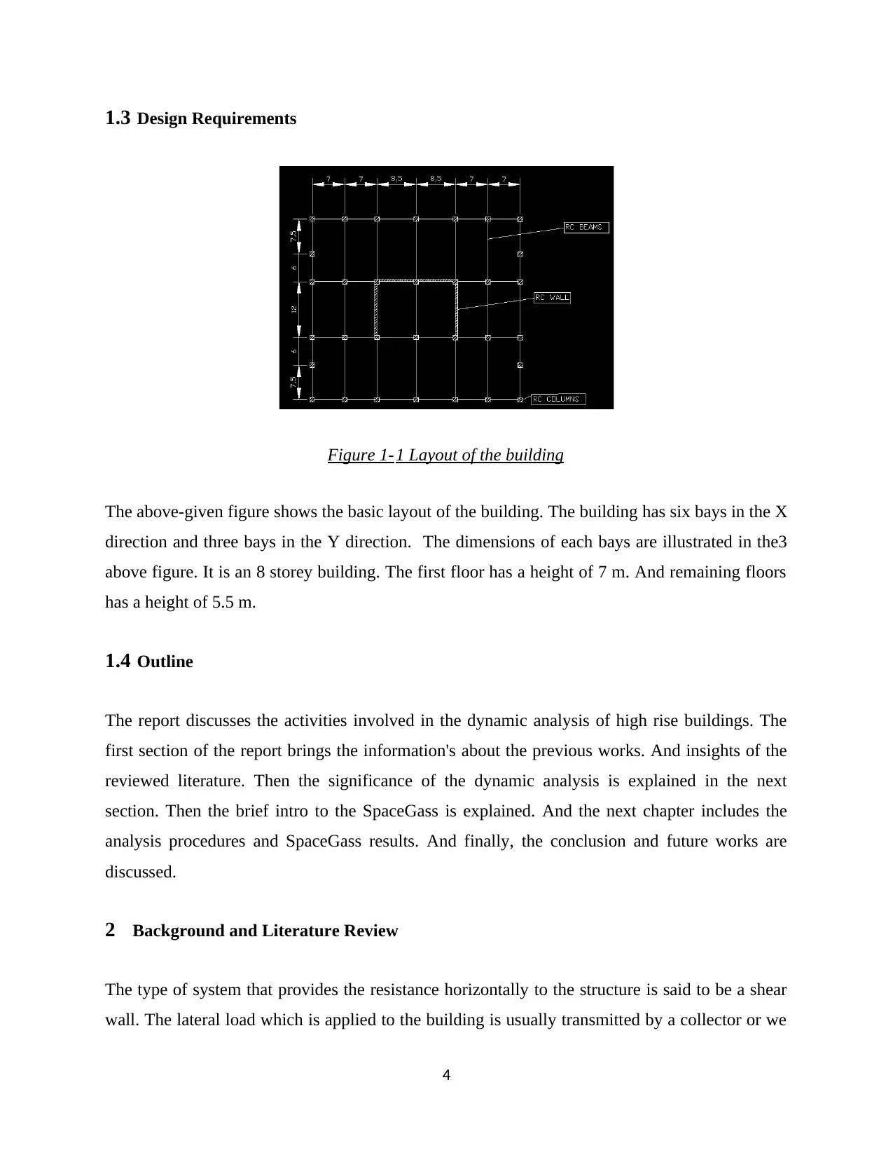
1.3 Design Requirements
Figure 1-1 Layout of the building
The above-given figure shows the basic layout of the building. The building has six bays in the X
direction and three bays in the Y direction. The dimensions of each bays are illustrated in the3
above figure. It is an 8 storey building. The first floor has a height of 7 m. And remaining floors
has a height of 5.5 m.
1.4 Outline
The report discusses the activities involved in the dynamic analysis of high rise buildings. The
first section of the report brings the information's about the previous works. And insights of the
reviewed literature. Then the significance of the dynamic analysis is explained in the next
section. Then the brief intro to the SpaceGass is explained. And the next chapter includes the
analysis procedures and SpaceGass results. And finally, the conclusion and future works are
discussed.
2 Background and Literature Review
The type of system that provides the resistance horizontally to the structure is said to be a shear
wall. The lateral load which is applied to the building is usually transmitted by a collector or we
4
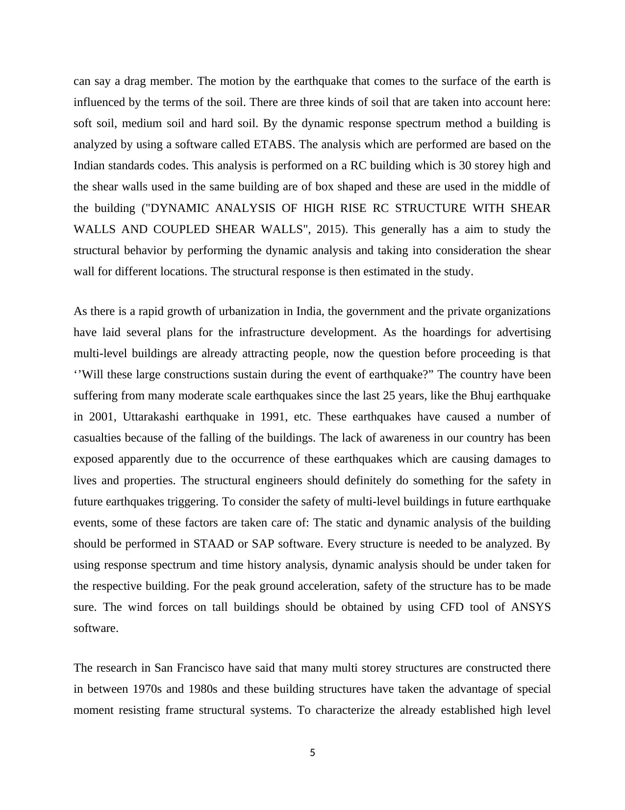
can say a drag member. The motion by the earthquake that comes to the surface of the earth is
influenced by the terms of the soil. There are three kinds of soil that are taken into account here:
soft soil, medium soil and hard soil. By the dynamic response spectrum method a building is
analyzed by using a software called ETABS. The analysis which are performed are based on the
Indian standards codes. This analysis is performed on a RC building which is 30 storey high and
the shear walls used in the same building are of box shaped and these are used in the middle of
the building ("DYNAMIC ANALYSIS OF HIGH RISE RC STRUCTURE WITH SHEAR
WALLS AND COUPLED SHEAR WALLS", 2015). This generally has a aim to study the
structural behavior by performing the dynamic analysis and taking into consideration the shear
wall for different locations. The structural response is then estimated in the study.
As there is a rapid growth of urbanization in India, the government and the private organizations
have laid several plans for the infrastructure development. As the hoardings for advertising
multi-level buildings are already attracting people, now the question before proceeding is that
‘’Will these large constructions sustain during the event of earthquake?” The country have been
suffering from many moderate scale earthquakes since the last 25 years, like the Bhuj earthquake
in 2001, Uttarakashi earthquake in 1991, etc. These earthquakes have caused a number of
casualties because of the falling of the buildings. The lack of awareness in our country has been
exposed apparently due to the occurrence of these earthquakes which are causing damages to
lives and properties. The structural engineers should definitely do something for the safety in
future earthquakes triggering. To consider the safety of multi-level buildings in future earthquake
events, some of these factors are taken care of: The static and dynamic analysis of the building
should be performed in STAAD or SAP software. Every structure is needed to be analyzed. By
using response spectrum and time history analysis, dynamic analysis should be under taken for
the respective building. For the peak ground acceleration, safety of the structure has to be made
sure. The wind forces on tall buildings should be obtained by using CFD tool of ANSYS
software.
The research in San Francisco have said that many multi storey structures are constructed there
in between 1970s and 1980s and these building structures have taken the advantage of special
moment resisting frame structural systems. To characterize the already established high level
5
⊘ This is a preview!⊘
Do you want full access?
Subscribe today to unlock all pages.
Trusted by 1+ million students worldwide
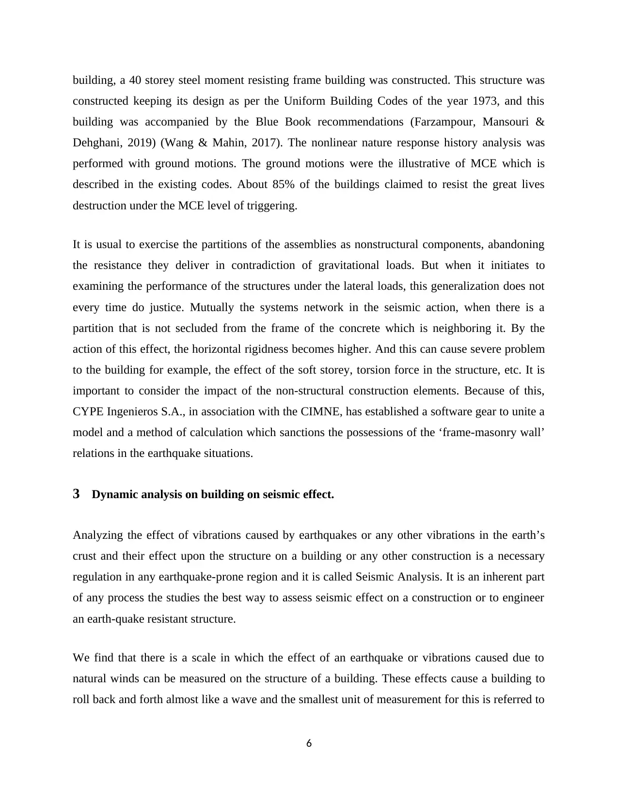
building, a 40 storey steel moment resisting frame building was constructed. This structure was
constructed keeping its design as per the Uniform Building Codes of the year 1973, and this
building was accompanied by the Blue Book recommendations (Farzampour, Mansouri &
Dehghani, 2019) (Wang & Mahin, 2017). The nonlinear nature response history analysis was
performed with ground motions. The ground motions were the illustrative of MCE which is
described in the existing codes. About 85% of the buildings claimed to resist the great lives
destruction under the MCE level of triggering.
It is usual to exercise the partitions of the assemblies as nonstructural components, abandoning
the resistance they deliver in contradiction of gravitational loads. But when it initiates to
examining the performance of the structures under the lateral loads, this generalization does not
every time do justice. Mutually the systems network in the seismic action, when there is a
partition that is not secluded from the frame of the concrete which is neighboring it. By the
action of this effect, the horizontal rigidness becomes higher. And this can cause severe problem
to the building for example, the effect of the soft storey, torsion force in the structure, etc. It is
important to consider the impact of the non-structural construction elements. Because of this,
CYPE Ingenieros S.A., in association with the CIMNE, has established a software gear to unite a
model and a method of calculation which sanctions the possessions of the ‘frame-masonry wall’
relations in the earthquake situations.
3 Dynamic analysis on building on seismic effect.
Analyzing the effect of vibrations caused by earthquakes or any other vibrations in the earth’s
crust and their effect upon the structure on a building or any other construction is a necessary
regulation in any earthquake-prone region and it is called Seismic Analysis. It is an inherent part
of any process the studies the best way to assess seismic effect on a construction or to engineer
an earth-quake resistant structure.
We find that there is a scale in which the effect of an earthquake or vibrations caused due to
natural winds can be measured on the structure of a building. These effects cause a building to
roll back and forth almost like a wave and the smallest unit of measurement for this is referred to
6
Paraphrase This Document
Need a fresh take? Get an instant paraphrase of this document with our AI Paraphraser
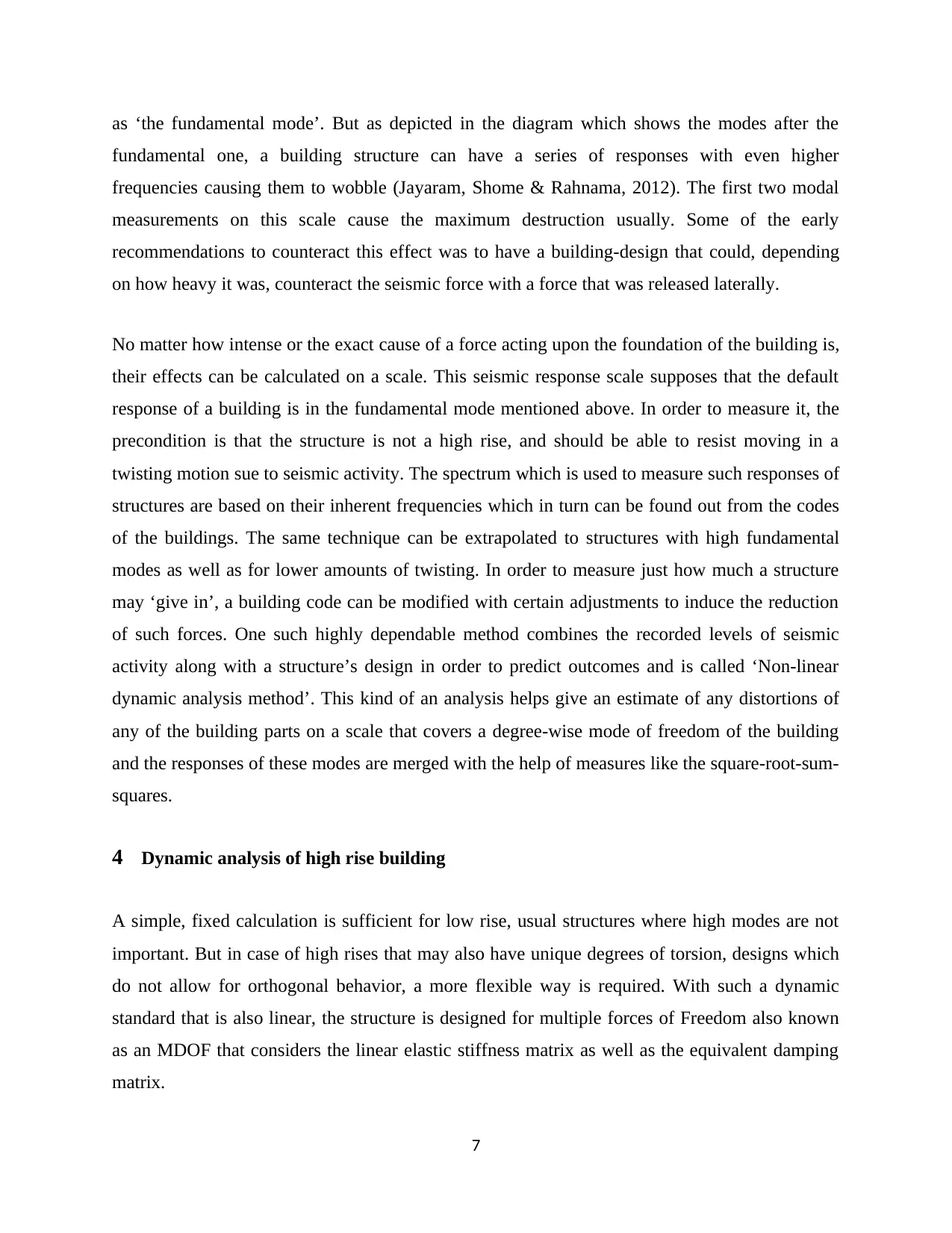
as ‘the fundamental mode’. But as depicted in the diagram which shows the modes after the
fundamental one, a building structure can have a series of responses with even higher
frequencies causing them to wobble (Jayaram, Shome & Rahnama, 2012). The first two modal
measurements on this scale cause the maximum destruction usually. Some of the early
recommendations to counteract this effect was to have a building-design that could, depending
on how heavy it was, counteract the seismic force with a force that was released laterally.
No matter how intense or the exact cause of a force acting upon the foundation of the building is,
their effects can be calculated on a scale. This seismic response scale supposes that the default
response of a building is in the fundamental mode mentioned above. In order to measure it, the
precondition is that the structure is not a high rise, and should be able to resist moving in a
twisting motion sue to seismic activity. The spectrum which is used to measure such responses of
structures are based on their inherent frequencies which in turn can be found out from the codes
of the buildings. The same technique can be extrapolated to structures with high fundamental
modes as well as for lower amounts of twisting. In order to measure just how much a structure
may ‘give in’, a building code can be modified with certain adjustments to induce the reduction
of such forces. One such highly dependable method combines the recorded levels of seismic
activity along with a structure’s design in order to predict outcomes and is called ‘Non-linear
dynamic analysis method’. This kind of an analysis helps give an estimate of any distortions of
any of the building parts on a scale that covers a degree-wise mode of freedom of the building
and the responses of these modes are merged with the help of measures like the square-root-sum-
squares.
4 Dynamic analysis of high rise building
A simple, fixed calculation is sufficient for low rise, usual structures where high modes are not
important. But in case of high rises that may also have unique degrees of torsion, designs which
do not allow for orthogonal behavior, a more flexible way is required. With such a dynamic
standard that is also linear, the structure is designed for multiple forces of Freedom also known
as an MDOF that considers the linear elastic stiffness matrix as well as the equivalent damping
matrix.
7
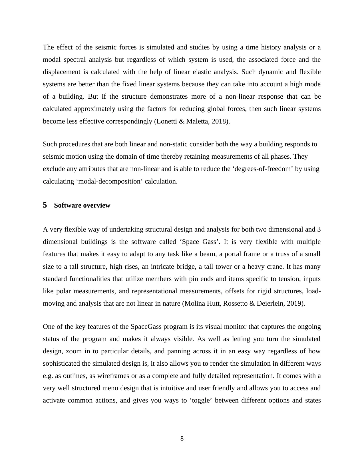
The effect of the seismic forces is simulated and studies by using a time history analysis or a
modal spectral analysis but regardless of which system is used, the associated force and the
displacement is calculated with the help of linear elastic analysis. Such dynamic and flexible
systems are better than the fixed linear systems because they can take into account a high mode
of a building. But if the structure demonstrates more of a non-linear response that can be
calculated approximately using the factors for reducing global forces, then such linear systems
become less effective correspondingly (Lonetti & Maletta, 2018).
Such procedures that are both linear and non-static consider both the way a building responds to
seismic motion using the domain of time thereby retaining measurements of all phases. They
exclude any attributes that are non-linear and is able to reduce the ‘degrees-of-freedom’ by using
calculating ‘modal-decomposition’ calculation.
5 Software overview
A very flexible way of undertaking structural design and analysis for both two dimensional and 3
dimensional buildings is the software called ‘Space Gass’. It is very flexible with multiple
features that makes it easy to adapt to any task like a beam, a portal frame or a truss of a small
size to a tall structure, high-rises, an intricate bridge, a tall tower or a heavy crane. It has many
standard functionalities that utilize members with pin ends and items specific to tension, inputs
like polar measurements, and representational measurements, offsets for rigid structures, load-
moving and analysis that are not linear in nature (Molina Hutt, Rossetto & Deierlein, 2019).
One of the key features of the SpaceGass program is its visual monitor that captures the ongoing
status of the program and makes it always visible. As well as letting you turn the simulated
design, zoom in to particular details, and panning across it in an easy way regardless of how
sophisticated the simulated design is, it also allows you to render the simulation in different ways
e.g. as outlines, as wireframes or as a complete and fully detailed representation. It comes with a
very well structured menu design that is intuitive and user friendly and allows you to access and
activate common actions, and gives you ways to ‘toggle’ between different options and states
8
⊘ This is a preview!⊘
Do you want full access?
Subscribe today to unlock all pages.
Trusted by 1+ million students worldwide
easily with very visual navigation aids. It also provides help and user support by making the
entire user-manual available screen-wise in a contextual way.
It also allows the user to choose between a visual way of entering information as well as a textual
input that allows all data formats called the ‘Datasheet Input. It allows for unique data outputs
and manipulation but also allows unique ways of entering data like ‘section property shape’ or
‘material library’. It also allows the user to feed in a standardized structural wizard, as well as a
way to feed in text in a ‘pro forma’ format.
6 Experiments and analysis
The experimental analysis consist three stages. And they are listed below.
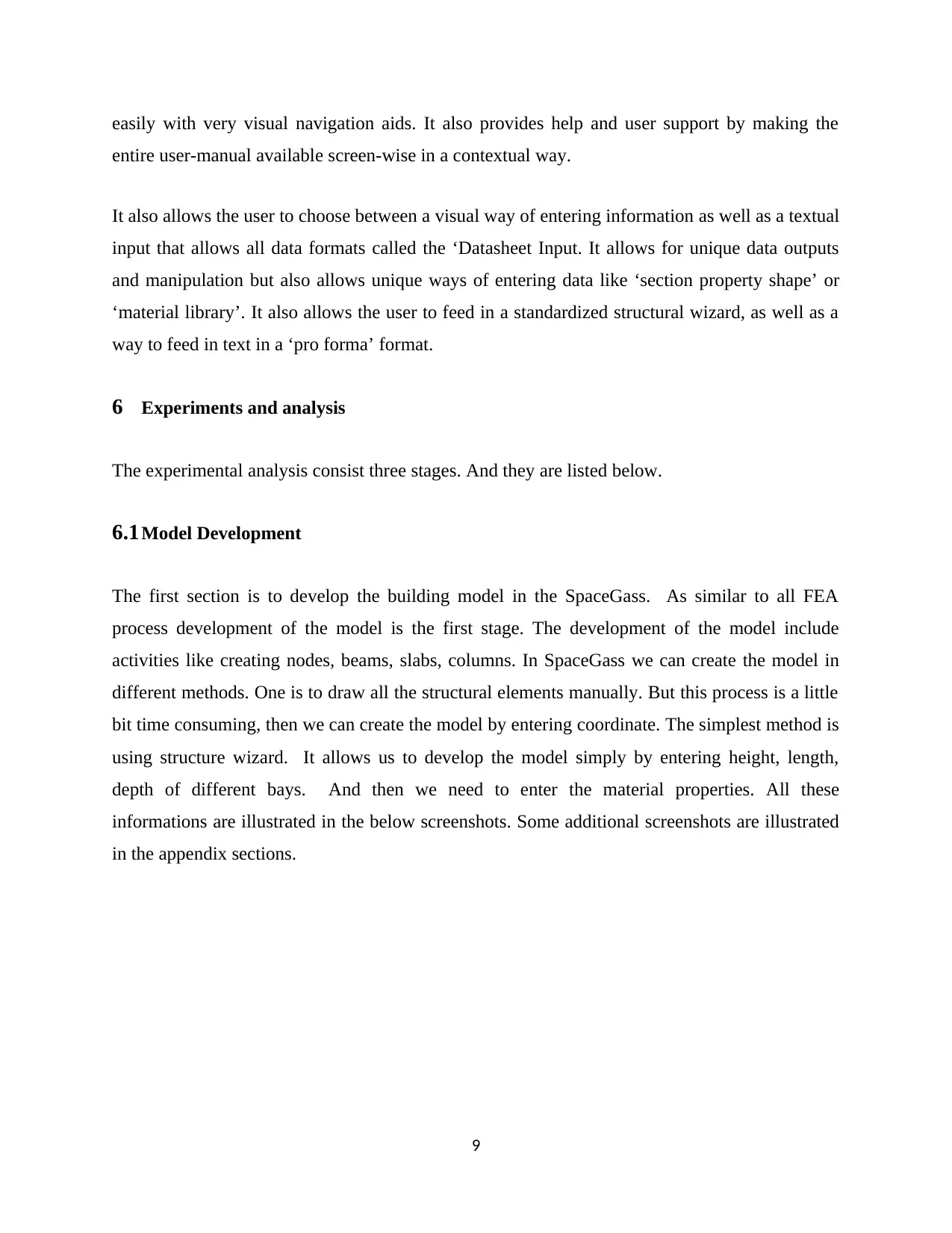
6.1Model Development
The first section is to develop the building model in the SpaceGass. As similar to all FEA
process development of the model is the first stage. The development of the model include
activities like creating nodes, beams, slabs, columns. In SpaceGass we can create the model in
different methods. One is to draw all the structural elements manually. But this process is a little
bit time consuming, then we can create the model by entering coordinate. The simplest method is
using structure wizard. It allows us to develop the model simply by entering height, length,
depth of different bays. And then we need to enter the material properties. All these
informations are illustrated in the below screenshots. Some additional screenshots are illustrated
in the appendix sections.
9
entire user-manual available screen-wise in a contextual way.
It also allows the user to choose between a visual way of entering information as well as a textual
input that allows all data formats called the ‘Datasheet Input. It allows for unique data outputs
and manipulation but also allows unique ways of entering data like ‘section property shape’ or
‘material library’. It also allows the user to feed in a standardized structural wizard, as well as a
way to feed in text in a ‘pro forma’ format.
6 Experiments and analysis
The experimental analysis consist three stages. And they are listed below.
6.1Model Development
The first section is to develop the building model in the SpaceGass. As similar to all FEA
process development of the model is the first stage. The development of the model include
activities like creating nodes, beams, slabs, columns. In SpaceGass we can create the model in
different methods. One is to draw all the structural elements manually. But this process is a little
bit time consuming, then we can create the model by entering coordinate. The simplest method is
using structure wizard. It allows us to develop the model simply by entering height, length,
depth of different bays. And then we need to enter the material properties. All these
informations are illustrated in the below screenshots. Some additional screenshots are illustrated
in the appendix sections.
9
Paraphrase This Document
Need a fresh take? Get an instant paraphrase of this document with our AI Paraphraser
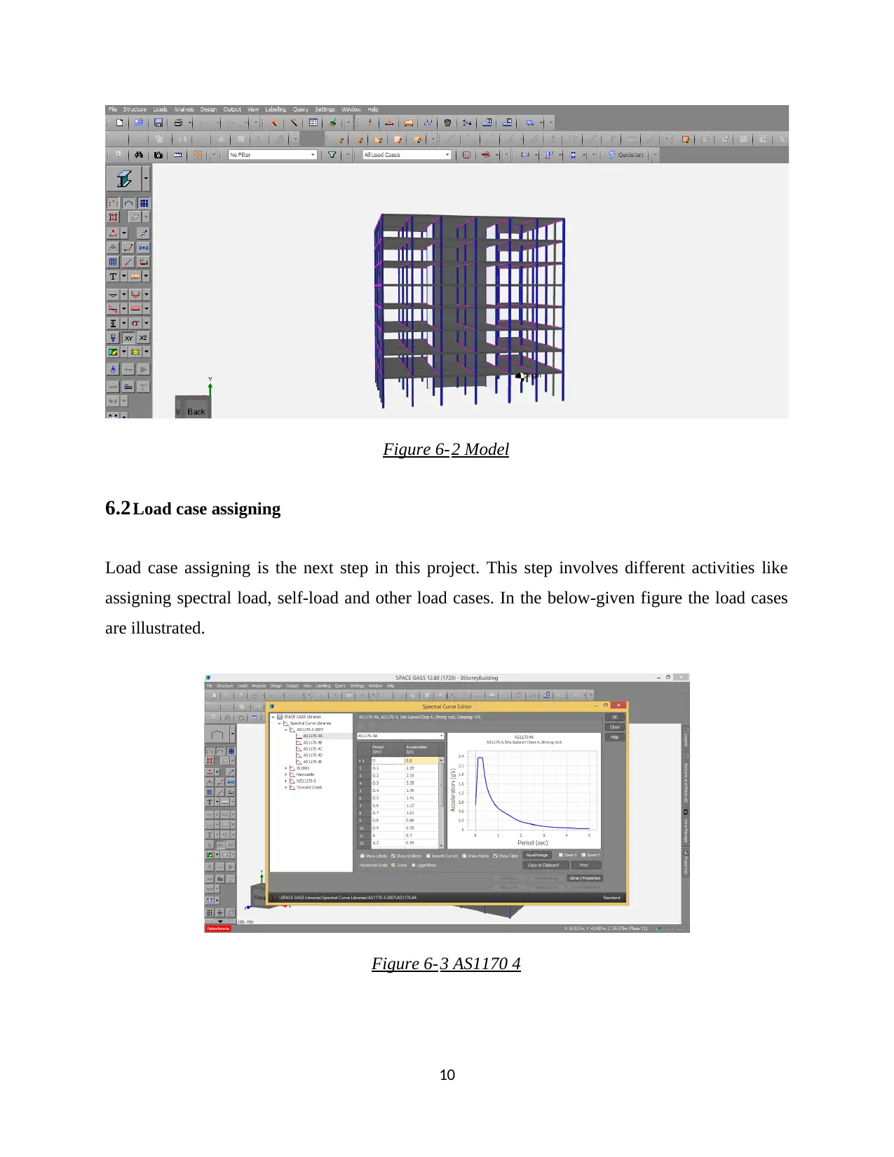
Figure 6-2 Model
6.2Load case assigning
Load case assigning is the next step in this project. This step involves different activities like
assigning spectral load, self-load and other load cases. In the below-given figure the load cases
are illustrated.
Figure 6-3 AS1170 4
10
6.2Load case assigning
Load case assigning is the next step in this project. This step involves different activities like
assigning spectral load, self-load and other load cases. In the below-given figure the load cases
are illustrated.
Figure 6-3 AS1170 4
10
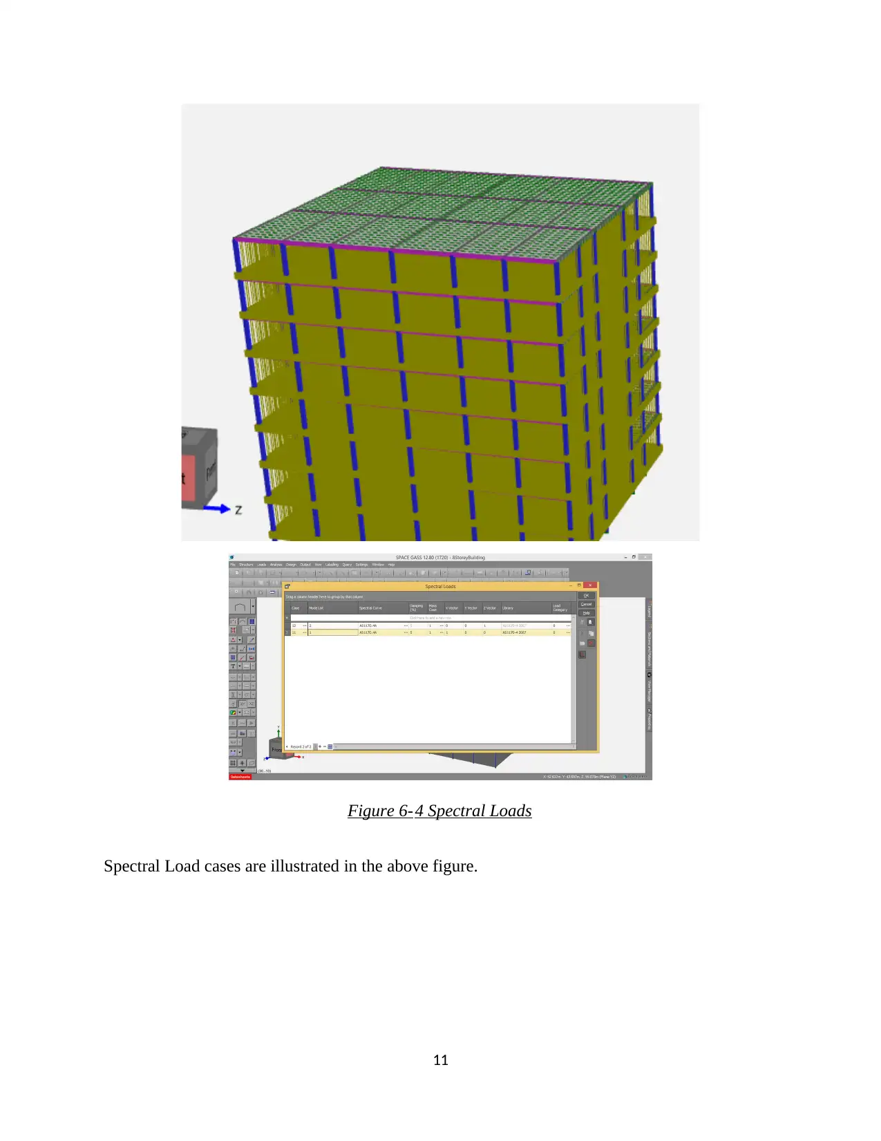
Figure 6-4 Spectral Loads
Spectral Load cases are illustrated in the above figure.
11
Spectral Load cases are illustrated in the above figure.
11
⊘ This is a preview!⊘
Do you want full access?
Subscribe today to unlock all pages.
Trusted by 1+ million students worldwide
1 out of 28


Your All-in-One AI-Powered Toolkit for Academic Success.
+13062052269
info@desklib.com
Available 24*7 on WhatsApp / Email
![[object Object]](/_next/static/media/star-bottom.7253800d.svg)
Unlock your academic potential
Copyright © 2020–2025 A2Z Services. All Rights Reserved. Developed and managed by ZUCOL.