Engineering Science Report on Dynamic Engineering Systems

Verified

Added on  2023/04/22

|11
|1011
|296
Report
AI Summary
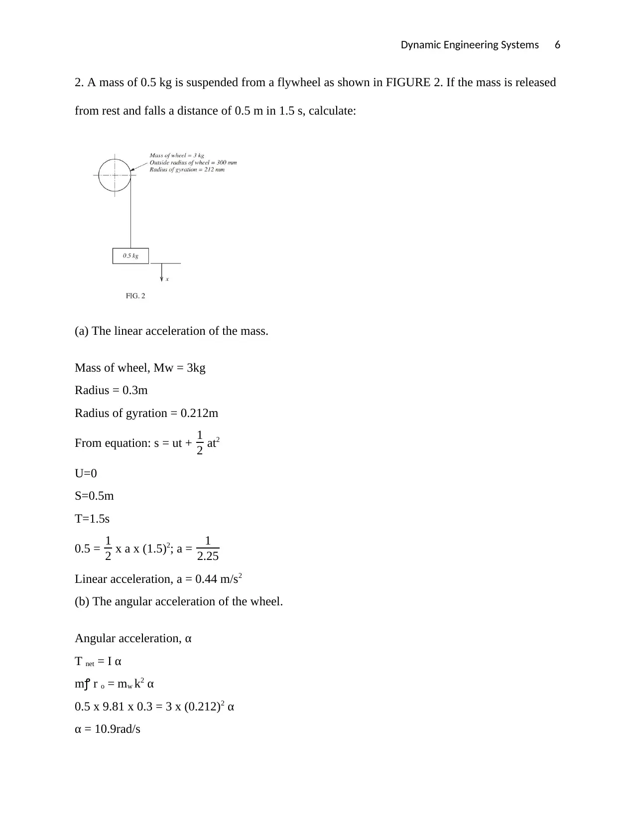
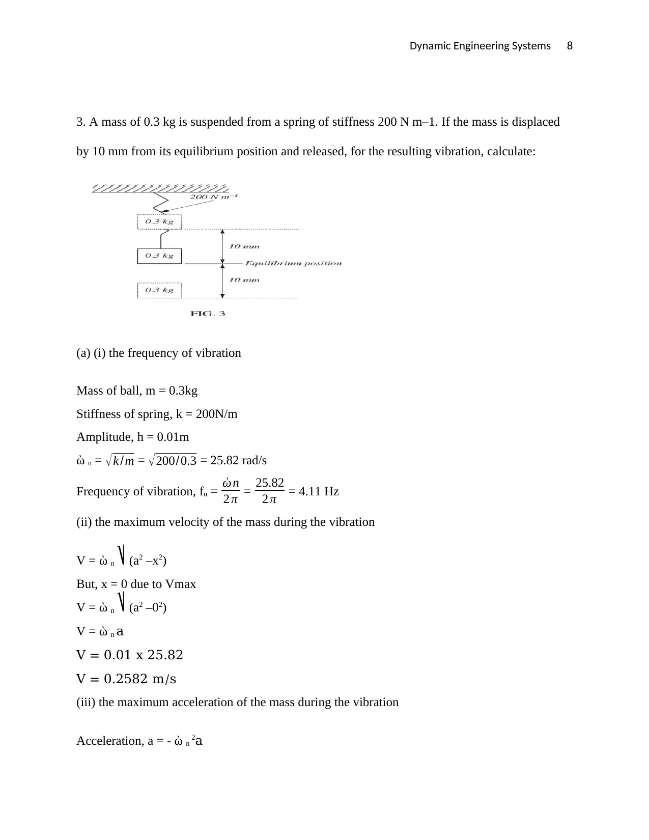
This report provides a detailed analysis of dynamic engineering systems, starting with calculating the total energy expended in accelerating a mass subjected to a horizontal force, including plotting graphs of kinetic energy against time and distance, and determining the coefficient of friction. It proceeds to analyze a mass suspended from a flywheel, calculating linear and angular acceleration, tension in the rope, and frictional torque. Finally, the report investigates a mass suspended from a spring, determining the frequency of vibration, maximum velocity and acceleration, and the mass required to double the maximum velocity, concluding with a graph of acceleration against displacement. This report provides valuable insights and calculations related to dynamic engineering principles.
Document Page
Dynamic Engineering Systems 1
DYNAMIC ENGINEERING SYSTEMS
A Research Paper on Engineering Science By
Student’s Name
Name of the Professor
Institutional Affiliation
City/State
Year/Month/Day
tabler-icon-diamond-filled.svg

Paraphrase This Document

Need a fresh take? Get an instant paraphrase of this document with our AI Paraphraser
Document Page
Dynamic Engineering Systems 2
A horizontal force of 80 N acts on a mass of 6 kg resting on a horizontal surface. The mass is
initially at rest and covers a distance of 5 m in 0.92 s under the action of the force. Assuming
there are no energy losses due to air resistance and therefore that the acceleration is constant:
(a) Calculate the total energy expended in the acceleration.
Force applied, F = 80N
Mass of box, m = 6kg
Distance covered, d = 5m
Time, t = 0.92s
Initial velocity of the box, u = 0m/s
Total energy expenditure = Work done x Distance
E = F x d
E = 80 x 5
= 400J
(b) Plot a graph of the kinetic energy of the mass against time.
Since acceleration, a = am/s2
Equation of motion; d = ut + 1
2 at2
Will be reduced to: 5 = 0 + 1
2 a (0.92)2
Therefore, a = 11.81m/s2
Velocity, v = u + at
Document Page
Dynamic Engineering Systems 3
V = 0 + (11.81)t
= 11.81t
Therefore, KE of box = 1
2 MV2
= 1
2x 6 x (11.81t)2
= 418.43t2
The values of KE and t can be:
Time KE
0 0
0.2 19.73
0.4 66.94
0.6 150.63
0.8 267.79
0.92
(c) Plot a graph of the kinetic energy of the mass against distance.
Document Page
Dynamic Engineering Systems 4
Let s be distance covered after time t
V2 – U2 = 2as
V2 – (0)2 = 2 x 11.81 x s
V2 = 23.62S
KE = 1
2MV2
= 1
2 x 6 x 23.62 x S
= 70.86s
Table of KE and s
Distances (s) KE
0 0
1 70.86
2 141.72
3 212.58
4 283.44
5 354.3
(d) Calculate the coefficient of friction between the mass and the surface.
tabler-icon-diamond-filled.svg

Paraphrase This Document

Need a fresh take? Get an instant paraphrase of this document with our AI Paraphraser
Document Page
Dynamic Engineering Systems 5
Net Force, FN = ma
= 6 x 11.81
= 70.86N
Frictional force = F – FN
= 80 – 70.86
= 9.14N
Normal Reaction, R = mg = 6 x 9.81
R = 58.8N
Coefficient of friction, μ;
F = μR
μ = F/R = 9.14/58.8 = 0.155
Document Page
Dynamic Engineering Systems 6
2. A mass of 0.5 kg is suspended from a flywheel as shown in FIGURE 2. If the mass is released
from rest and falls a distance of 0.5 m in 1.5 s, calculate:
(a) The linear acceleration of the mass.
Mass of wheel, Mw = 3kg
Radius = 0.3m
Radius of gyration = 0.212m
From equation: s = ut + 1
2 at2
U=0
S=0.5m
T=1.5s
0.5 = 1
2 x a x (1.5)2; a = 1
2.25
Linear acceleration, a = 0.44 m/s2
(b) The angular acceleration of the wheel.
Angular acceleration, α
T net = I α
m r o = mw k2 α
0.5 x 9.81 x 0.3 = 3 x (0.212)2 α
α = 10.9rad/s
Document Page
Dynamic Engineering Systems 7
(c) The tension in the rope.
F net = ma
Mg – T = ma
0.5 x 9.81 – T = 0.5 x 0.44
T = 4.68 N
(d) The frictional torque, resisting motion.
T = mgro
T = 0.5 x 9.81 x 0.3
= 1.47N
tabler-icon-diamond-filled.svg

Paraphrase This Document

Need a fresh take? Get an instant paraphrase of this document with our AI Paraphraser
Document Page
Dynamic Engineering Systems 8
3. A mass of 0.3 kg is suspended from a spring of stiffness 200 N m–1. If the mass is displaced
by 10 mm from its equilibrium position and released, for the resulting vibration, calculate:
(a) (i) the frequency of vibration
Mass of ball, m = 0.3kg
Stiffness of spring, k = 200N/m
Amplitude, h = 0.01m
n = k /m = 200/0.3 = 25.82 rad/s
Frequency of vibration, fn = n
2 π = 25.82
2 π = 4.11 Hz
(ii) the maximum velocity of the mass during the vibration
V = ὼ n (a2 –x2)
But, x = 0 due to Vmax
V = ὼ n (a2 –02)
V = ὼ n a
V = 0.01 x 25.82
V = 0.2582 m/s
(iii) the maximum acceleration of the mass during the vibration
Acceleration, a = - ὼ n 2a
Document Page
Dynamic Engineering Systems 9
When a max, x=a
amax = 2a
a = 25.82 x 0.01
a = 6.67 m/s2
(iv) the mass required to produce double the maximum velocity calculated in (ii) using the same
spring and initial deflection.
V = 2 x Vmax
V = 2 x 0.2582
V = 0.5164
V = a ὼ = a k
m
M = ka 2
V 2 = 200 x 0.012/0.51642
M = 0.07499kg
(b) Plot a graph of acceleration against displacement (x) (for values of x
from x = –10 mm to x = +10 mm)
For x = 10, a = -6.67m/s2
Fox x = -10, a = 6.67m/s2
Document Page
Dynamic Engineering Systems 10
tabler-icon-diamond-filled.svg

Paraphrase This Document

Need a fresh take? Get an instant paraphrase of this document with our AI Paraphraser
Document Page
Dynamic Engineering Systems 11
BIBLIOGRAPHY
Brown, F., 2010. Engineering System Dynamics: A Unified Graph-Centered Approach, Second Edition.
Toledo: CRC Press.
Leonides, C., 2012. Control and Dynamic Systems V57: Multidisciplinary Engineering Systems: Design and
Optimization Techniques and Their Application: Advances in Theory and Applications. London: Academic
Press.
Woods, R. & Lawrence, K., 2011. Modeling and simulation of dynamic systems. New York: Prentice Hall.
chevron_up_icon
1 out of 11
circle_padding
hide_on_mobile
zoom_out_icon
[object Object]