Monash University ELEC3160: Dynamic Simulation of Off-Grid Systems
VerifiedAdded on  2023/06/03
|13
|1752
|260
Report
AI Summary
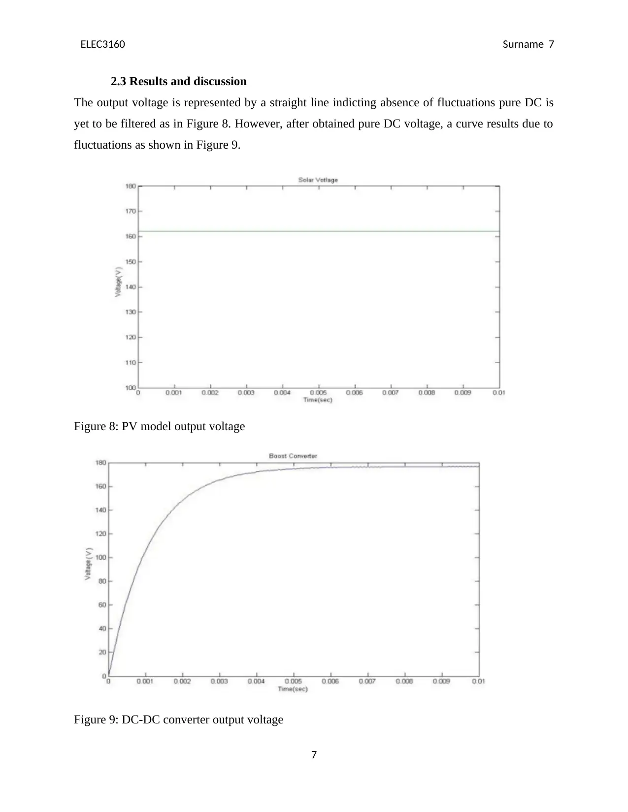
This report presents a comprehensive modeling and simulation of an off-grid Photovoltaic (PV) power system utilizing MATLAB Simulink in conjunction with the Sim Power toolbox. The simulated off-grid system comprises photovoltaic panels, a storage battery, an inverter, electronic components like transformers, diodes, and fuses, and various loads including inductors, capacitors, and resistors. The simulation assesses the stability of all system components under both static and dynamic conditions, ensuring operation within desired frequency and voltage limits. The results of the simulation verified the effectiveness of the control system and the model components, highlighting the importance of component parameters in determining outputs and inverter efficiency. The report recommends the design of off-grid power systems for various applications based on the simulation results.
Contribute Materials
Your contribution can guide someone’s learning journey. Share your
documents today.

ELEC3160 Surname i
Monash University
Faculty of Engineering
ELEC3160 Principles and Design of Off Grid Power Systems
Assignment 3: Dynamic Simulation of the System
Student’s Name:
Registration Number:
Date:
i
Monash University
Faculty of Engineering
ELEC3160 Principles and Design of Off Grid Power Systems
Assignment 3: Dynamic Simulation of the System
Student’s Name:
Registration Number:
Date:
i
Secure Best Marks with AI Grader
Need help grading? Try our AI Grader for instant feedback on your assignments.

ELEC3160 Surname ii
Summary
The report presents modelling and simulation of the off-grid Photovoltaic (PV) power system
using MATLAB Simulink Interface in conjunction with Sim Power toolbox. The off-grid system
comprises of photovoltaic panels, storage battery, inverter, other electronic components like
transformers, diodes and fuses, and various loads including inductors, capacitors and resistors.
All the system components are simulated both in static state and under dynamic conditions to
determine their stability when operating within the desired frequency and voltage limits.
The results verified the effectiveness of the control system and the model components. Since the
entire simulation largely considered the components’ parameters that determined the outputs and
inverter efficiency, we recommend design of off-grid power stems for different applications.
Table of Contents
ii

ELEC3160 Surname iii
Summary..........................................................................................................................................ii
1.0 Introduction...........................................................................................................................1
2.0 Methodology.........................................................................................................................2
2.1 Procedure...............................................................................................................................2
2.2 Design and modelling of off-grid system..............................................................................2
2.2.1 Solar photovoltaic (PV) model........................................................................................3
2.2.2 Inverter model.................................................................................................................6
2.3 Results and discussion...........................................................................................................7
3.0 Conclusion and recommendations........................................................................................8
4.0 References.............................................................................................................................9
iii

ELEC3160 Surname iv
iv
iv
Secure Best Marks with AI Grader
Need help grading? Try our AI Grader for instant feedback on your assignments.

ELEC3160 Surname 1
1.0 Introduction
The increase in global warming due to emission of greenhouse gases has compelled researchers
and industrialists globally to develop alternative sustainable energy systems. Also considering
the consistent increase in the prices of grid electric power, most of electricity users have resolved
for off-grid power systems like photovoltaic power supply [3]. PV is a renewable power source
and hence is a key in sustainable future development. Currently, it is possible to integrate energy
storage systems with renewable energy sources which ensures constant power supply [6]. Off-
grid power systems provide power supply especially in cases of power interruptions and
emergency.
Photovoltaic power systems designed today are capable of generating maximum power to the
grid. The design takes into consideration the power, voltage and frequency fluctuations in the
grid. However, their efficiency relies on the weather condition which is their greatest
disadvantage. Thus, the energy storage system is necessary in ensuring reliable and stable power
supply from the photovoltaic system. It also improves the dynamic and static behaviors of the
whole off-grid power generation system [8].
In this report, a design of off-grid power generation system is presented. The systems consist of
PV panel, loads, power electronic converters, and utility grid. The aim of the project is to model
the system components and use the components to model the whole power generation system.
The PV is connected to the main grid through a converter and inverter which converters the DC
solar voltage output into AC voltage. The battery on the other hand is connected to the DC bus to
stabilize PV voltage. The proposed system models are simulated using the MATLAB Simulink
interface to determine if it meets the requirements both in steady state and under dynamic
conditions. The results verified the effectiveness of the control system and the model
components.
1

ELEC3160 Surname 2
Figure 1: Block diagram of the PV off-grid power system
2.0 Methodology
2.1 Procedure
Energy sources that could be converted into electrical energy were determined. Also, model
loads were identified. Each of the system’s components were modelled after which they were
used to model the whole system. Using MATLAB Simulink environment, the system was
simulated under steady state and dynamic conditions to determine the worst condition effects of
the introduced induction machine. Also, it was determined if the system model met the
requirements both in steady state and under dynamic conditions.
2.2 Design and modelling of off-grid system
The Simulink model of the whole PV off-grid power generation system is shown in figure 2.
2

ELEC3160 Surname 3
Figure 2: Simulink model of the whole PV off-grid power generation system
2.2.1 Solar photovoltaic (PV) model
Figure 3 shows the theoretical equivalent circuit for the PV system model. It consists of two
resistors and one current source. The P-N transition and the current source of the solar represents
the photocurrent generated when the solar cell is exposed to light [1]. However, energy losses
experienced in the solar cell are represented by the series and shunt resistances given in the
equivalent circuit [2].
Figure 4,5 and 6 represents the equivalent circuit model in MATLAB Simulink for various PV
model characteristics. Just like in the case of theoretical circuit, it also has one current source.
Mathematical functions are used to develop the input parameters and thus any information
regarding the PV model can be determined from mathematical calculations [4]. This includes the
model currents that is, Ip, diode saturation current (Io), and Ipv. The system is modelled based on
the following mathematical equations [5]. Equation 1 represents the current-voltage
characteristics of the PV system model.
3
Paraphrase This Document
Need a fresh take? Get an instant paraphrase of this document with our AI Paraphraser

ELEC3160 Surname 4
(1)
(2)
(3)
(4)
(5)
Figure 3: Equivalent circuit for the PV system model
4
(1)
(2)
(3)
(4)
(5)
Figure 3: Equivalent circuit for the PV system model
4

ELEC3160 Surname 5
Figure 4: Simulink model for PV saturation current (Io) equation
Figure 5: Simulink model for PV Ipv equation
Figure 6: Simulink model for PV Im=Ipv -Idd equation
5
Figure 4: Simulink model for PV saturation current (Io) equation
Figure 5: Simulink model for PV Ipv equation
Figure 6: Simulink model for PV Im=Ipv -Idd equation
5

ELEC3160 Surname 6
2.2.2 Inverter model
In this project, a single phase inverter is designed and modelled to convert the DC output of the
PV solar to AC voltage which can be connected to the utility grid. It comprises of power
switching blocks, DC input voltage source and decoupling capacitor at the input used for noise
filtering. Most significant parameters including input and output voltages and the values of
resistors, capacitors and inductors were considered [7]. Therefore, Simulink modelling of the
single phase inverter also included that of the DC-DC converter. DC-DC converter is also known
as the boost converter. The output voltage in a DC-DC converter is given by equation 6 [2].
Pulse width modulation (PWM) is used to effectively control the frequency and output amplitude
voltage [6].
(6)
Figure 7: Simulink model of single phase inverter and DC-DC converter
6
Secure Best Marks with AI Grader
Need help grading? Try our AI Grader for instant feedback on your assignments.

ELEC3160 Surname 7
2.3 Results and discussion
The output voltage is represented by a straight line indicting absence of fluctuations pure DC is
yet to be filtered as in Figure 8. However, after obtained pure DC voltage, a curve results due to
fluctuations as shown in Figure 9.
Figure 8: PV model output voltage
Figure 9: DC-DC converter output voltage
7

ELEC3160 Surname 8
The inverter output voltage shown in figure 10 indicates that it can be used also to supply an
external DC load since it is connected to the battery directly.
Figure 10: The output of the inverter Simulink model
3.0 Conclusion and recommendations
In this project, the dynamic behaviors of the PV off-grid power generation system were
implemented in MATLAB Simulink environment. Various system control methods are also
proposed including that is the inverter control and ON/Off system switch control. The entire
system was first broken down into various constituent components for simulation. For each
component, the dynamic behavior was determined to show the interactions between the
individual components of the PV system. The results verified the effectiveness of the control
system and the model components. Since the entire simulation largely considered the
components’ parameters that determined the outputs and inverter efficiency, we recommend
design of off-grid power stems for different applications.
8

ELEC3160 Surname 9
4.0 References
[1] H. Fakham, D. Lu and B. Francois, "Power Control Design of a Battery Charger in a Hybrid
Active PV Generator for Load-Following Applications", IEEE Transactions on Industrial
Electronics, vol. 58, no. 1, pp. 85-94, 2011.
[2] C. Olcan, "Multi-objective analytical model for optimal sizing of stand-alone photovoltaic
water pumping systems", Energy Conversion and Management, vol. 100, pp. 358-369, 2015.
[3] S. Kulkarni, and T. Anil, "Rural Electrification through Renewable Energy Sources- An
Overview of Challenges and Prospects", International Journal of Engineering Research, vol. 3,
no. 6, pp. 384-389, 2014.
[4] M. Einan, H. Torkaman and M. Pourgholi, "Optimized Fuzzy-Cuckoo Controller for Active
Power Control of Battery Energy Storage System, Photovoltaic, Fuel Cell and Wind Turbine in
an Isolated Micro-Grid", Batteries, vol. 3, no. 4, p. 23, 2017.
[5] K. Youssef, "Power Quality Constrained Optimal Management of Unbalanced Smart
Microgrids During Scheduled Multiple Transitions Between Grid-Connected and Islanded
Modes", IEEE Transactions on Smart Grid, vol. 8, no. 1, pp. 457-464, 2017.
[6] L. Xu, J. Ru, X. Zhang, Y. Chen and X. Mu, "The Design of Off-Grid Multi-Energy
Complementary Power System", Advanced Materials Research, vol. 282-283, pp. 739-743,
2011.
[7] K. Basaran, N. Cetin and S. Borekci, "Energy management for on-grid and off-grid wind/PV
and battery hybrid systems", IET Renewable Power Generation, vol. 11, no. 5, pp. 642-649,
2017.
[8] M. Delucchi and M. Jacobson, "Providing all global energy with wind, water, and solar
power, Part II: Reliability, system and transmission costs, and policies", Energy Policy, vol. 39,
no. 3, pp. 1170-1190, 2011.
9
1 out of 13
Related Documents

Your All-in-One AI-Powered Toolkit for Academic Success.
 +13062052269
info@desklib.com
Available 24*7 on WhatsApp / Email
Unlock your academic potential
© 2024  |  Zucol Services PVT LTD  |  All rights reserved.