Dynamic System Modeling and Control of a Two-Wheeled Vehicle

Verified

Added on  2020/03/07

|7
|1068
|146
Project
AI Summary
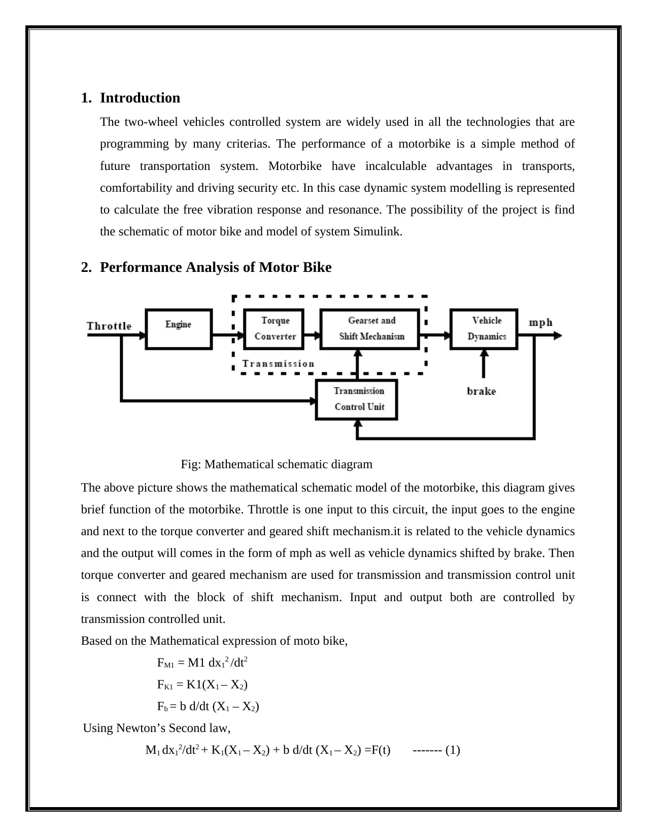
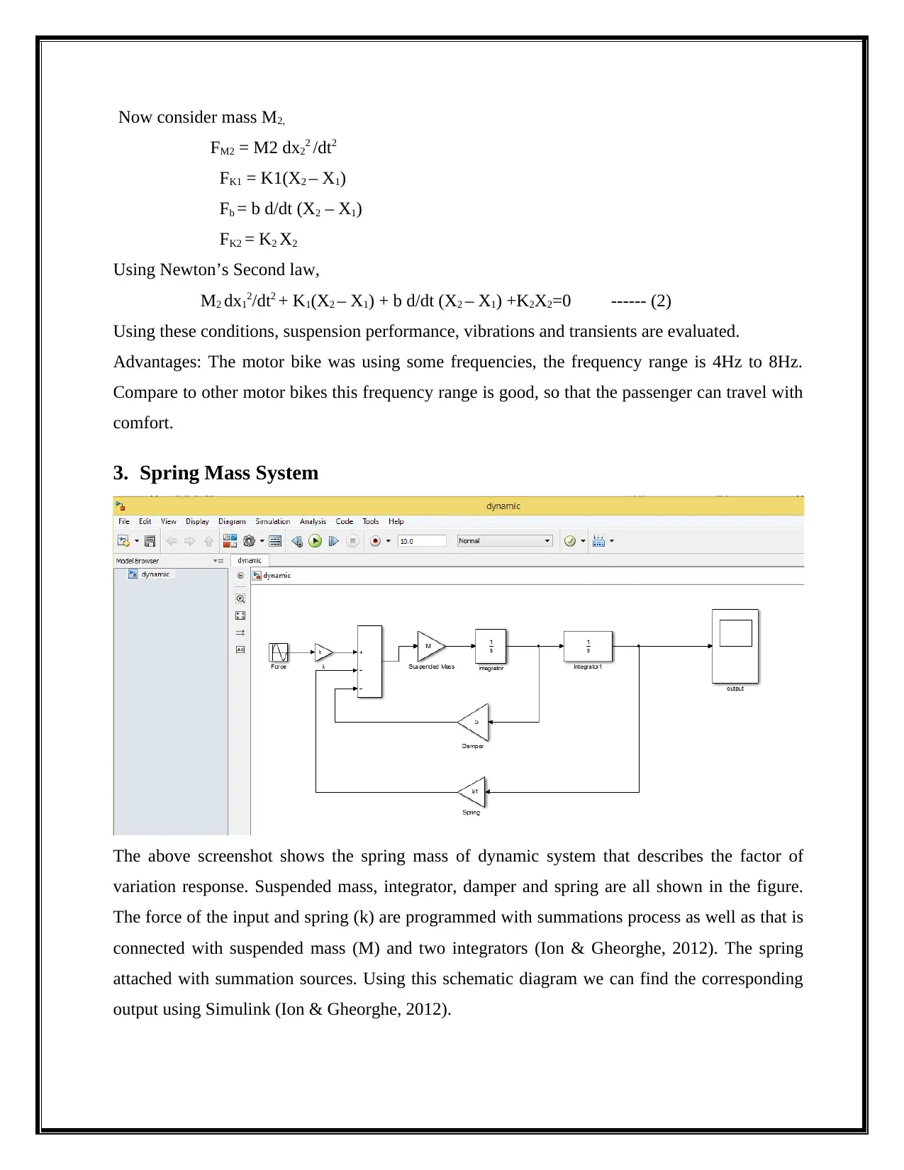
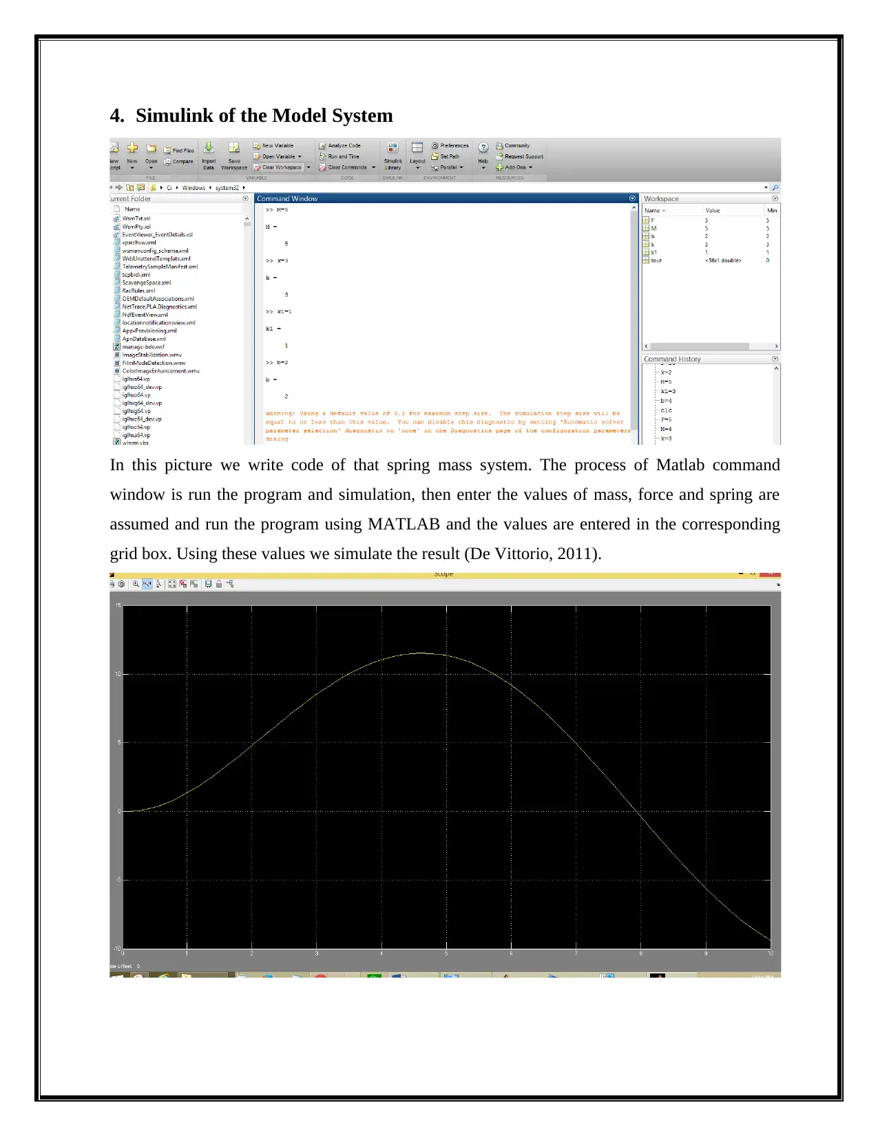
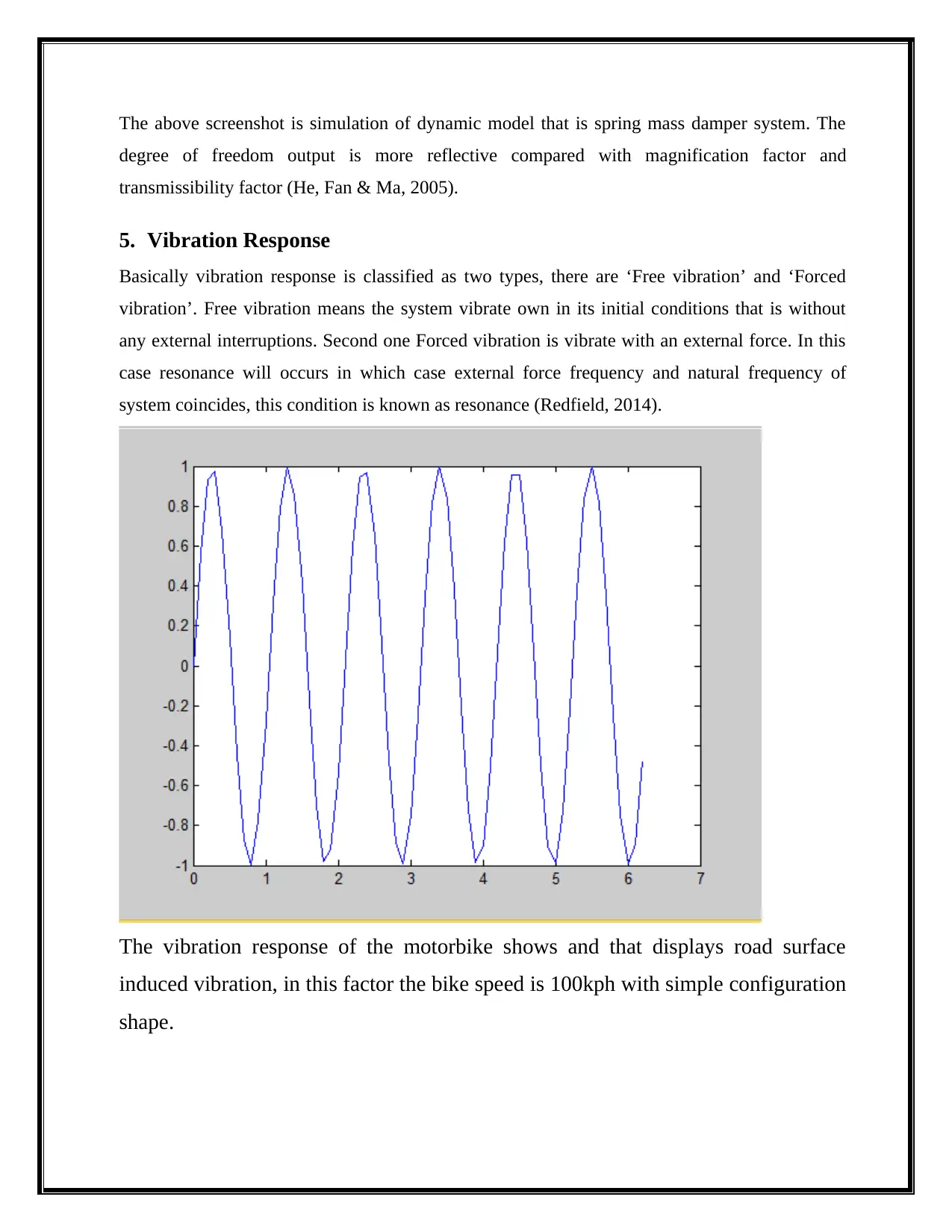
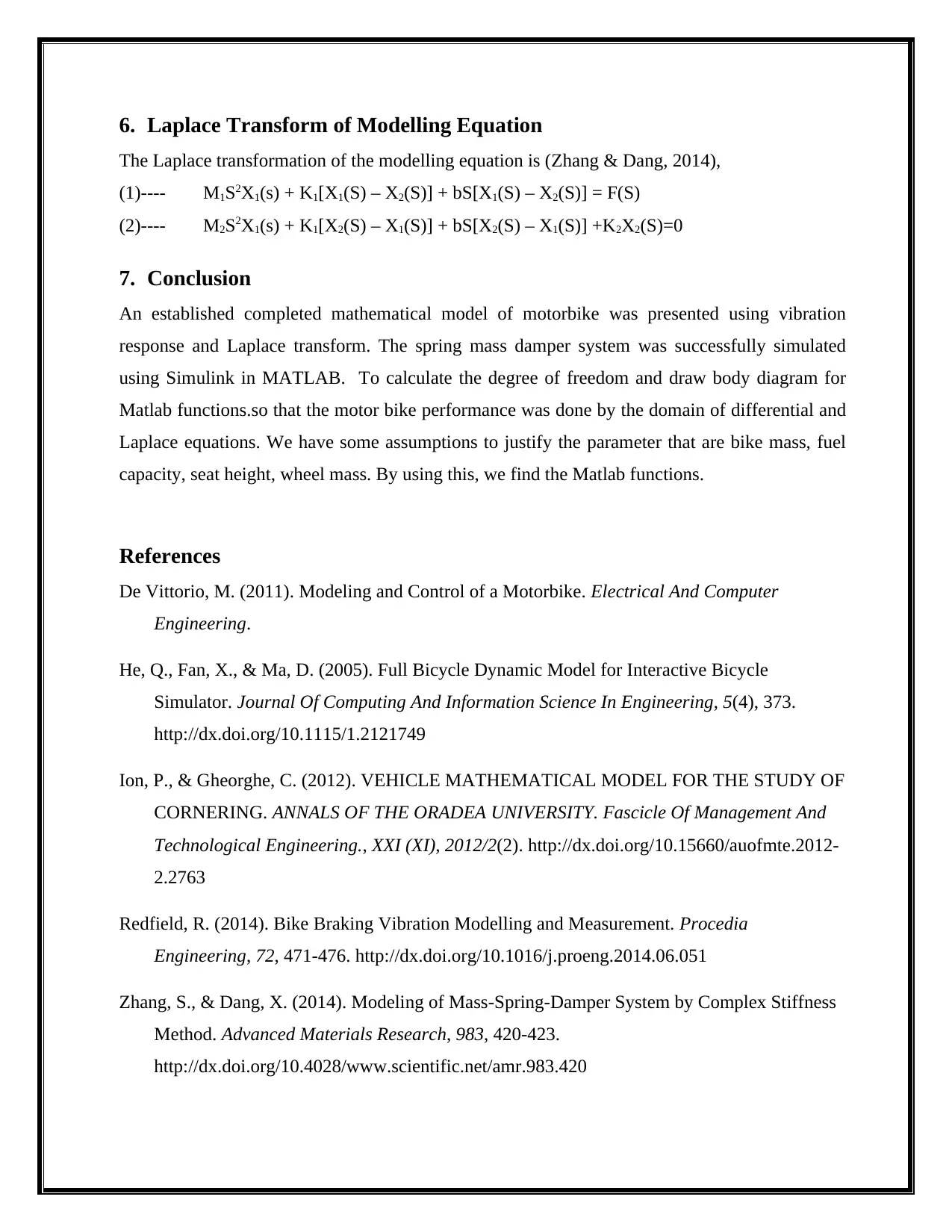
This project focuses on the dynamic system modeling and control of a motorbike. It begins with a mathematical schematic diagram of the motorbike, detailing the relationships between throttle input, engine, torque converter, geared shift mechanism, and vehicle dynamics. The project then formulates the governing equations using Newton's Second Law, considering the masses, springs, and dampers of the system. A spring-mass system model is introduced to describe the vibration response characteristics. The project utilizes Simulink to simulate the dynamic model, demonstrating the behavior of the system under various conditions. The analysis covers both free and forced vibrations, explaining the concept of resonance. The Laplace transform is applied to the modeling equations to further analyze the system's behavior. The project concludes with a discussion of the motorbike's performance, highlighting the influence of factors like bike mass, fuel capacity, and wheel mass on the system's dynamics. References to supporting literature are included.
Document Page
Dynamic System Modelling and Control
tabler-icon-diamond-filled.svg

Paraphrase This Document

Need a fresh take? Get an instant paraphrase of this document with our AI Paraphraser
Document Page
1. Introduction
The two-wheel vehicles controlled system are widely used in all the technologies that are
programming by many criterias. The performance of a motorbike is a simple method of
future transportation system. Motorbike have incalculable advantages in transports,
comfortability and driving security etc. In this case dynamic system modelling is represented
to calculate the free vibration response and resonance. The possibility of the project is find
the schematic of motor bike and model of system Simulink.
2. Performance Analysis of Motor Bike
Fig: Mathematical schematic diagram
The above picture shows the mathematical schematic model of the motorbike, this diagram gives
brief function of the motorbike. Throttle is one input to this circuit, the input goes to the engine
and next to the torque converter and geared shift mechanism.it is related to the vehicle dynamics
and the output will comes in the form of mph as well as vehicle dynamics shifted by brake. Then
torque converter and geared mechanism are used for transmission and transmission control unit
is connect with the block of shift mechanism. Input and output both are controlled by
transmission controlled unit.
Based on the Mathematical expression of moto bike,
FM1 = M1 dx12 /dt2
FK1 = K1(X1 – X2)
Fb = b d/dt (X1 – X2)
Using Newton’s Second law,
M1 dx12/dt2 + K1(X1 – X2) + b d/dt (X1 – X2) =F(t) ------- (1)
Document Page
Now consider mass M2,
FM2 = M2 dx22 /dt2
FK1 = K1(X2 – X1)
Fb = b d/dt (X2 – X1)
FK2 = K2 X2
Using Newton’s Second law,
M2 dx12/dt2 + K1(X2 – X1) + b d/dt (X2 – X1) +K2X2=0 ------ (2)
Using these conditions, suspension performance, vibrations and transients are evaluated.
Advantages: The motor bike was using some frequencies, the frequency range is 4Hz to 8Hz.
Compare to other motor bikes this frequency range is good, so that the passenger can travel with
comfort.
3. Spring Mass System
The above screenshot shows the spring mass of dynamic system that describes the factor of
variation response. Suspended mass, integrator, damper and spring are all shown in the figure.
The force of the input and spring (k) are programmed with summations process as well as that is
connected with suspended mass (M) and two integrators (Ion & Gheorghe, 2012). The spring
attached with summation sources. Using this schematic diagram we can find the corresponding
output using Simulink (Ion & Gheorghe, 2012).
Document Page
4. Simulink of the Model System
In this picture we write code of that spring mass system. The process of Matlab command
window is run the program and simulation, then enter the values of mass, force and spring are
assumed and run the program using MATLAB and the values are entered in the corresponding
grid box. Using these values we simulate the result (De Vittorio, 2011).
tabler-icon-diamond-filled.svg

Paraphrase This Document

Need a fresh take? Get an instant paraphrase of this document with our AI Paraphraser
Document Page
The above screenshot is simulation of dynamic model that is spring mass damper system. The
degree of freedom output is more reflective compared with magnification factor and
transmissibility factor (He, Fan & Ma, 2005).
5. Vibration Response
Basically vibration response is classified as two types, there are ‘Free vibration’ and ‘Forced
vibration’. Free vibration means the system vibrate own in its initial conditions that is without
any external interruptions. Second one Forced vibration is vibrate with an external force. In this
case resonance will occurs in which case external force frequency and natural frequency of
system coincides, this condition is known as resonance (Redfield, 2014).
The vibration response of the motorbike shows and that displays road surface
induced vibration, in this factor the bike speed is 100kph with simple configuration
shape.
Document Page
6. Laplace Transform of Modelling Equation
The Laplace transformation of the modelling equation is (Zhang & Dang, 2014),
(1)---- M1S2X1(s) + K1[X1(S) – X2(S)] + bS[X1(S) – X2(S)] = F(S)
(2)---- M2S2X1(s) + K1[X2(S) – X1(S)] + bS[X2(S) – X1(S)] +K2X2(S)=0
7. Conclusion
An established completed mathematical model of motorbike was presented using vibration
response and Laplace transform. The spring mass damper system was successfully simulated
using Simulink in MATLAB. To calculate the degree of freedom and draw body diagram for
Matlab functions.so that the motor bike performance was done by the domain of differential and
Laplace equations. We have some assumptions to justify the parameter that are bike mass, fuel
capacity, seat height, wheel mass. By using this, we find the Matlab functions.
References
De Vittorio, M. (2011). Modeling and Control of a Motorbike. Electrical And Computer
Engineering.
He, Q., Fan, X., & Ma, D. (2005). Full Bicycle Dynamic Model for Interactive Bicycle
Simulator. Journal Of Computing And Information Science In Engineering, 5(4), 373.
http://dx.doi.org/10.1115/1.2121749
Ion, P., & Gheorghe, C. (2012). VEHICLE MATHEMATICAL MODEL FOR THE STUDY OF
CORNERING. ANNALS OF THE ORADEA UNIVERSITY. Fascicle Of Management And
Technological Engineering., XXI (XI), 2012/2(2). http://dx.doi.org/10.15660/auofmte.2012-
2.2763
Redfield, R. (2014). Bike Braking Vibration Modelling and Measurement. Procedia
Engineering, 72, 471-476. http://dx.doi.org/10.1016/j.proeng.2014.06.051
Zhang, S., & Dang, X. (2014). Modeling of Mass-Spring-Damper System by Complex Stiffness
Method. Advanced Materials Research, 983, 420-423.
http://dx.doi.org/10.4028/www.scientific.net/amr.983.420
Document Page
chevron_up_icon
1 out of 7
circle_padding
hide_on_mobile
zoom_out_icon
[object Object]